Sensors, actuators, and valves are essential components of a car's engine and other systems. They monitor and control various parameters, such as temperature, pressure, flow, position, speed, and timing.
"The difference between a guess and a diagnosis is a multimeter." Every day, thousands of drivers face mysterious engine issues that mechanics charge hundreds to solve. Yet with just one simple tool, you could identify most electrical problems yourself, saving time, money, and frustration.
According to the National Automotive Technicians Association, over 70% of car problems are electrical in nature. Behind your dashboard lies a network of sensors and actuators, the nervous system of your vehicle constantly monitoring and adjusting your engine's performance. When these electrical components fail, they rarely do so dramatically. Instead, they degrade gradually, causing subtle performance issues long before triggering warning lights.
Let me show you how to diagnose these hidden electrical issues using nothing more than a quality multimeter and some basic knowledge.
The Diagnostic Power in Your Hands
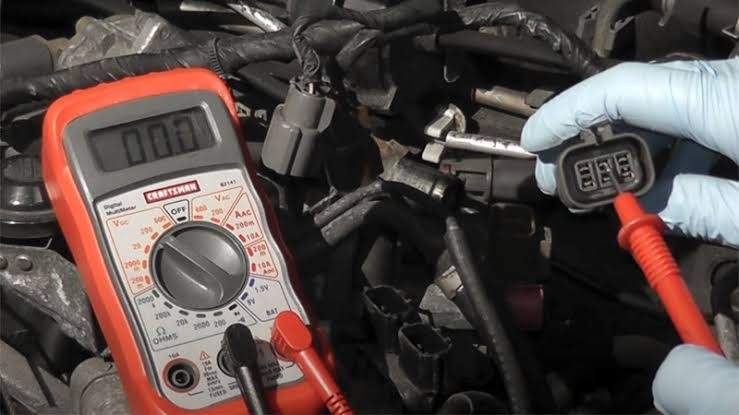
Before we get into specific tests, let's understand the fundamental tool you'll need: a digital multimeter. This device can measure various electrical properties, including:
- Voltage: The electrical pressure in a circuit (measured in volts)
- Resistance: The opposition to current flow (measured in ohms)
- Continuity: The presence of a complete electrical path
A quality automotive multimeter should have these basic functions along with a backlit display for working in dark engine compartments and auto-ranging capability to simplify measurements. You'll want one that can handle at least 20 volts DC for most automotive testing.
Setting Up Your Multimeter Like a Pro
Safety comes first when working with electrical components. Always:
- Turn off the ignition before testing resistance or continuity
- Disconnect the component from its wiring harness when required
- Ensure your multimeter has fresh batteries for accurate readings
- Use insulated probes and avoid touching metal parts while testing
For voltage tests, you'll typically set your multimeter to DC voltage mode (V⎓). For resistance measurements, select the ohms setting (Ω). Most multimeters also have a continuity setting that beeps when a complete circuit is detected, immensely helpful for checking wires and connections.
Testing Common Automotive Sensors
Sensors are your vehicle's sense organs, monitoring everything from air intake to engine temperature. Here's how to test some of the most critical ones:
Mass Air Flow (MAF) Sensor
This crucial component measures incoming air to help your engine computer determine proper fuel delivery.
Pin Configurations:
- 3-Pin MAF: Power (Red/Orange), Ground (Black), Signal (Yellow/Green)
- 5-Pin MAF: Adds IAT Signal (Blue) and IAT Ground (Brown)
Testing Procedure:
- Set multimeter to DC voltage
- Connect black probe to ground pin, red probe to signal pin
- With engine off, you should read 0.5-1.0V
- With engine running, voltage should increase with RPM
If readings remain flat regardless of engine speed, your MAF sensor may be clogged or failing.
Coolant Temperature Sensor (CTS)
This thermistor-type sensor changes resistance as engine temperature varies.
Testing Procedure:
- Disconnect sensor connector
- Set multimeter to resistance (Ω)
- Measure between signal and ground pins
- A cold engine should show high resistance (2000-5000Ω)
- A hot engine should show low resistance (100 - 500Ω)
A sensor that shows unchanging resistance across temperature ranges is faulty and requires replacement.
Oxygen (O2) Sensor
The oxygen sensor measures exhaust oxygen content to help optimize the air-fuel mixture.
Testing Procedure:
- Set multimeter to DC voltage
- Connect black probe to signal ground, red probe to signal wire.
- With engine at operating temperature, voltage should fluctuate between 0.1-0.9V
- A healthy sensor will cycle several times per second
- Alternatively: Set the multimeter to Continuity, it should produce a bip sound when the probes touch each other. Identify 2 wires which are similar in colour "2 whites, 2 blacks" connect each probe to each wire. A bip sound means the heater circuit is okay, if no sound, you might have to replace it.
A "lazy" O2 sensor with slow response times or fixed voltage readings indicates replacement is needed.
Diagnosing Actuators
While sensors gather information, actuators convert electrical signals into mechanical action. Here's how to test common actuators:
Fuel Injectors
Fuel injectors are electromagnetic valves that precisely meter fuel delivery.
Testing Procedure:**
- Set multimeter to resistance (Ω)
- Disconnect injector electrical connector
- Measure between the two pins of the injector
- Most injectors should read between 11 - 16Ω
An open circuit (infinite resistance) or shorted circuit (near-zero resistance) indicates a failed injector.
Variable Valve Timing (VVT) Solenoid
This solenoid controls the timing of your engine's valves for optimal performance.
Testing Procedure:
- Disconnect the solenoid connector
- Set multimeter to resistance (Ω)
- Measure between the power and control terminals
- Most VVT solenoids should read 10 - 50Ω
High resistance readings often indicate internal coil damage requiring replacement.
Valve Testing Techniques
Valves control the flow of fluids and gases throughout your engine. Electrically controlled valves can be tested for proper operation using these methods:
EGR Valve
The Exhaust Gas Recirculation valve reduces emissions by recirculating a portion of exhaust gases.
Testing Procedure:
- Disconnect the valve's electrical connector
- Set multimeter to resistance (Ω)
- For digital EGR valves, measure between control signals and ground
- Typical resistance should be 10 - 50Ω
- For position feedback, set to DC voltage and measure between feedback pin and ground
A properly functioning EGR valve will show voltage changes as the valve position changes.
Purge Valve (EVAP System)
This valve controls the flow of fuel vapor from the charcoal canister to the engine.
Testing Procedure:
- Remove the valve from the vehicle
- Set multimeter to resistance (Ω)
- Measure between the two electrical terminals
- Most purge valves should read 15-30Ω
- For functional testing, apply 12V to the valve, you should hear a distinct click
No audible click combined with resistance outside specifications confirms valve failure.
Interpreting Your Test Results
Understanding what your measurements mean is as important as taking them correctly. Here's a quick guide to common multimeter readings:
- Infinite resistance (OL): Indicates an open circuit, often meaning a broken wire or failed component
- Zero resistance: Suggests a short circuit
- Fluctuating voltage: Normal for many sensors during operation
- Steady voltage when it should fluctuate: Often indicates a sensor failure
- No voltage when power should be present: Suggests a wiring issue or blown fuse
Remember to always compare your readings with the specifications in your vehicle's repair manual. Manufacturer specifications should be your definitive guide as tolerances vary between makes and models.
Real-World Diagnostic Process
Let me walk you through a real-world example of using these testing techniques:
Imagine your check engine light illuminates with code P0118 (Engine Coolant Temperature Circuit High Input). Here's how you'd approach the diagnosis:
- Identify the component: This code relates to the coolant temperature sensor
- Locate the sensor: Usually screwed into the engine block or cylinder head
- Test the wiring: With ignition on, measure voltage at the sensor connector (should be around 5V)
- Test the sensor: Disconnect it and measure resistance across its terminals at different temperatures
- Analyze results: If resistance doesn't change with temperature, replace the sensor
This methodical approach eliminates guesswork and focuses your repair efforts precisely where needed.
Tools for Success
While a multimeter is essential, a few additional tools will enhance your diagnostic capabilities:
- Vehicle-specific repair manual: Provides exact specifications and connector pinouts
- Wire piercing probes: Allow testing without disconnecting connectors
- Terminal release tools: Properly remove terminals without damage
- Electrical contact cleaner: Restore connections affected by corrosion
- Heat gun or lighter: Test temperature-sensitive components
Investing in quality tools pays dividends through accurate diagnoses and successful repairs.
Safety First, Always
Working around your vehicle's electrical system requires careful attention to safety:
- Disconnect the negative battery terminal before working on sensitive electronics
- Never probe airbag circuits, this could trigger deployment
- Use insulated tools when working around the battery or high-current circuits
- Keep flammable materials away from hot engine components
- Wear safety glasses to protect against battery acid or electrical sparks
Your safety equipment is as important as your diagnostic tools.
Conclusion
Testing automotive sensors, actuators, and valves isn't mysterious magic, it's applied science accessible to anyone with the right tools and knowledge. By methodically measuring resistance and voltage, you can identify the root causes of many problems before they escalate into expensive repairs.
Remember that electrical testing is just one piece of the diagnostic puzzle. Mechanical issues, computer programming, and even simple maintenance concerns can mimic electrical problems. Always follow a comprehensive troubleshooting approach that considers all systems.
I've found that electrical diagnosis is one of the most satisfying aspects of automotive repair. There's nothing quite like pinpointing the exact failed component that's been causing headaches for weeks. With practice, patience, and the right approach, you'll develop this valuable skill that saves time and money throughout your vehicle's lifetime.
Comments (0)
Please login to join the discussion
Be the first to comment on this article!
Share your thoughts and start the discussion