Here's a sobering reality check: Over 280 million vehicles worldwide are equipped with OBD systems, yet millions of drivers remain completely clueless about reading their own diagnostic trouble codes when that dreaded check engine light illuminates their dashboard. You don't need to be one of them!
That rhythmic pattern you see when your check engine light starts its morse code FLASH...FLASH...PAUSE...FLASH.FLASH.FLASH isn't random. It's your car literally trying to tell you what's wrong, and I'm about to show you exactly how to decode this automotive language without spending a penny on diagnostic equipment.
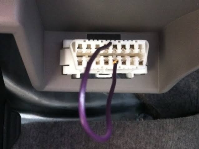
Vehicle's Communication System
Before we get into the hands on techniques, let's establish what we're working with here. Every vehicle manufactured since the 1980s comes equipped with an onboard diagnostics (OBD) system that constantly monitors your engine's performance. When something goes awry, this system stores specific diagnostic trouble codes (DTCs) that pinpoint the exact problem.
The beauty of older vehicles particularly those built before 1996, is that they can communicate these codes directly through your dashboard lights. No expensive scanner required! These pre- OBD-II systems were designed with built-in diagnostic capabilities that allow you to retrieve error codes using nothing more than your ignition key or a simple paperclip.
Method 1: The Classic Key Technique
This method works on most Chrysler, Dodge, Jeep, and many Ford vehicles from the 1990s and early 2000s. I've personally used this technique countless times, and it's saved me hundreds of dollars in diagnostic fees.
Here's the exact procedure:
- Turn your ignition switch ON - OFF - ON - OFF - ON within 5 seconds
- Leave the key in the ON position (don't start the engine)
- Watch your check engine light carefully
- Count the flash patterns that follow
The light will flash in a specific sequence representing numerical codes. Each long pause separates individual codes, while shorter pauses separate digits within the same code. For example, if you see three flashes, pause, then two flashes, that's code 32.
Critical timing note: The entire ON - OFF sequence must be completed within 5 seconds, or the system won't enter diagnostic mode. Practice this rhythm a few times before attempting it with a hot engine.
Method 2: The Odometer Reset Method
This technique is particularly effective on General Motors vehicles, including Chevrolet, GMC, Buick, and Cadillac models from the late 1990s through mid 2000s.
Step by step process:
- Press and hold both the odometer reset button AND the trip reset button simultaneously
- While holding both buttons, turn the ignition to the ON position
- Continue holding the buttons for 3 - 5 seconds after turning the key
- Release both buttons and observe your odometer display
If successful, diagnostic codes will appear directly in your odometer window as alphanumeric characters (like P0300 or P0420). This method is incredibly convenient because it displays codes in the same format that professional scanners use.
Pro tip: Some GM vehicles require you to cycle the ignition ON-OFF-ON while holding the buttons. If the first attempt doesn't work, try the cycling variation.
Method 3: The Paperclip Bridge Technique
For true OBD-I systems (pre 1996 vehicles), this method accesses the most basic level of diagnostic communication. It's particularly common on Honda, Acura, Toyota, and Lexus vehicles from the 1980s and early 1990s.

What you'll need:
- One standard paperclip or 16-gauge jumper wire
- Basic knowledge of your vehicle's diagnostic connector location
The procedure:
- Locate your diagnostic connector (usually under the dashboard on the driver's side)
- With the ignition OFF, insert the paperclip into the designated terminals
- Honda/Acura: Bridge the two terminals in the blue diagnostic connector
- Toyota/Lexus: Bridge terminals TE1 and E1 in the diagnostic box
- GM: Bridge terminals A and B in the ALDL connector
- Turn the ignition to the ON position (engine off)
- Observe the check engine light flash pattern
Decoding the flashes:
- Long flash = 10
- Short flash = 1
- Extended pause = separation between codes
For instance: Long flash, short flash, short flash, PAUSE, short flash, short flash, short flash = Code 12, Code 3.
Method 4: Advanced Dashboard Diagnostic Mode
Some vehicles, particularly certain Nissan, Infiniti, and Subaru models, have hidden diagnostic modes accessible through specific pedal and switch combinations.
Nissan/Infiniti procedure:
- Ensure the accelerator pedal is fully released
- Turn ignition ON and wait exactly 3 seconds
- Quickly press and release the accelerator pedal 5 times within 5 seconds
- Wait 7 seconds, then press and hold the accelerator for 10 seconds
- Release the pedal and count the check engine light flashes
Subaru variation:
- Turn ignition OFF
- Press and hold the trip reset button
- Turn ignition ON while continuing to hold the trip button
- Release the trip button when the display begins flashing
Method 5: The Multimeter Flash Reading Technique
For the technically inclined, this method provides the most precise flash pattern reading on older vehicles. You'll need a basic digital multimeter with DC voltage capability.
Setup procedure:
- Connect the multimeter's positive lead to the check engine light circuit
- Connect the negative lead to a good ground
- Set the multimeter to DC voltage, 20V range
- Follow the appropriate key sequence for your vehicle
- Watch the voltage readings instead of the light flashes
This method eliminates the guesswork of counting rapid flashes and provides a clear voltage pattern you can record for accurate code interpretation.
What Those Codes Actually Mean
Once you've successfully retrieved your codes, the real work begins. Here's how to interpret the most common patterns:
Two digit codes (OBD-I systems):
- Code 12: Normal system operation (not a fault)
- Code 13: Oxygen sensor circuit
- Code 21: Throttle position sensor
- Code 34: MAP sensor low
- Code 55: End of diagnostic sequence
More codes
- 1 Normal Condition.
- 2 Air Flow Meter signal.
- 3 Ignition signal.
- 4 Engine Coolant Temperature Sensor signal.
- 5 Oxygen Sensor.
- 6 RPM signal (Crank Angle Pulse).
- 7 Throttle Position Sensor signal.
- 8 Intake Air Temperature Sensor signal.
- 9 Vehicle Speed Sensor signal.
- 10 Starter signal. (STA signal)
- 11 Switch signal.
- 11 ECU/ECM.
- 12 Knock Control Sensor signal.
- 12 RPM signal.
- 13 Knock Control CPU (ECM).
- 13 RPM signal.
- 14 Turbocharger Pressure.
- 14 Ignition signal.
- 21 Oxygen Sensor.
- 22 Engine Coolant Temperature Sensor signal.
- 23 Intake Air Temperature Sensor signal.
- 24 Intake Air Temperature Sensor signal.
- 25 Air-Fuel Ratio Lean.
- 26 Air-Fuel Ratio Rich.
- 27 Sub Oxygen Sensor signal.
- 28 No. 2 Oxygen Sensor signal.
- 31 Air Flow Meter signal (Vacuum Sensor signal).
- 32 Air Flow Meter signal.
- 34 Turbocharger Pressure signal.
- 35 Turbocharger Pressure Sensor signal.
- 35 HAC Sensor signal.
- 41 Throttle Position Sensor signal.
- 42 Vehicle Speed Sensor signal.
- 43 Starter signal.
- 51 Switch signal.
- 52 Knock Sensor signal.
- 53 Knock Sensor signal.
- 54 Inter cooler ECM signal.
- 71 EGR System.
- 72 Fuel Cut Solenoid signal.
- 78 Fuel Pump Control signal.
- 81 TCM Communication.
- 83 TCM Communication.
- 84 TCM Communication.
- 85 TCM Communication.
Three digit codes (transitional systems):
These often correspond to P-codes in later OBD-II systems
Consult manufacturer-specific diagnostic charts for interpretation
Modern alphanumeric codes:
P0xxx: Powertrain codes (engine, transmission)
- P0101 – Mass air flow (maf) sensor performance
- P0171 – System too lean (bank 1)
- P0300 – Random/multiple cylinder misfire detected
- P0420 – Catalytic converter efficiency below threshold
- P0442 – Evaporative emission system leak (small)
- P0113 – Intake air temperature sensor circuit high
- P0700 – Transmission control system malfunction
B0xxx: Body codes (airbags, lighting)
- B0020 – Driver frontal deployment loop resistance
- B0092 – Passenger airbag deactivation indicator
- B1342 – ECU fault detected
- B1231 – Crash sensor communication fault
- B1201 – Fuel sender open circuit
- B1600 – Key transponder fault
- B2575 – Headlamp control circuit high
C0xxx: Chassis codes (ABS, steering)
- C0035 – Left front wheel speed sensor
- C0040 – Right front wheel speed sensor
- C0241 – ABS pump motor circuit malfunction
- C0110 – ABS pump motor malfunction
- C1234 – Yaw rate sensor fault
- C1288 – Steering sensor fault
- C0561 – System disabled information stored
U0xxx: Network communication codes
- U0100 – Lost communication with ecm/pcm
- U0121 – Lost communication with abs module
- U0140 – Lost communication with body control module
- U0073 – Control module communication bus off
- U0155 – Lost communication with instrument panel cluster
- U0422 – Invalid data from body control module
- U0415 – Invalid data from abs module
Critical Safety Considerations
Never attempt these procedures while driving! Always perform diagnostic code retrieval with the vehicle safely parked and the parking brake engaged. Additionally, remember that clearing codes doesn't fix the underlying problem, it only erases the computer's fault memory.
If you retrieve a code indicating engine misfire (like P0300 series), catalyst damage, or oxygen sensor failure, address these issues promptly. Continuing to drive with these faults can cause expensive secondary damage to your catalytic converter or engine components.
When Professional Diagnosis Is Essential
While these manual methods are incredibly useful for basic troubleshooting, they have limitations. Modern vehicles with complex emissions systems, hybrid powertrains, or multiple computer modules often require professional grade diagnostic equipment for comprehensive analysis.
If your manual code retrieval attempts yield no results, or if you're dealing with intermittent problems that don't trigger consistent codes, it's time to consult a qualified technician with advanced diagnostic capabilities.
References and Further Reading
The information in this article is compiled from factory service manuals, automotive technical bulletins, and decades of hands-on diagnostic experience. For manufacturer-specific procedures, always consult your vehicle's service manual or authorized repair information sources Society of Automotive Engineers and National Institute for Automotive Service Excellence.
Remember: your vehicle's diagnostic system is sophisticated engineering designed to help you maintain optimal performance and emissions compliance. By learning to communicate with this system directly, you're taking control of your automotive maintenance destiny, one flash pattern at a time.
That blinking light isn't just an annoyance, it's your car's way of keeping you informed, safe, and mobile. Master these techniques, and you'll never be left guessing what your engine is trying to tell you again.
Comments (0)
Please login to join the discussion
Be the first to comment on this article!
Share your thoughts and start the discussion