Interactive Explorer
4 Pin Relay Function and Testing
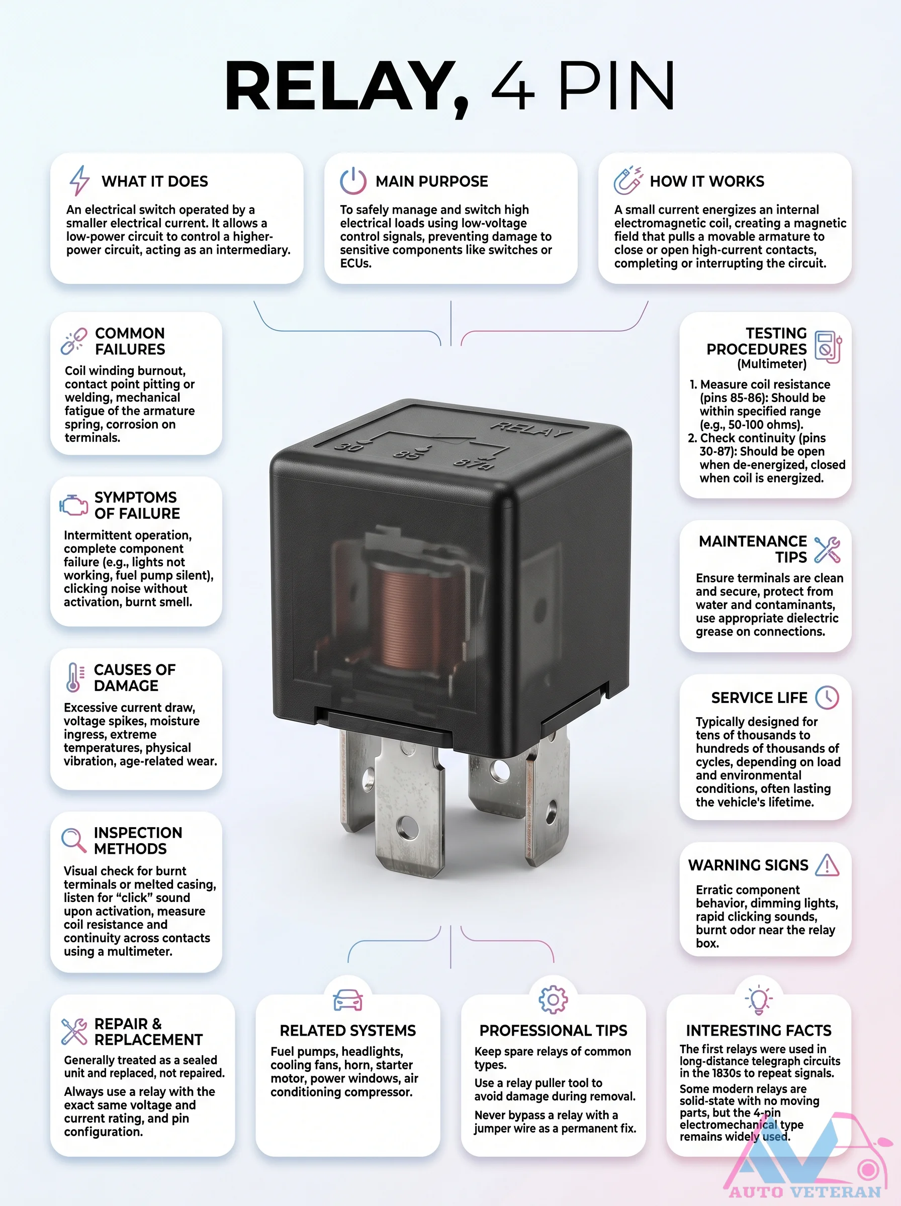
A 4 pin relay is an electromagnetic switch that uses a low current to control a high current circuit, protecting sensitive components like the ECU. It works by energizing a coil to create a magnetic field that pulls an armature to connect the high current contacts. Common failures include coil burnout, contact welding, and mechanical fatigue. Testing involves measuring coil resistance between pins 85 and 86 (typically 50-100 ohms) and checking continuity between pins 30 and 87 which should be open when de energized and closed when energized. Systems like fuel pumps, headlights, cooling fans, horn, and starter motors rely on this component. Symptoms of failure include intermittent operation, complete component failure, clicking without activation, or a burning smell. Causes include excessive current draw, voltage spikes, moisture, extreme temperatures, and vibration. Regular inspection and dielectric grease on connections can extend service life which often lasts the vehicle's lifetime.
4-Pin Relay Internal Working Mechanism and Applications
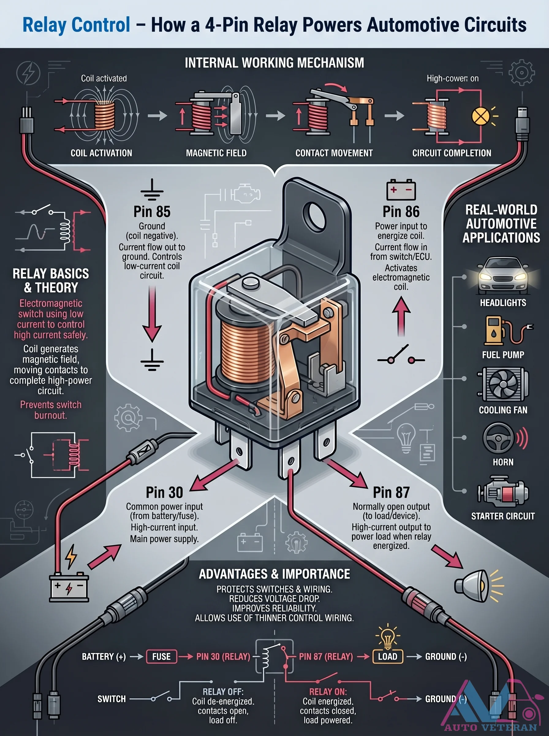
Understanding the internal working mechanism of a 4-pin automotive relay reveals how electromagnetic coil activation creates a magnetic field that moves contacts to complete high-power circuits. This process allows low-current control signals from switches or ECUs to safely operate high-power components like headlights, fuel pumps, cooling fans, and horns while protecting switches from burnout and reducing voltage drop in wiring systems.
4-Pin Relay Wiring Diagram and Testing
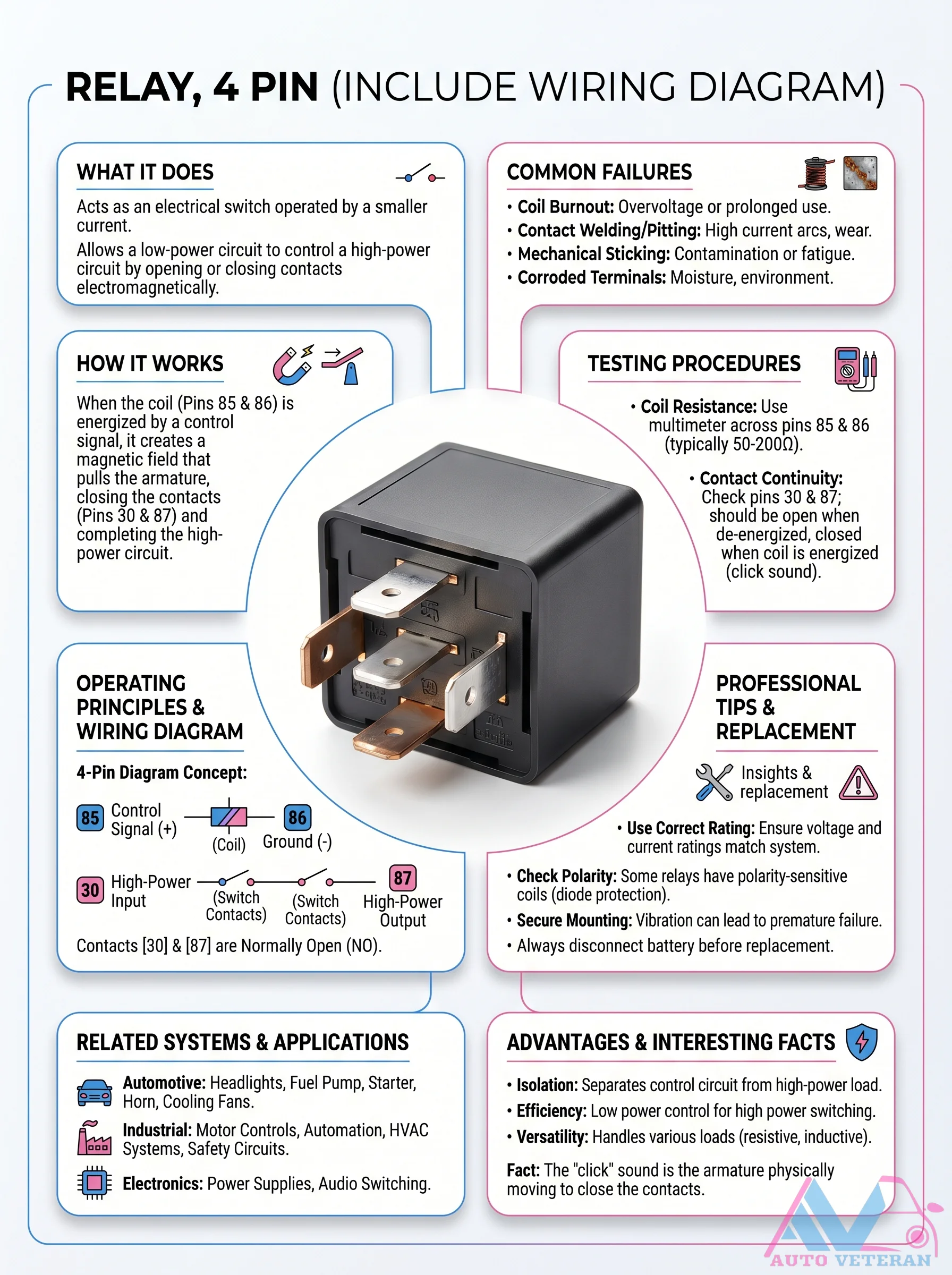
This 4-pin relay acts as an electrical switch, allowing a low-power control circuit to operate a high-power load such as headlights or a fuel pump. The coil (pins 85 and 86) draws a small current to create a magnetic field that pulls the armature, closing the normally open contacts (pins 30 and 87) to complete the high-power circuit. Common failures include coil burnout from overvoltage, contact welding from high current arcs, mechanical sticking due to contamination, and corroded terminals from moisture. To test, measure coil resistance across pins 85 and 86 (typically 50 to 200 ohms) and check contact continuity: pins 30 and 87 should be open when the coil is de-energized and closed when energized (you should hear a click). Always use the correct voltage and current rating, ensure proper mounting to avoid vibration failure, and disconnect the battery before replacement.
4-Pin Relay Working Principle and Pin Layout Explained
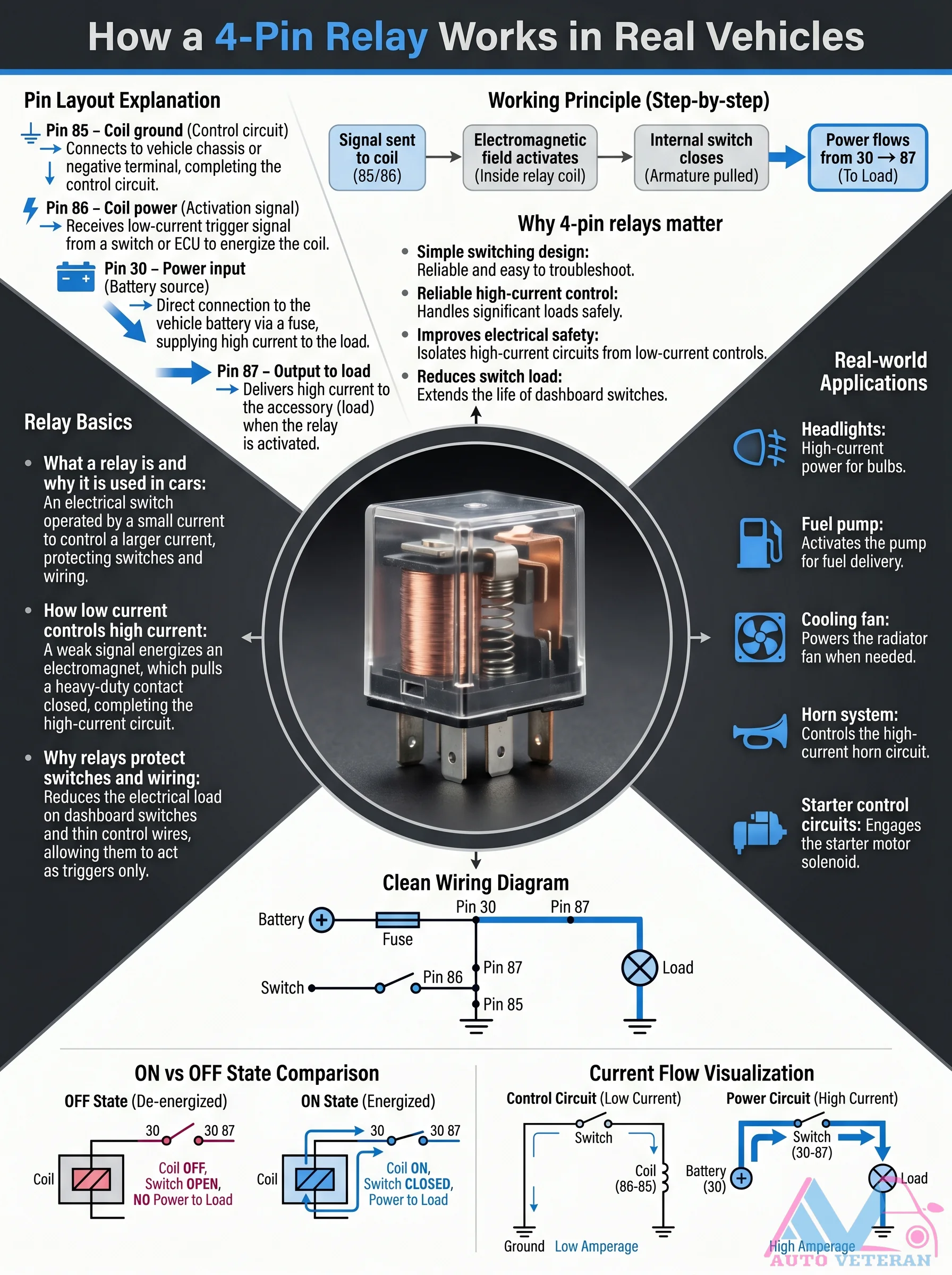
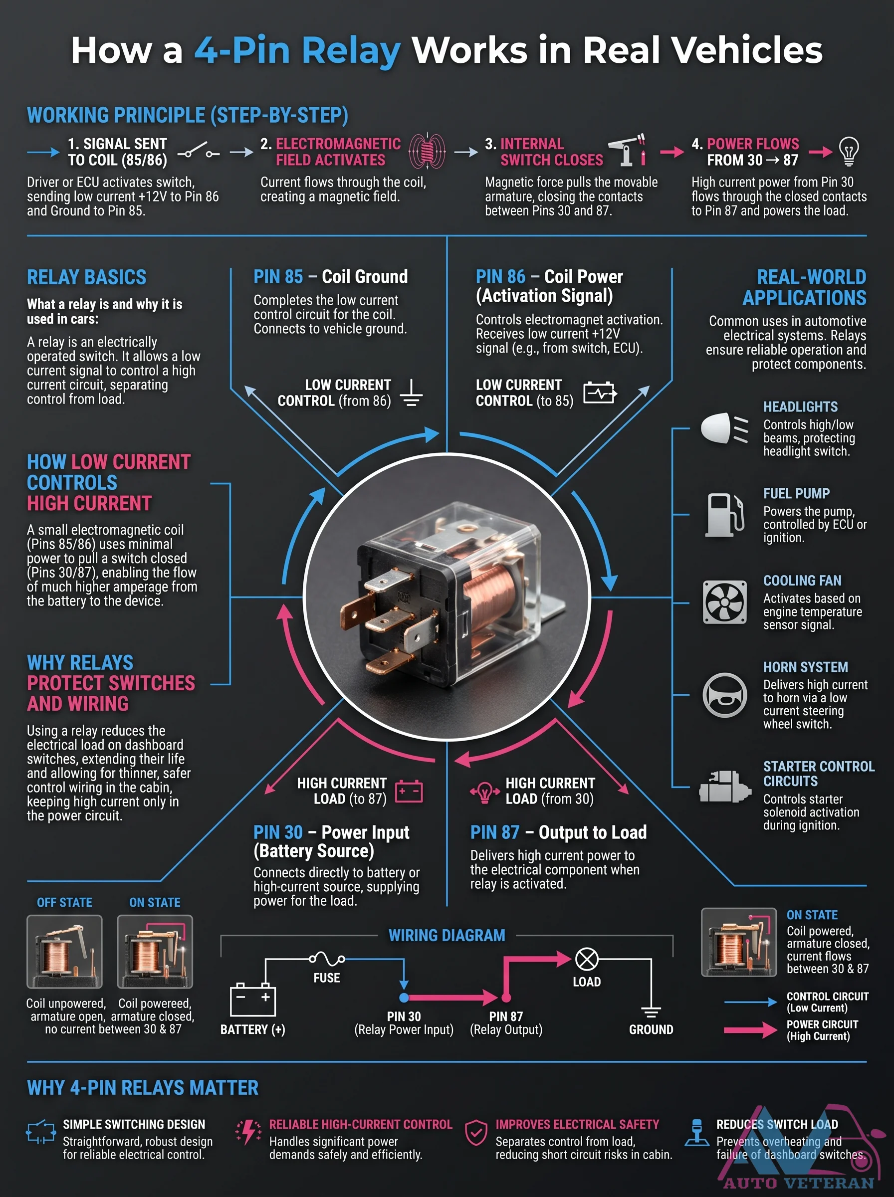
Understanding how a 4-pin relay functions in automotive applications begins with its pin configuration: Pin 85 serves as the coil ground, connecting to the vehicle chassis; Pin 86 receives the low-current trigger signal from a switch or ECU; Pin 30 provides the high-current power input directly from the battery; and Pin 87 delivers that power to the load when activated. The working principle involves a small control current energizing an electromagnetic coil, which then closes a heavy-duty contact to complete the high-current circuit. This design isolates high-current circuits from low-current controls, protecting dashboard switches and wiring while reliably handling significant loads like headlights, fuel pumps, cooling fans, horn systems, and starter control circuits.
4-Pin Relay Working Principle Step by Step
Understanding how a 4-pin relay functions in automotive applications begins with the low current control signal sent from the driver or ECU to pin 86, which then flows through the electromagnetic coil to ground at pin 85. This creates a magnetic field that activates the internal switch, closing the contacts between pins 30 and 87 to allow high current power from the battery to flow to the load, such as headlights, fuel pumps, or cooling fans. This separation of low current control circuits from high current load circuits protects dashboard switches, reduces wiring hazards, and ensures reliable operation of critical vehicle systems.
4-Stroke Cycle Piston Basics and Common Problems
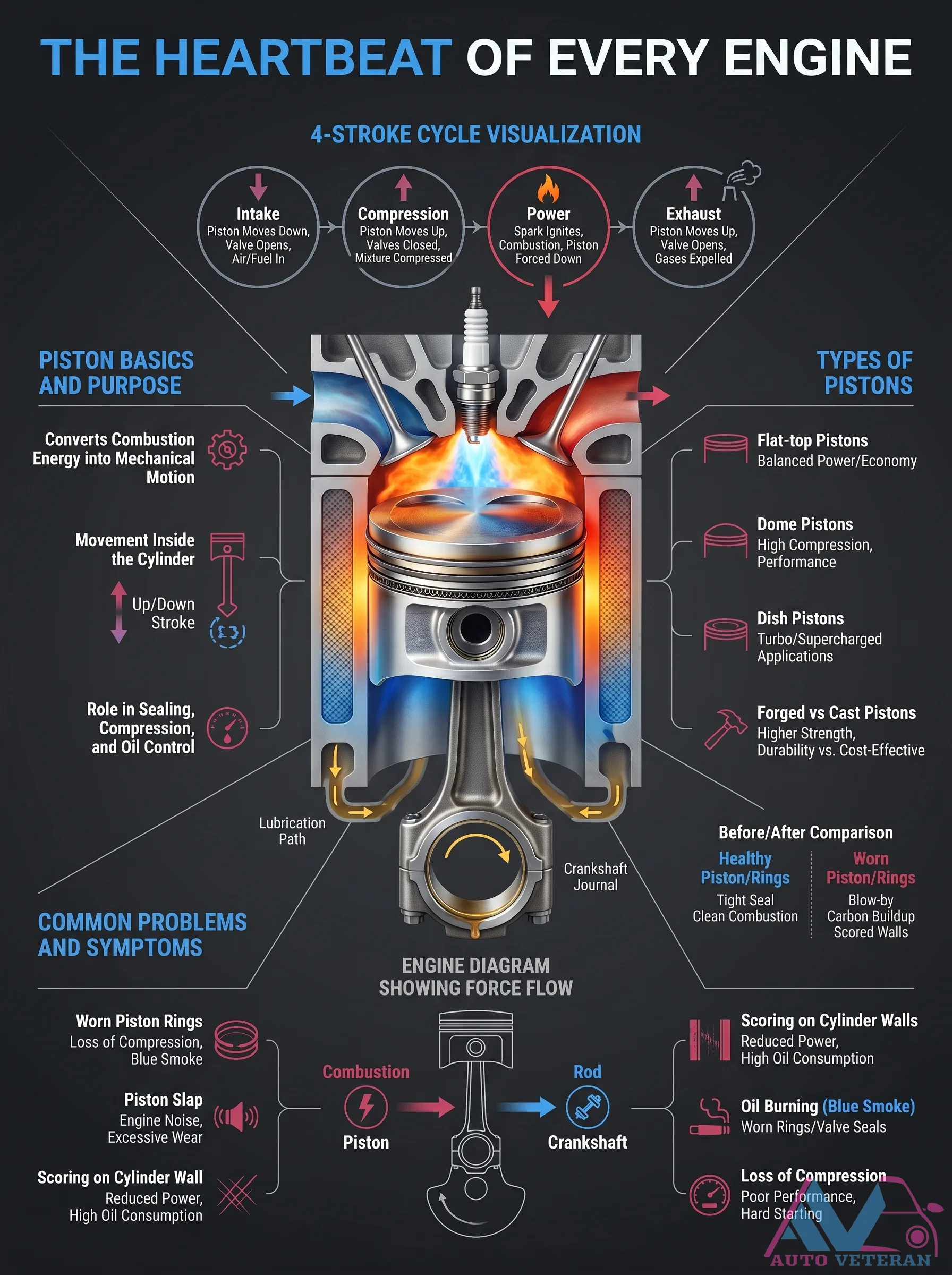
The four-stroke cycle of intake, compression, power, and exhaust drives piston movement, converting combustion into mechanical motion. Piston types like flat-top, dome, and dish serve specific purposes in balancing power, economy, or high-performance applications. Common issues include worn rings causing blow-by, scored cylinder walls, loss of compression, reduced power, blue smoke from oil burning, and piston slap noise, all leading to poor engine performance and high oil consumption.
4-Stroke Engine Cycle Phases Explained
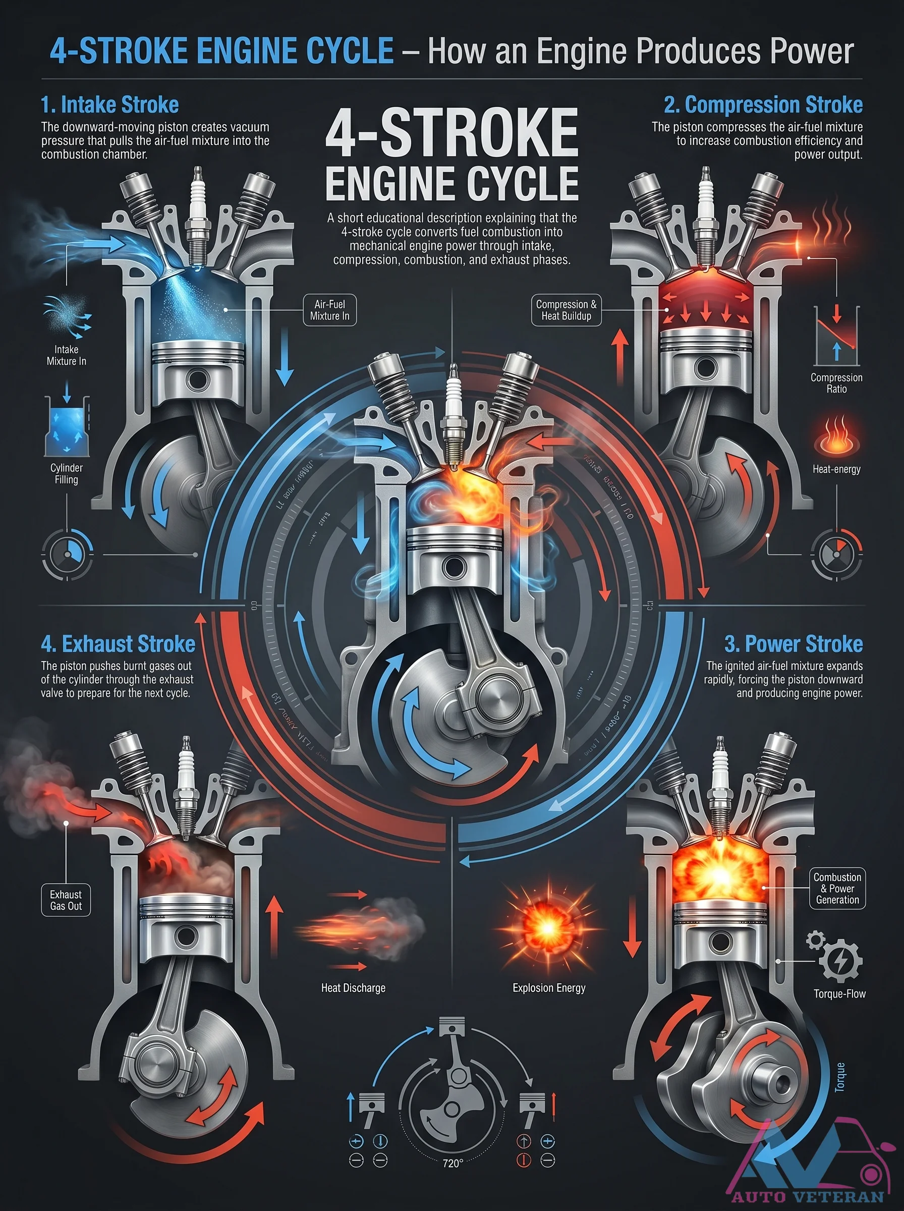
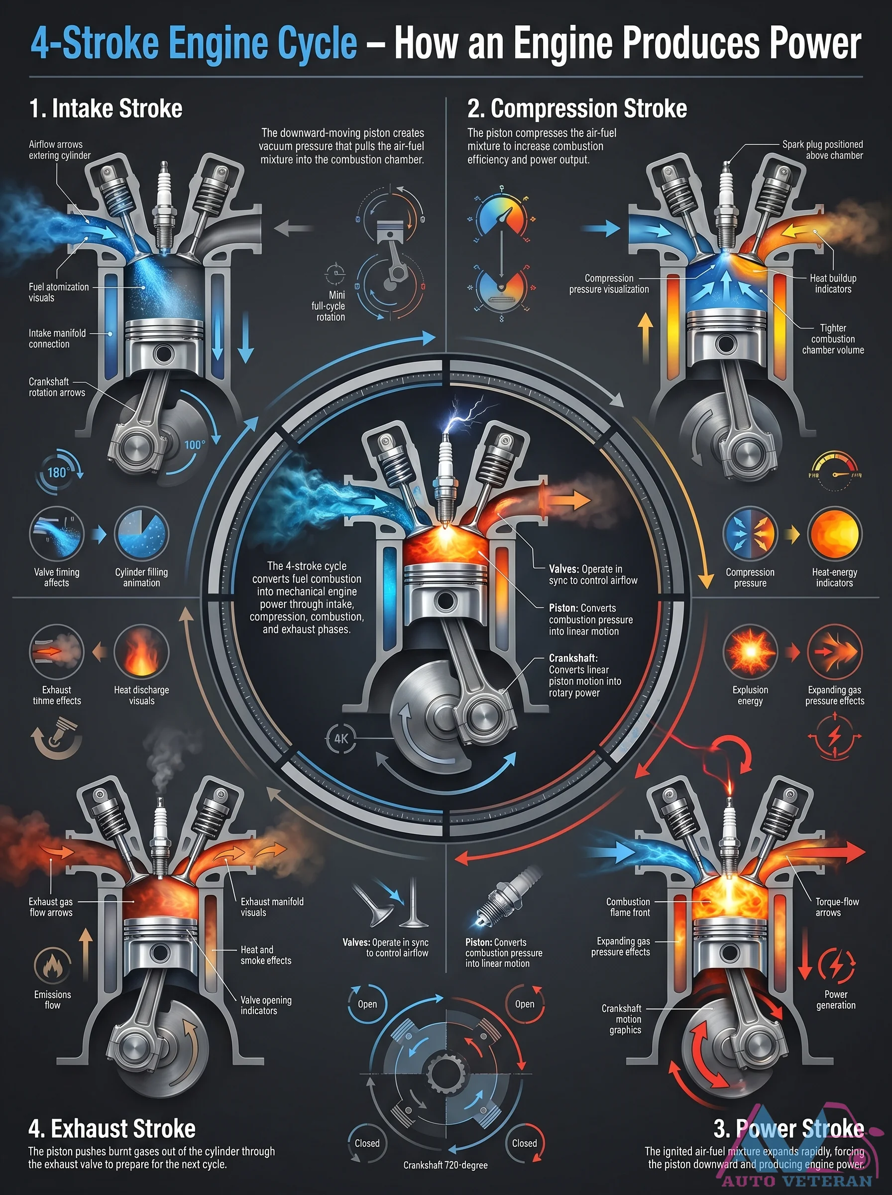
The four stroke engine cycle is a precise sequence of intake compression power and exhaust strokes that transforms fuel combustion into mechanical rotation. During the intake stroke the piston moves downward creating vacuum that draws in the air fuel mixture. The compression stroke then squeezes this mixture to increase combustion efficiency. The power stroke ignites the compressed mixture causing rapid expansion that forces the piston downward generating torque. Finally the exhaust stroke pushes out burned gases through the open exhaust valve completing the cycle. This continuous loop of suction squeeze bang and blow is the fundamental process behind nearly every internal combustion engine on the road.
4-Stroke Engine Cycle Step-by-Step
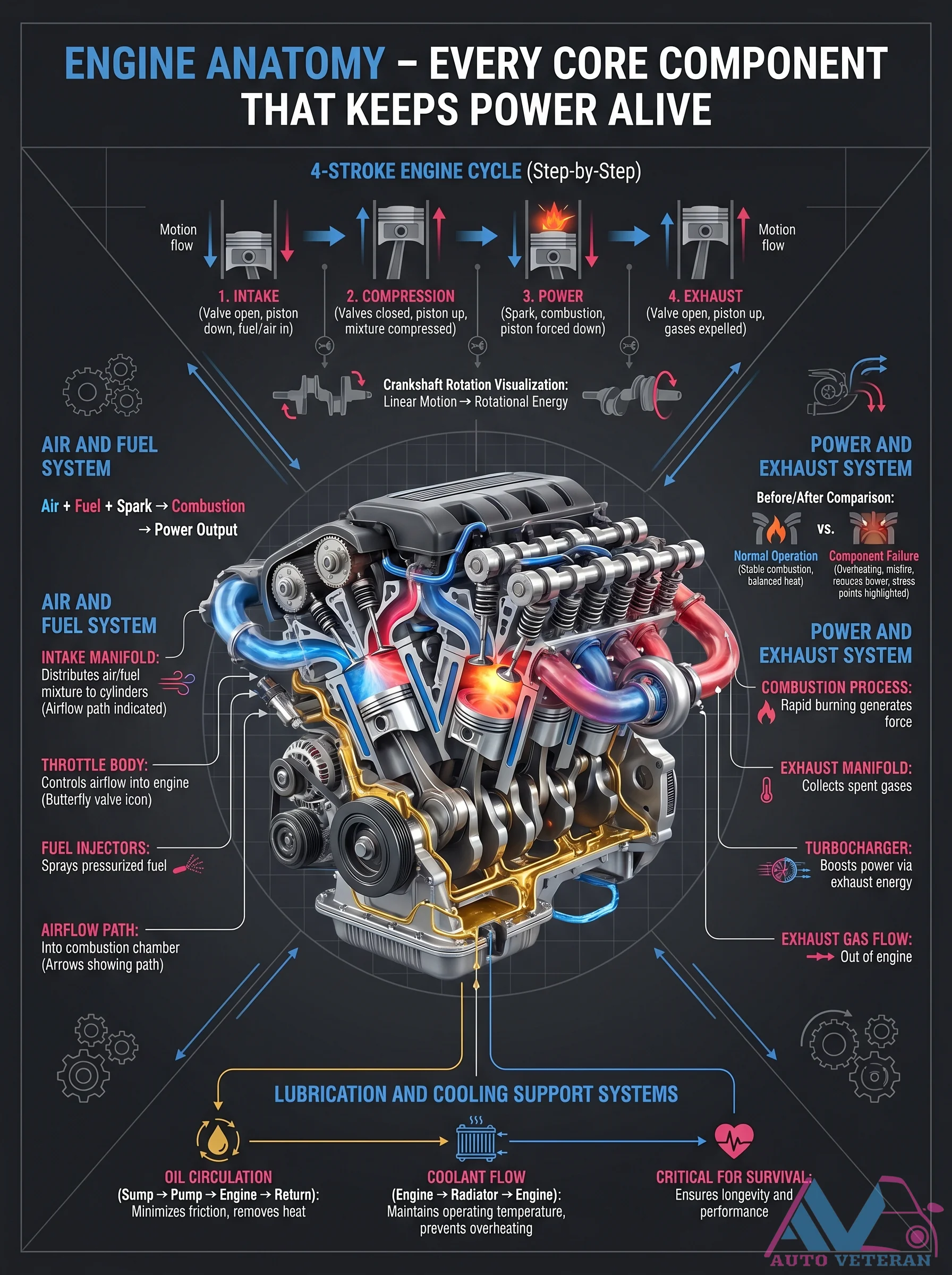
This detailed diagram breaks down the core anatomy of an internal combustion engine, covering the four stroke cycle: intake, compression, power, and exhaust. It illustrates air and fuel path through the intake manifold, throttle body, and fuel injectors, combustion process, exhaust flow through manifold and turbocharger, plus cooling and lubrication systems. It also shows a before and after comparison of normal operation versus component failure, highlighting how fuel, spark, and combustion translate into rotational energy.
4-Stroke Engine Cycle Steps
The four stroke cycle powers your engine through Intake, Compression, Power, and Exhaust strokes, each precisely timed by camshaft operated valves. During intake, the piston creates vacuum to draw in air fuel mixture; compression raises temperature and pressure for efficient combustion. The power stroke ignites the mixture, forcing the piston downward, turning the crankshaft. Finally, exhaust expels burnt gases. This sequence converts linear piston motion into rotational force, delivering torque and horsepower.
40A SPDT Relay Failure Symptoms & Inspection
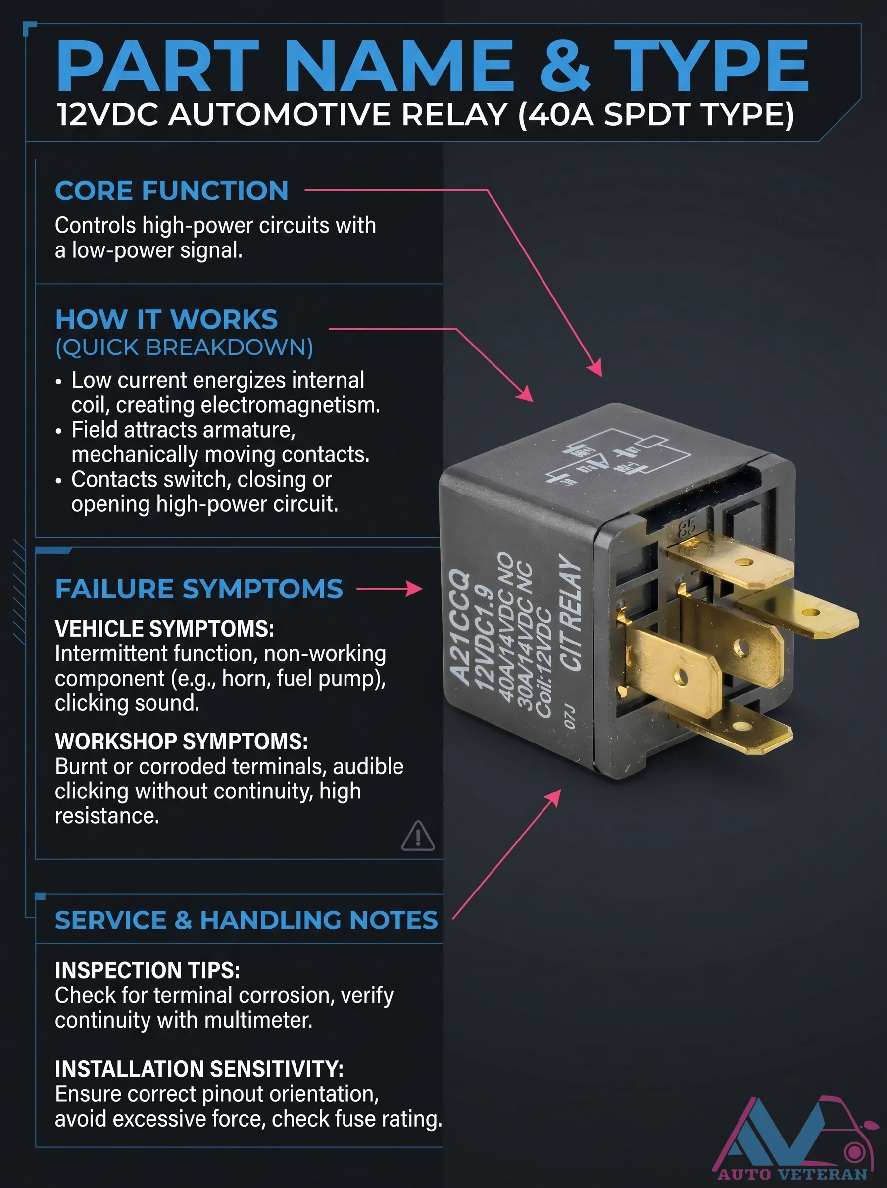
This 12VDC automotive relay, a 40A SPDT type, is the unsung hero of your vehicle's electrical system. It lets a low power signal control high current circuits like fuel pumps, cooling fans, and headlights. When it fails, you may hear an audible clicking but the circuit won't work, due to burnt or corroded terminals, high resistance, or internal arcing. Always check for terminal corrosion, verify continuity with a multimeter, and ensure correct pinout orientation during replacement to avoid frying your fuse.
4WD System Diagram with Mode Selector and Locking Hubs
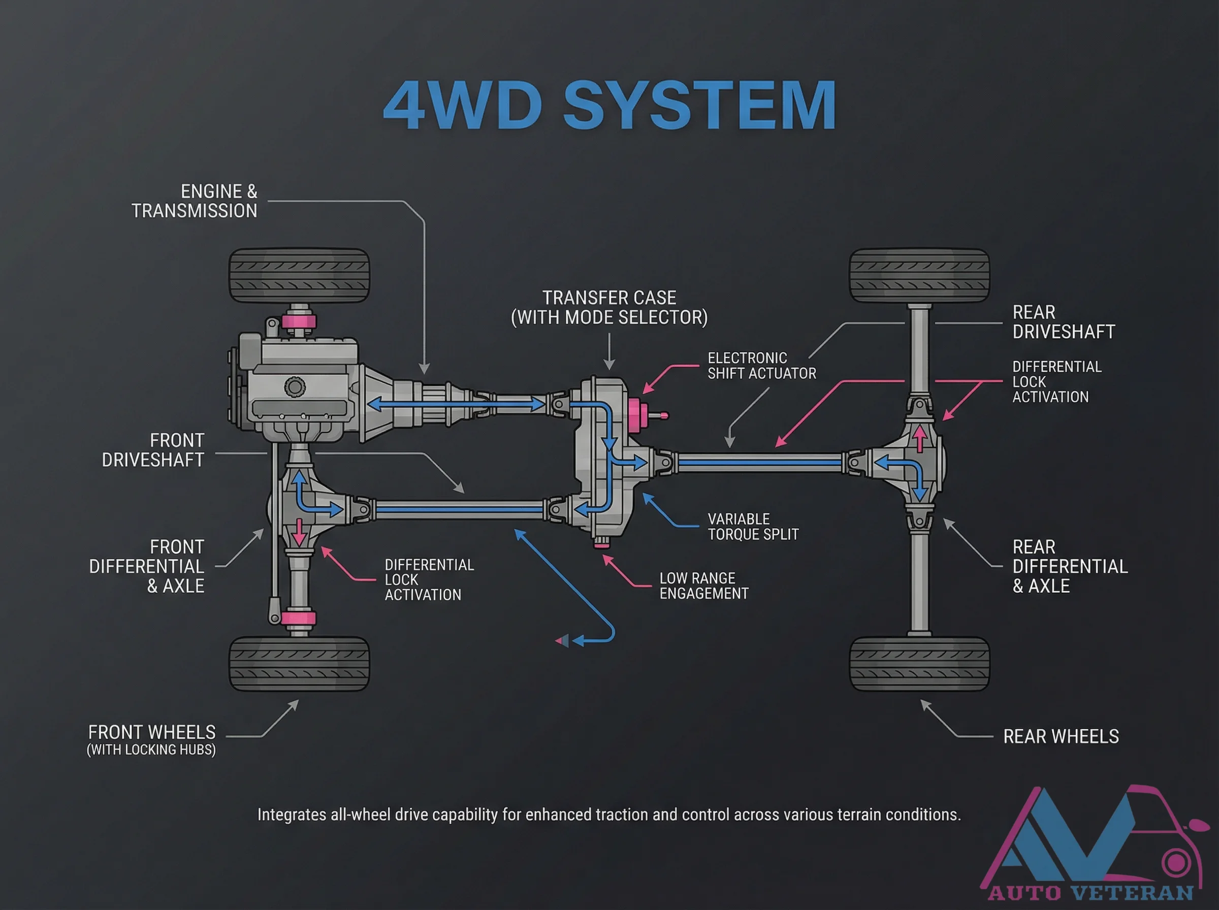
This detailed schematic illustrates the complete architecture of a 4WD system featuring a mode selector, electronic shift actuator, and locking hubs. Key components include the engine and transmission, transfer case, front and rear driveshafts, differentials with axle lock activation, and a variable torque split mechanism. The system integrates all wheel drive capability to provide enhanced traction and control across diverse terrain conditions, with specific engagement for low range and differential lock functions.
4WD System Power Flow Distribution Diagram
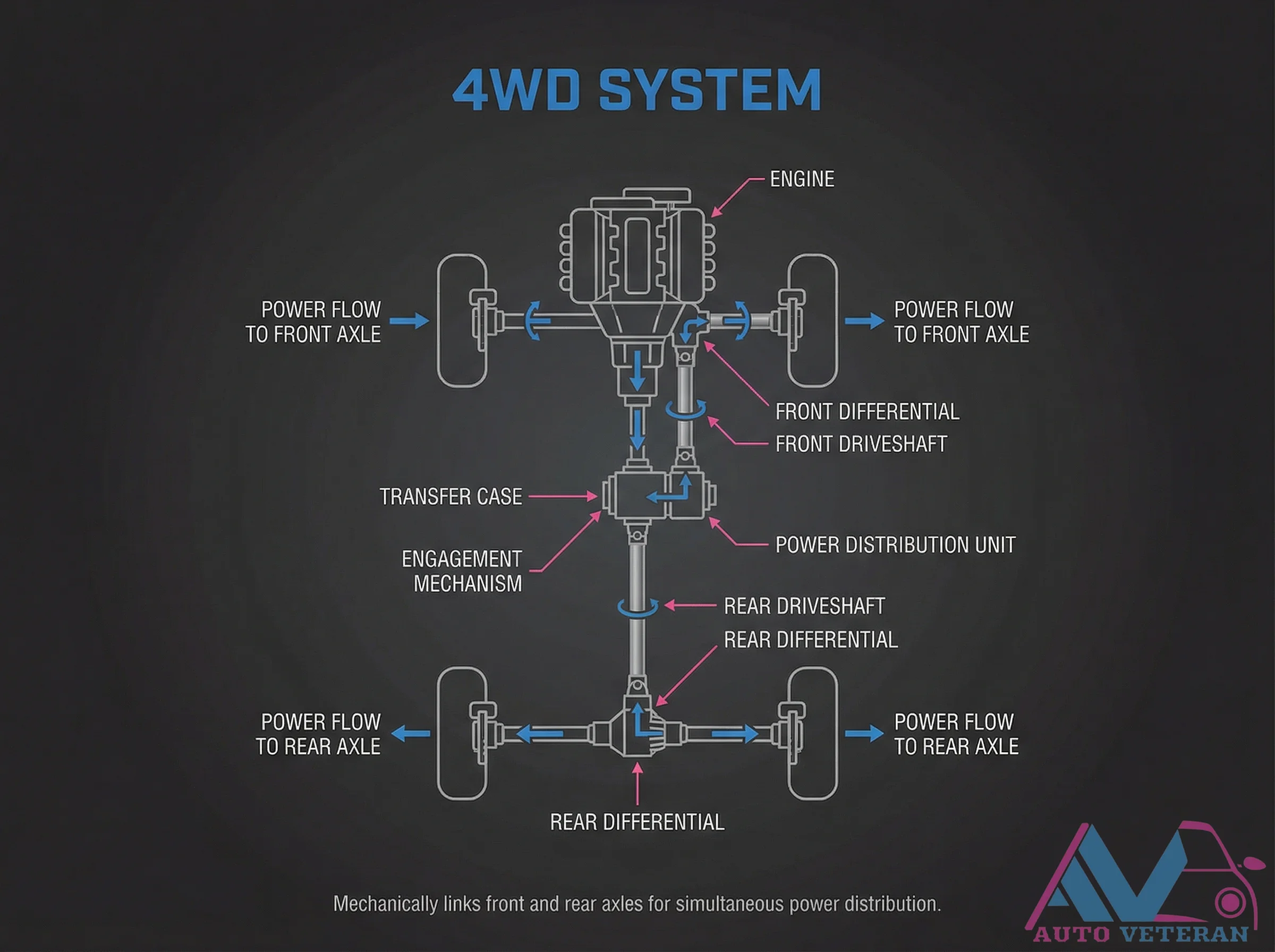
This detailed diagram illustrates the complete power flow path in a 4WD system, showing how engine power is distributed through the transfer case and power distribution unit to both front and rear axles simultaneously. The visual representation clearly depicts the mechanical linkage between front and rear differentials via driveshafts, with specific emphasis on the engagement mechanism that enables synchronized power delivery to all wheels for optimal traction in various driving conditions.