Interactive Explorer
Dashboard Warning Lights and Their Common Causes
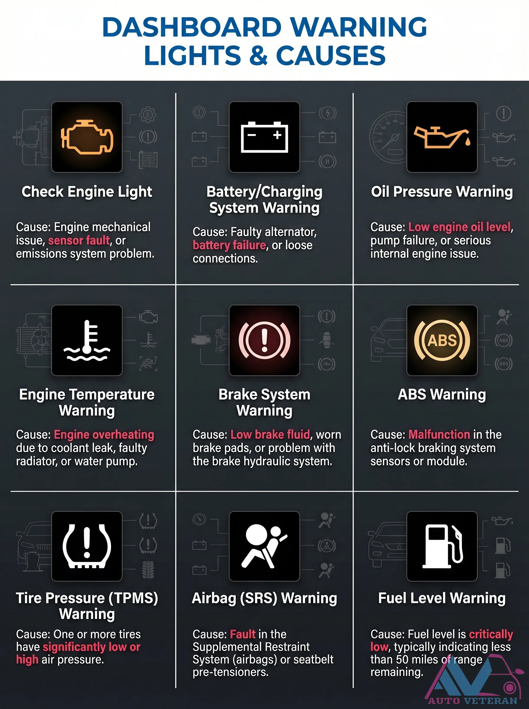
Understanding what triggers your vehicle's dashboard warning lights is crucial for safe operation. The Check Engine Light often indicates engine mechanical issues, sensor faults, or emissions problems. A Battery/Charging Warning typically points to a faulty alternator, battery failure, or loose connections. The Oil Pressure Warning signals low engine oil levels, pump failure, or serious internal engine issues. Engine Temperature Warnings alert you to overheating from coolant leaks, faulty radiators, or water pump failures. Brake System Warnings can mean low brake fluid, worn pads, or hydraulic system problems. ABS Warnings indicate malfunctions in the anti-lock braking system's sensors or module. Tire Pressure (TPMS) Warnings show significantly low or high air pressure in one or more tires. Airbag (SRS) Warnings reveal faults in the Supplemental Restraint System or seatbelt pre-tensioners. Fuel Level Warnings signal critically low fuel, usually with less than 50 miles of range remaining. Recognizing these causes helps you address issues promptly and maintain vehicle safety.
Dashboard Warning Lights Causes and Checks
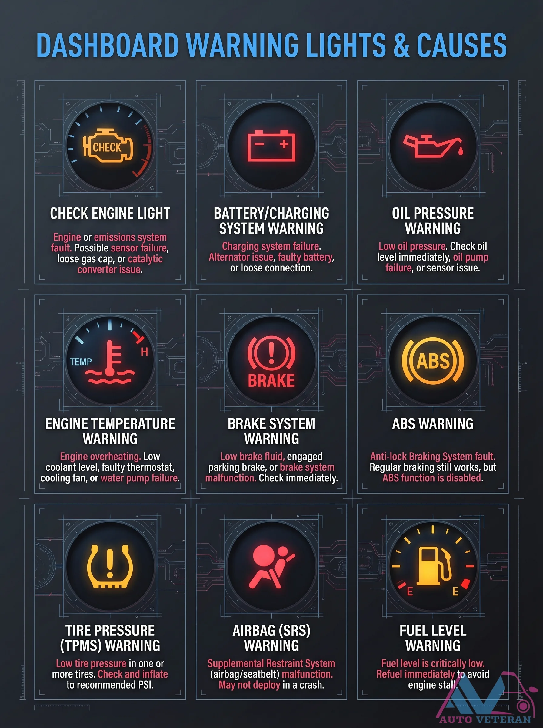
Understanding what triggers your vehicle's dashboard warning lights is crucial for safe operation. The Check Engine Light can indicate engine or emissions system faults, including possible sensor failures, loose gas caps, or catalytic converter issues. The Battery/Charging Warning signals charging system failures, alternator problems, faulty batteries, or loose connections. Oil Pressure Warnings require immediate attention to low oil pressure, prompting checks of oil levels and potential oil pump or sensor failures. Engine Temperature Warnings alert to overheating from low coolant levels, faulty thermostats, cooling fan issues, or water pump failures. Brake System Warnings cover low brake fluid, engaged parking brakes, or brake malfunctions, while ABS Warnings indicate Anti-lock Braking System faults where regular braking remains functional but ABS is disabled. Tire Pressure Warnings notify of low pressure in one or more tires, necessitating inflation to recommended PSI. Airbag Warnings signal Supplemental Restraint System malfunctions that may prevent deployment in crashes. Fuel Level Warnings indicate critically low fuel requiring immediate refueling to avoid engine stall. This comprehensive guide helps drivers interpret these alerts for timely action and vehicle maintenance.
Dashboard Warning Lights Explained Guide
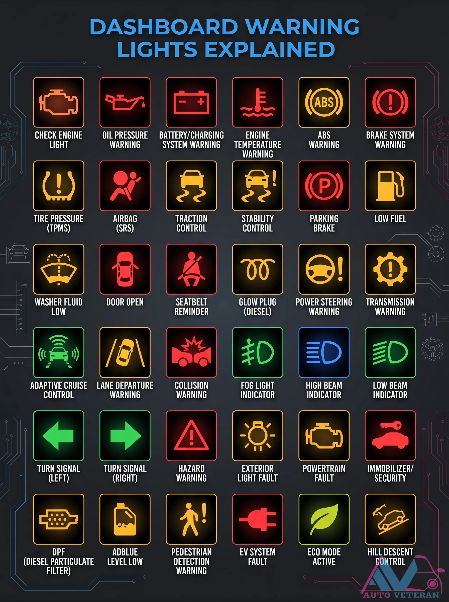
This comprehensive guide details the meaning of various dashboard warning lights, including ABS, check engine, oil pressure, battery charging, engine temperature, tire pressure, airbag, traction control, stability control, parking brake, low fuel, washer fluid, door open, seatbelt, glow plug, power steering, transmission, adaptive cruise, lane departure, collision warning, fog light, high beam, low beam, turn signals, hazard, exterior light fault, powertrain fault, immobilizer security, DPF, AdBlue level, pedestrian detection, EV system fault, eco mode, hill descent control, and auto veteran indicators.
Dashboard Warning Lights Explained with Symbols
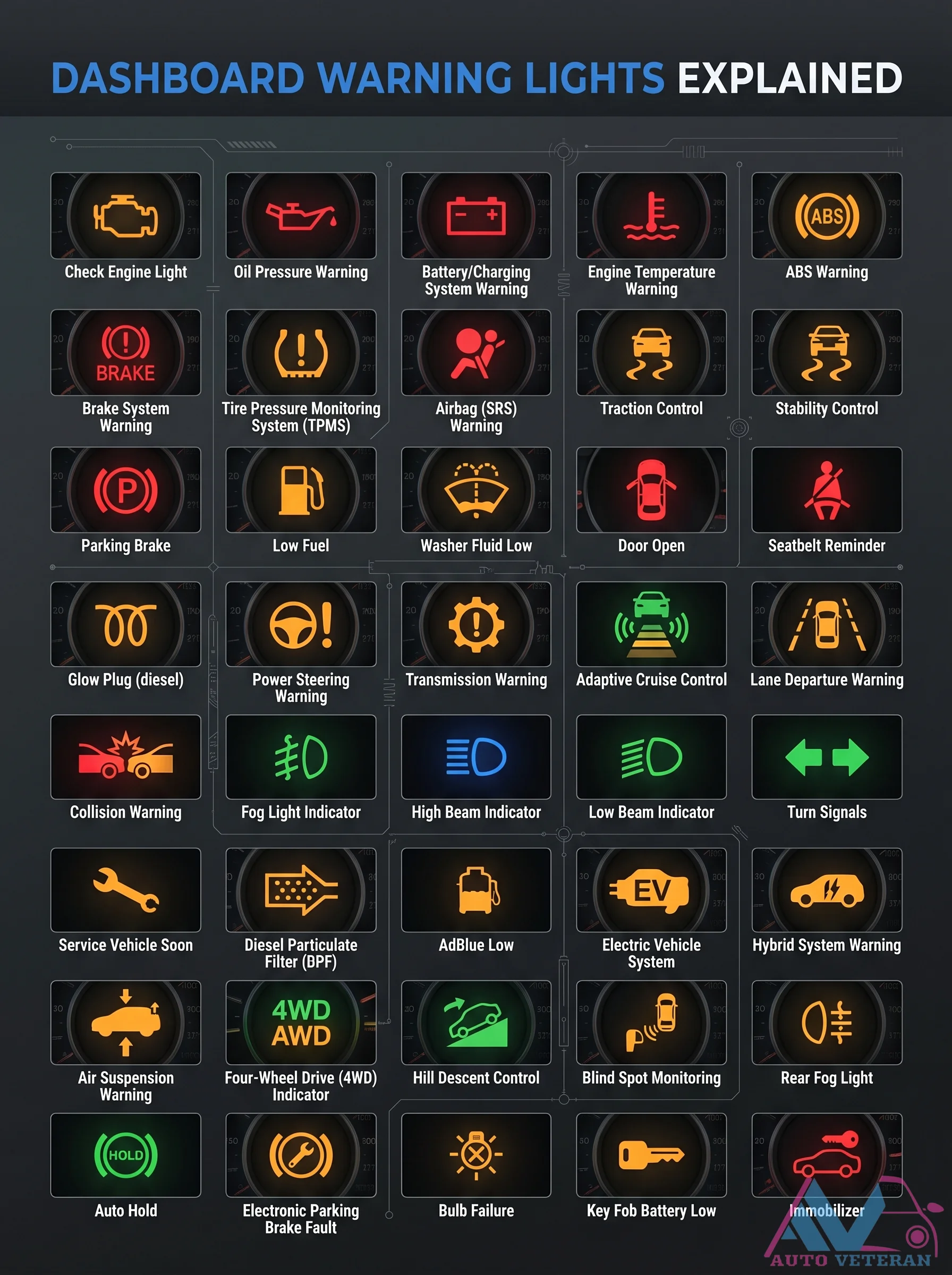
Understanding your vehicle's dashboard warning lights is crucial for safe operation; this comprehensive guide explains the meaning behind common symbols like ABS, Check Engine, Oil Pressure, Battery, and Engine Temperature warnings, along with specialized indicators for systems such as Tire Pressure Monitoring, Airbag, Traction Control, and Stability Control. It also covers diesel specific alerts like Glow Plug and Diesel Particulate Filter, plus modern features including Adaptive Cruise Control, Lane Departure Warning, and Hybrid System warnings, helping drivers quickly identify issues and take appropriate action.
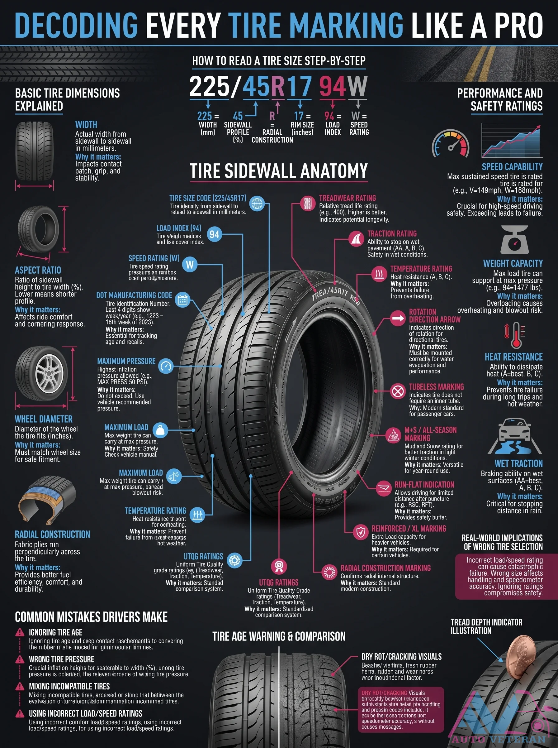
Decoding Every Tire Marking Like a Pro
Understanding the cryptic alphanumeric codes on your tire sidewall unlocks critical safety and performance data. The size code 225/45R17 94W tells you the width in millimeters (225), aspect ratio (45), radial construction (R), wheel diameter in inches (17), load index (94 meaning 1477 lbs max per tire), and speed rating (W up to 168 mph). Beyond size markings, the sidewall reveals manufacturing date, maximum pressure, load ratings, traction grades (AA to C), temperature resistance (A to C), and special icons like directional arrows or run-flat indicators. Knowing how to read these markings helps you avoid common mistakes such as mismatched tires, wrong pressure, or ignoring age and dry rot. Proper selection ensures optimal grip, braking on wet surfaces, heat dissipation, and overall vehicle stability.

Defensive Driving Hazard Awareness Tips
Defensive driving is about expecting the unexpected on the road. Recognize hazardous situations, assume other drivers will make mistakes, and make adjustments when a hazard develops. Look ahead for approaching hazards, watch vehicles to your side and rear, and scan the road before changing speed or direction. Always use your turn signals, drive with your lights on, and stay alert. Good driving combines awareness, anticipation, control, and responsibility to keep everyone safe.
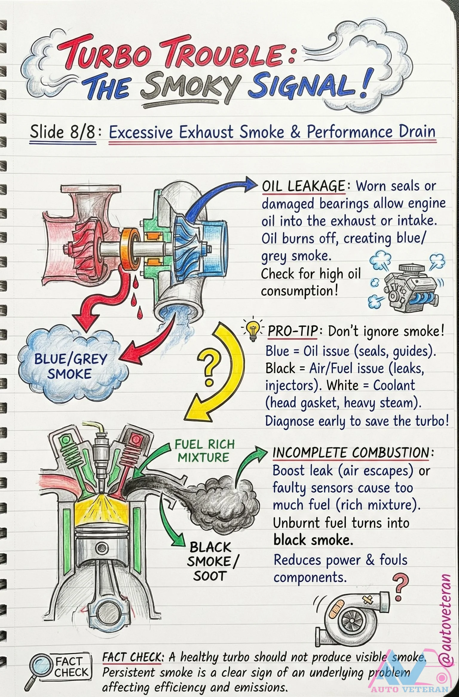
Diagnosing Turbo Problems by Exhaust Smoke Color
Excessive exhaust smoke from a turbocharged engine provides critical diagnostic clues based on its color. Blue or grey smoke indicates oil leakage from worn seals or damaged bearings, leading to high oil consumption. Black smoke signals a rich fuel mixture from boost leaks or faulty sensors, causing incomplete combustion, power loss, and soot buildup. White smoke points to coolant intrusion, often from a head gasket failure. A healthy turbo should not produce visible smoke; persistent smoke reveals underlying efficiency and emissions issues that require immediate attention to prevent further damage.
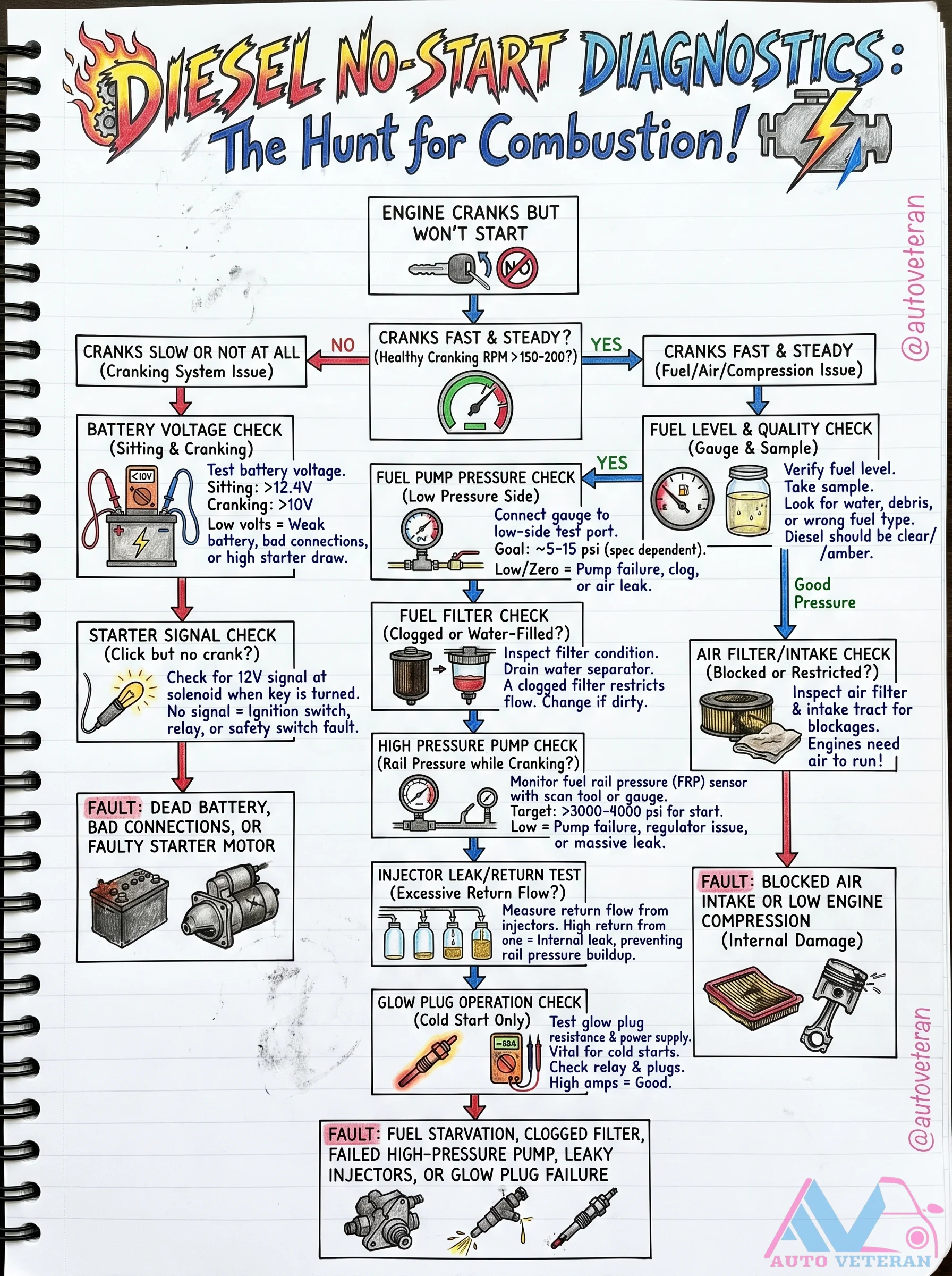
Diesel Cranks No Start Diagnostic Flow
Follow a structured diagnostic tree to pinpoint why a diesel engine cranks but refuses to fire. The process begins by verifying a healthy cranking speed above 150-200 RPM. If cranking is fast and steady, the issue lies in fuel, air, or compression. Checklist steps include battery voltage check during cranking (must be above 10V), fuel pump pressure test (target 5-15 psi), fuel filter inspection for clogs or water, air intake restrictions, high-pressure pump output (rail pressure above 3000-8000 psi), injector leak/return test to detect excessive return flow, and glow plug operation for cold starts. Common culprits: fuel starvation, clogged filter, failed high-pressure pump, leaky injectors, or glow plug failure.
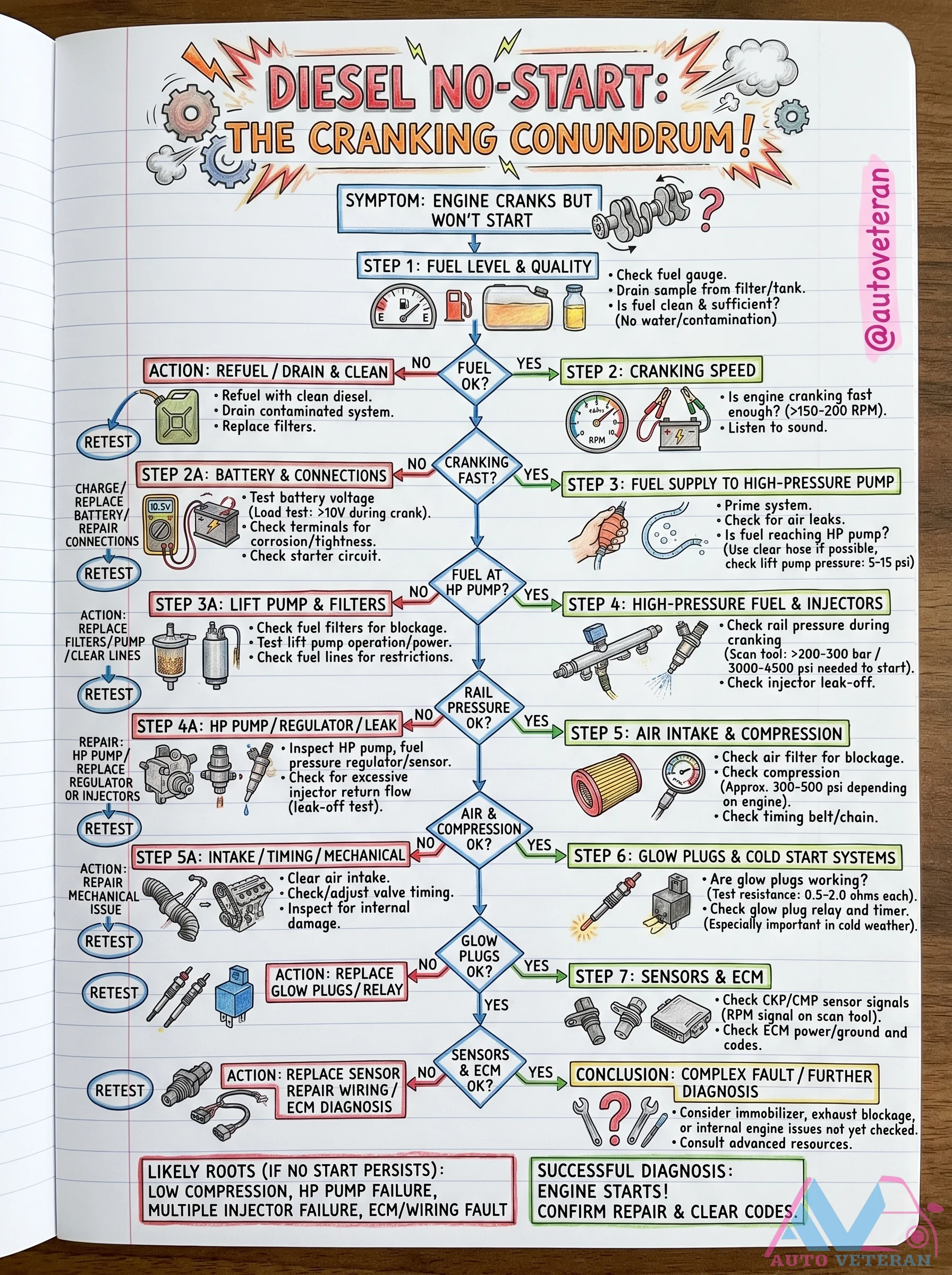
Diesel No-Start Cranking Diagnosis Guide
Systematic 7-step diagnostic flowchart for a diesel engine that cranks but won't start. Start by checking fuel level and quality; if contaminated, drain and clean. Next verify cranking speed above 150-200 RPM; slow cranking points to battery or starter issues. Then ensure fuel supply to the high-pressure pump with lift pump pressure of 5-15 psi. Check rail pressure during cranking must exceed 200-300 bar (3000-4500 psi) for start. Inspect air intake, compression, timing, glow plugs, and sensors like CKP/CMP. Likely root causes include low compression, HP pump failure, multiple injector failure, or ECM wiring fault.
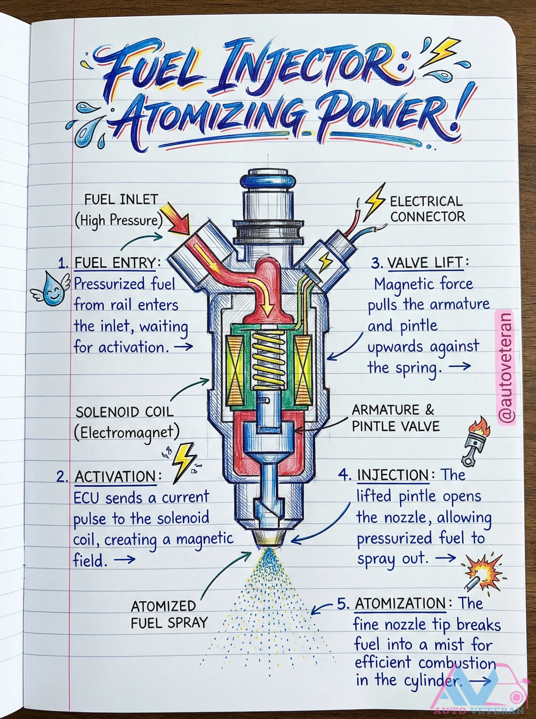
Direct Injection Solenoid Injector Operation Sequence
A direct injection fuel injector uses a solenoid coil to create a magnetic field that lifts the armature and pintle valve against spring pressure; pressurized fuel from the rail enters through the inlet, flows past the opened valve, and atomizes through the fine nozzle tip into a mist for efficient combustion in the cylinder, all controlled by precise ECU current pulses.
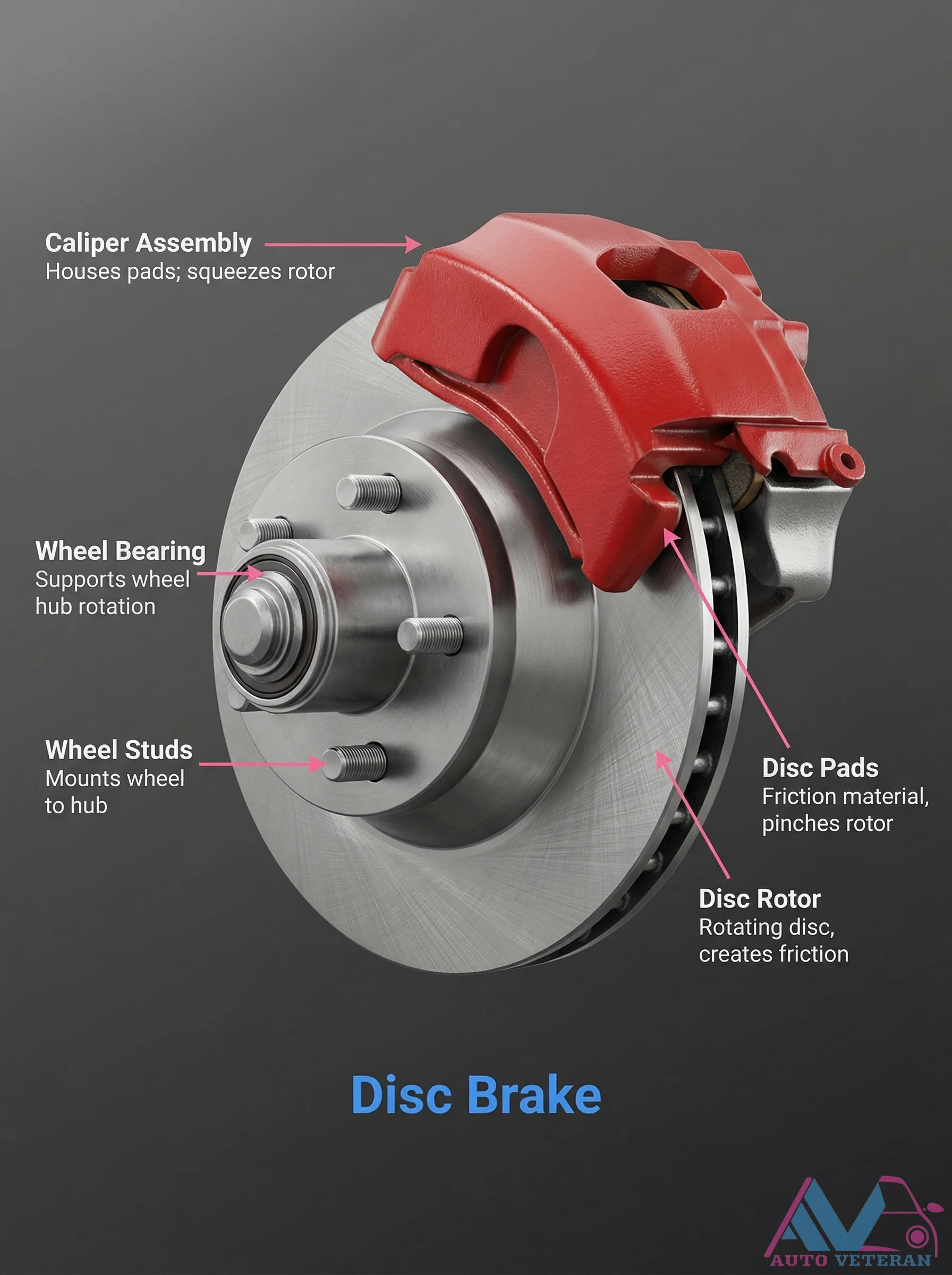
Disc Brake Caliper Assembly and Components
The disc brake system relies on a precise interaction of components; the caliper assembly houses the pads and squeezes the rotor, while the wheel bearing supports hub rotation, wheel studs mount the wheel, disc pads provide friction material to pinch the rotor, and the disc rotor itself rotates to create the necessary friction for stopping power.
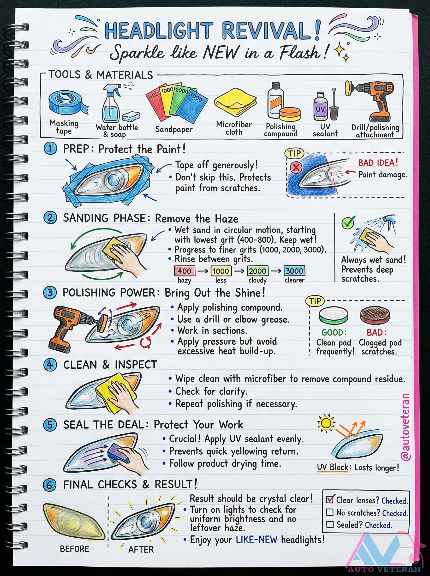
DIY Headlight Restoration Step-by-Step Guide
Revive cloudy headlights to crystal clear condition with this comprehensive restoration process; start by protecting surrounding paint with masking tape, then wet sand using progressive grits from 400 to 3000 in circular motions while keeping the surface wet to prevent scratches. Apply polishing compound with a drill or manual effort, working in sections and avoiding excessive heat buildup, then clean thoroughly with a microfiber cloth. Finish by applying UV sealant to prevent yellowing and ensure long-lasting clarity, resulting in headlights that sparkle like new with improved light output.
Driver Mood Meter Interface
An interactive mood selector for the car's infotainment system presents ten emotional states from Tired to Happy allowing the driver to log their current feeling for personalized comfort adjustments or wellness tracking.
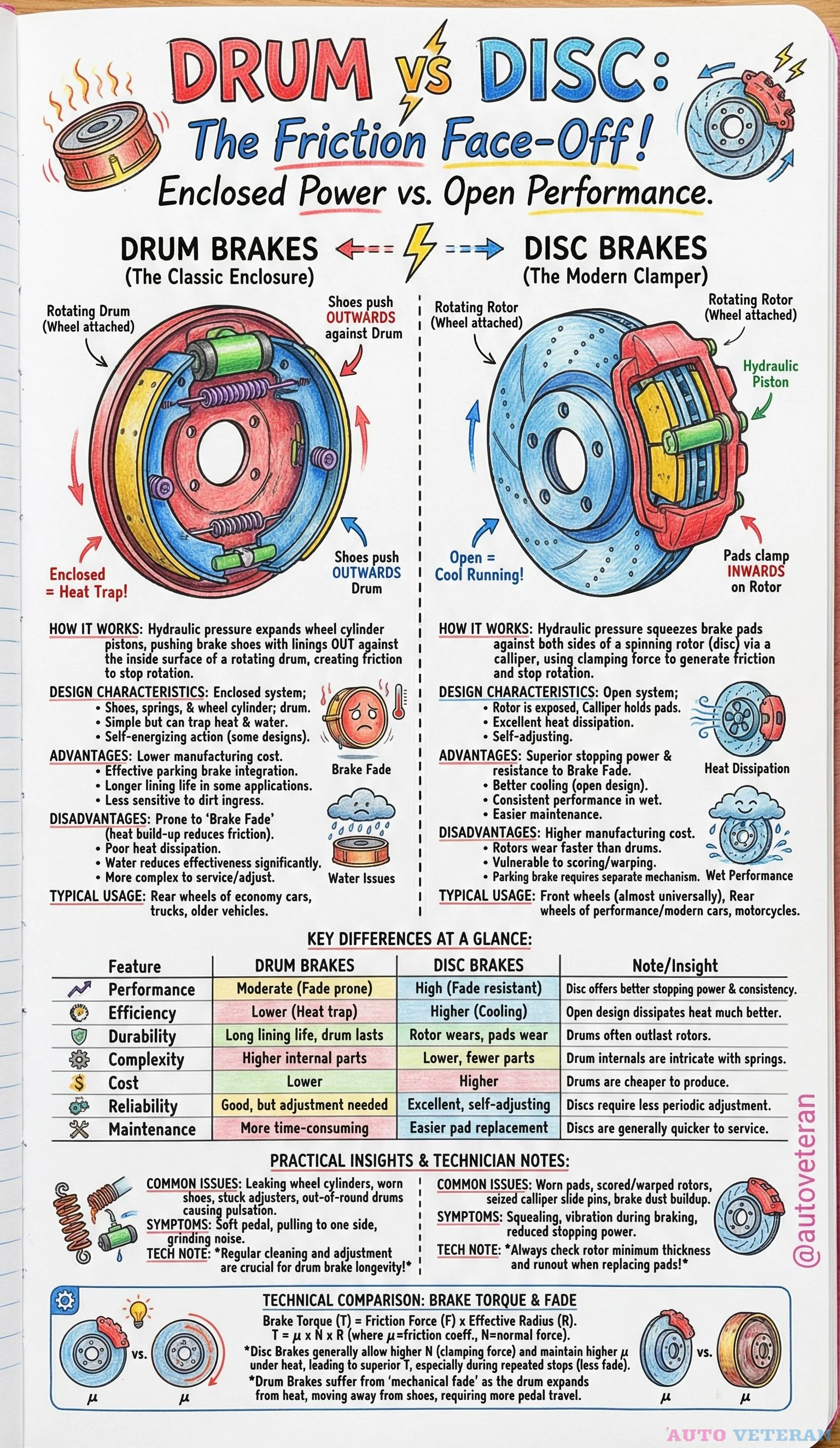
Drum vs Disc Brakes Technical Comparison Guide
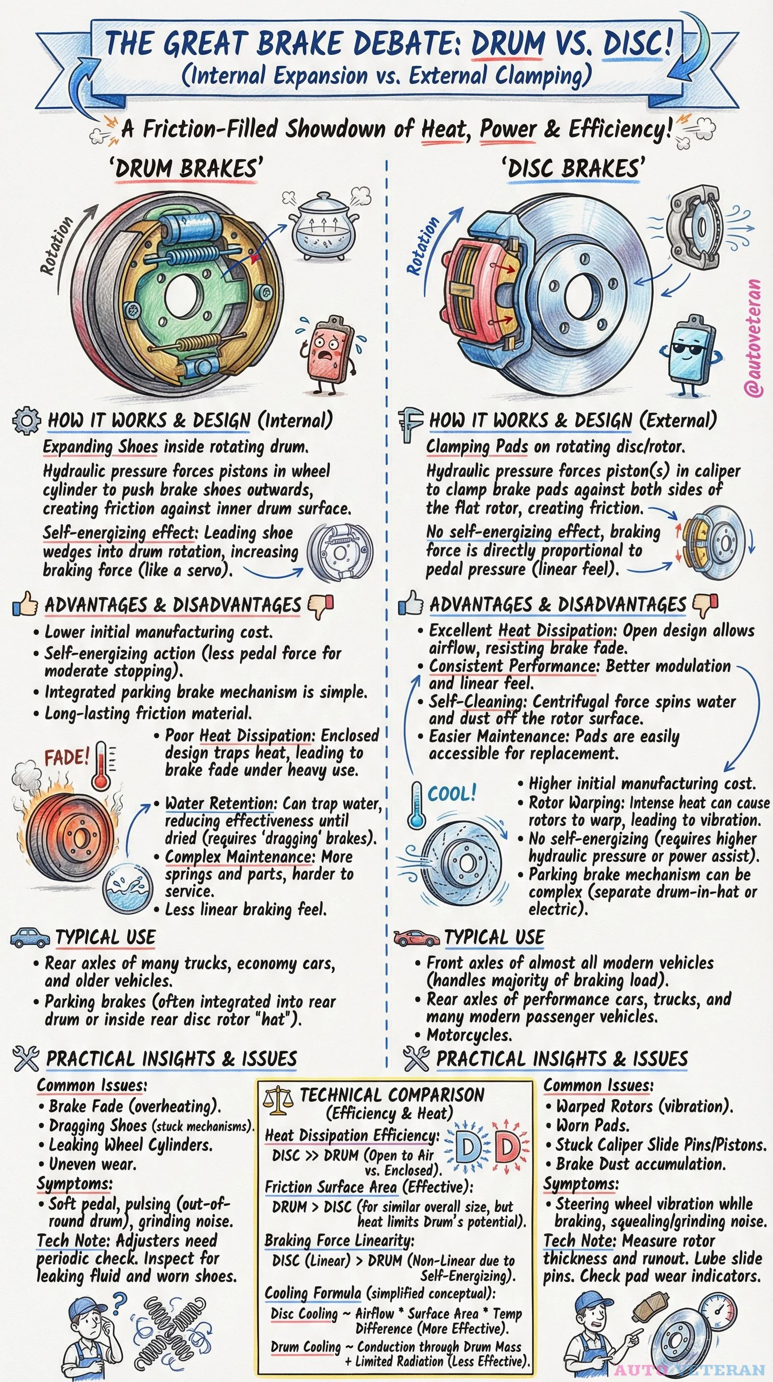
This comprehensive guide details the fundamental differences between drum and disc brake systems, covering their design characteristics, operational mechanics, and real world performance implications. Drum brakes function as enclosed systems where hydraulic pressure expands a wheel cylinder to push brake shoes outward against a rotating drum, creating friction through a self energizing action that can be prone to heat buildup and brake fade. Disc brakes operate as open systems where hydraulic pressure squeezes brake pistons to clamp pads against both sides of a spinning rotor, offering superior heat dissipation and consistent stopping power. Key advantages of drum brakes include lower manufacturing costs, effective parking brake integration, and longer lining life in some applications, while their disadvantages encompass poor heat dissipation, water sensitivity, and more complex maintenance requirements. Disc brakes excel with higher stopping power, better cooling, easier serviceability, and fade resistant performance, though they come with higher manufacturing costs and faster rotor wear. Typical usage patterns show drum brakes commonly on rear wheels of economy cars and older vehicles, while disc brakes dominate front wheels universally and are standard on performance vehicles and motorcycles. Practical insights highlight common issues like scored rotors, seized calipers, and brake dust buildup for disc systems, versus stuck adjusters, out of round drums, and pulling symptoms for drum systems. Technical notes emphasize the importance of regular cleaning and adjustment for drum longevity, and checking rotor minimum thickness during pad replacement for disc systems. The brake torque comparison reveals that disc brakes maintain higher clamping force during repeated stops due to better heat management, while drum brakes suffer from mechanical fade as heat causes drum expansion, increasing pedal travel.
Drum vs Disc Brakes: Design, Performance, and Issues
This detailed comparison examines the fundamental differences between drum and disc brake systems, focusing on their distinct operational principles. Drum brakes function through internal expansion, where hydraulic pressure forces shoes outward against a rotating drum, creating friction with a self-energizing effect that increases force. Disc brakes operate via external clamping, where caliper pistons press pads against both sides of a rotor, offering linear pedal feel directly proportional to pressure. Key advantages of drum brakes include lower manufacturing costs, integrated parking brake mechanisms, and self-energizing action requiring less pedal force. Their disadvantages involve poor heat dissipation in enclosed designs leading to brake fade, water retention, and complex maintenance with springs and parts. Disc brakes excel in heat dissipation through open designs that resist fade, provide consistent performance with better modulation, offer self-cleaning from centrifugal force, and allow easier pad replacement. Their drawbacks include higher initial costs, potential rotor warping from intense heat, and complex parking brake mechanisms. Typical applications show drum brakes on rear axles of trucks, economy cars, and older vehicles, while disc brakes handle front axles of most modern vehicles and rear axles of performance cars. Practical insights reveal common issues: for drum brakes, brake fade from overheating, dragging shoes from stuck mechanisms, and symptoms like soft pedals or grinding noises; for disc brakes, warped rotors causing vibration, stuck caliper components, and symptoms like steering wheel vibration or squealing. Technical notes cover drum brake adjuster checks and fluid inspections versus disc brake rotor measurements and slide pin lubrication. The comparison highlights efficiency factors: disc brakes significantly outperform in heat dissipation due to open airflow, while drum brakes have larger effective friction surface area but limited potential. Braking force linearity differs, with disc systems offering linear response and drum systems showing non-linear self-energizing effects. Cooling mechanisms are conceptually simplified, showing disc cooling through airflow and surface area versus drum conduction with limited radiation.
DTC P0101 MAF Circuit Range/Performance Problem
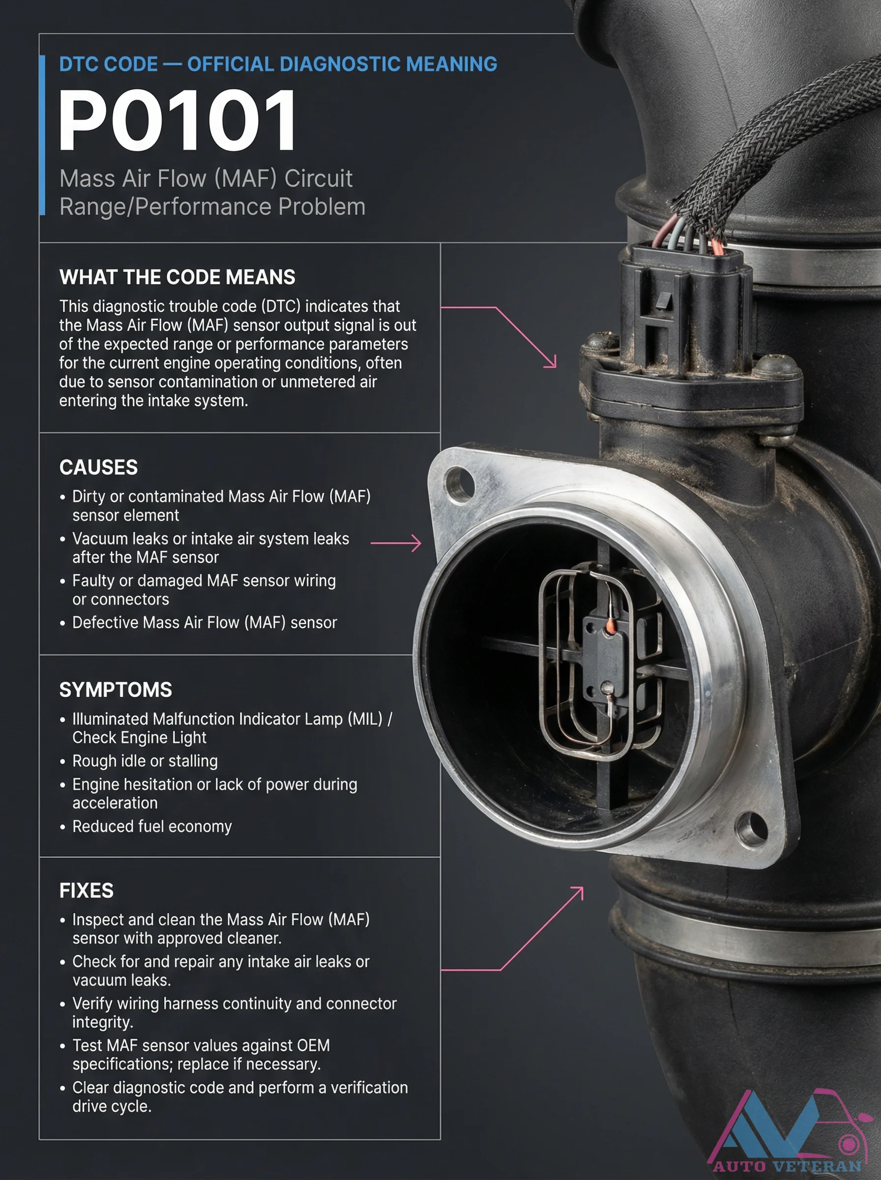
Diagnostic Trouble Code P0101 specifically indicates that the Mass Air Flow sensor signal is outside expected parameters during engine operation. This code typically points to sensor contamination, unmetered air entering the intake system, or wiring issues. Common causes include dirty MAF sensor elements, vacuum leaks downstream of the sensor, damaged wiring or connectors, or a defective sensor itself. Symptoms often manifest as illuminated check engine lights, rough idling, engine hesitation during acceleration, stalling, and reduced fuel economy. Proper diagnosis involves inspecting and cleaning the MAF sensor with approved cleaners, checking for intake air leaks, verifying wiring continuity, testing sensor values against OEM specifications, and clearing codes with verification drive cycles.

DTC P0101 MAF Sensor Range Performance Code
Diagnostic Trouble Code P0101 signals that your vehicle's Mass Airflow Sensor output has deviated from expected parameters, typically caused by sensor contamination or unmetered air entering the intake system. Common symptoms include illuminated check engine lights, rough idling, engine hesitation during acceleration, and reduced fuel economy. This code requires systematic diagnosis including MAF sensor cleaning, intake leak inspection, wiring verification, and sensor testing against OEM specifications before clearing codes and performing verification drive cycles.
DTC P0128 Coolant Thermostat Diagnosis and Fixes
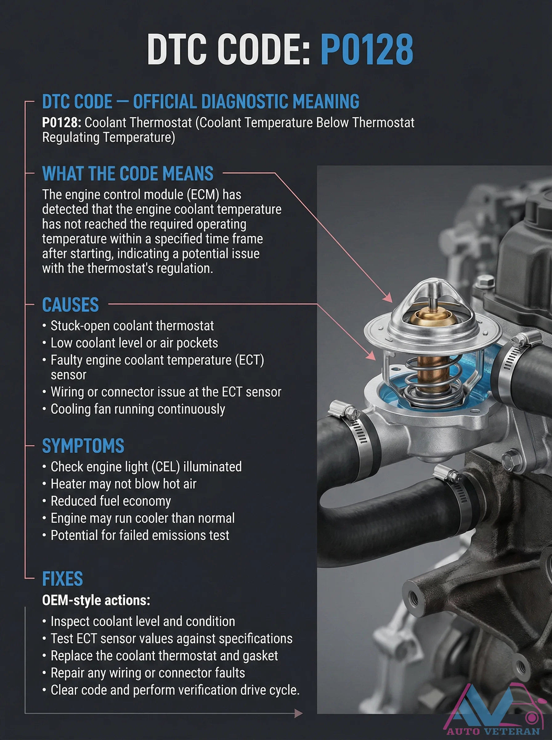
When your engine's computer logs DTC P0128, it indicates the coolant temperature remains below the thermostat's regulating threshold after startup. This diagnostic trouble code points to a thermostat stuck open, low coolant levels, faulty ECT sensor readings, or wiring issues. Symptoms include illuminated check engine lights, insufficient cabin heat, reduced fuel efficiency, and potential emissions test failures. Proper resolution involves checking coolant levels, testing ECT sensor specifications, replacing the thermostat and gasket, and clearing codes with a verification drive cycle.
DTC P0171 System Too Lean Bank 1 Diagnosis
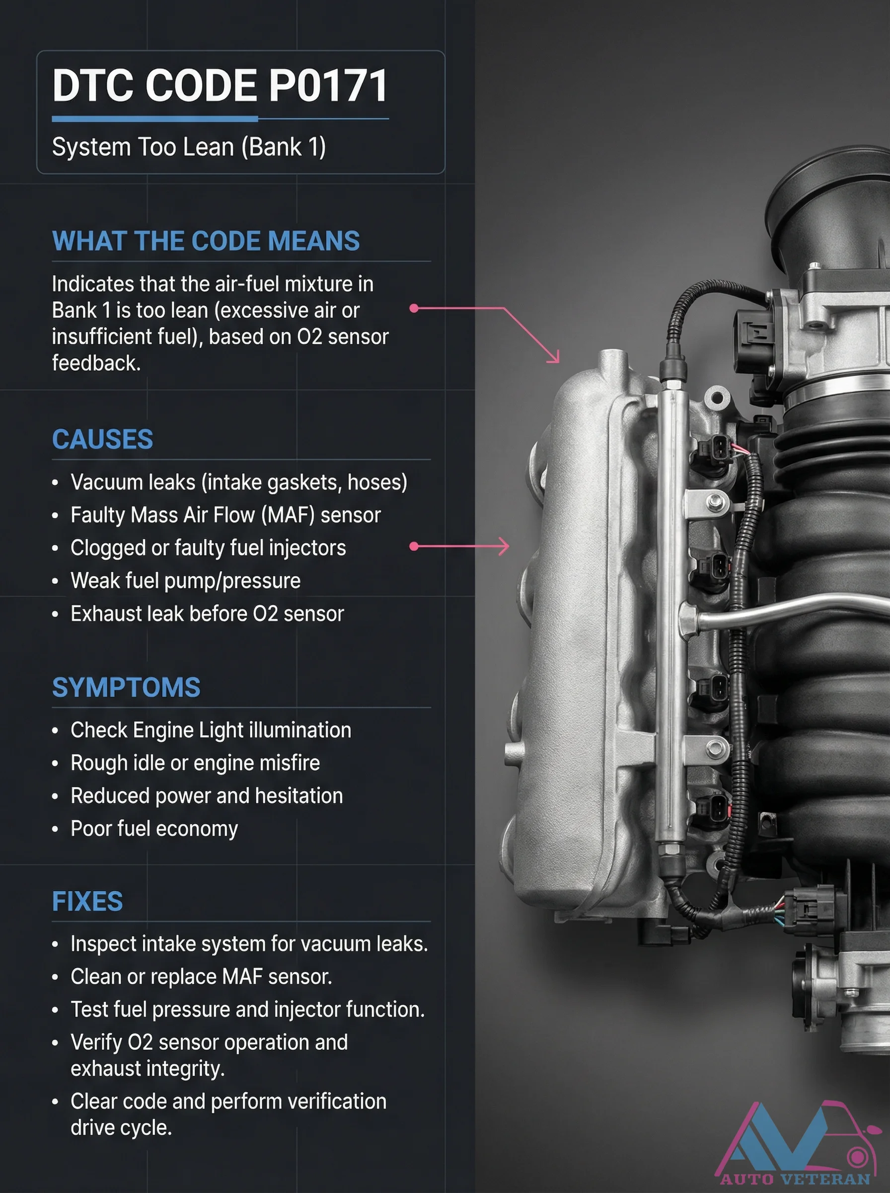
When your vehicle's diagnostic system reports DTC P0171, it indicates the air fuel mixture in Bank 1 has become excessively lean, meaning there's too much air or insufficient fuel entering the combustion chamber. This condition triggers immediate symptoms including check engine light illumination, rough idle or engine misfires, noticeable power reduction with hesitation during acceleration, and decreased fuel efficiency. The root causes typically involve vacuum leaks from intake gaskets or hoses, a faulty mass airflow sensor providing incorrect readings, clogged or malfunctioning fuel injectors, weak fuel pump pressure, or exhaust leaks occurring before the oxygen sensor. Proper diagnosis requires inspecting the entire intake system for vacuum leaks, cleaning or replacing the MAF sensor, testing fuel pressure and injector functionality, verifying oxygen sensor operation and exhaust integrity, then clearing the code and completing a verification drive cycle to confirm resolution.
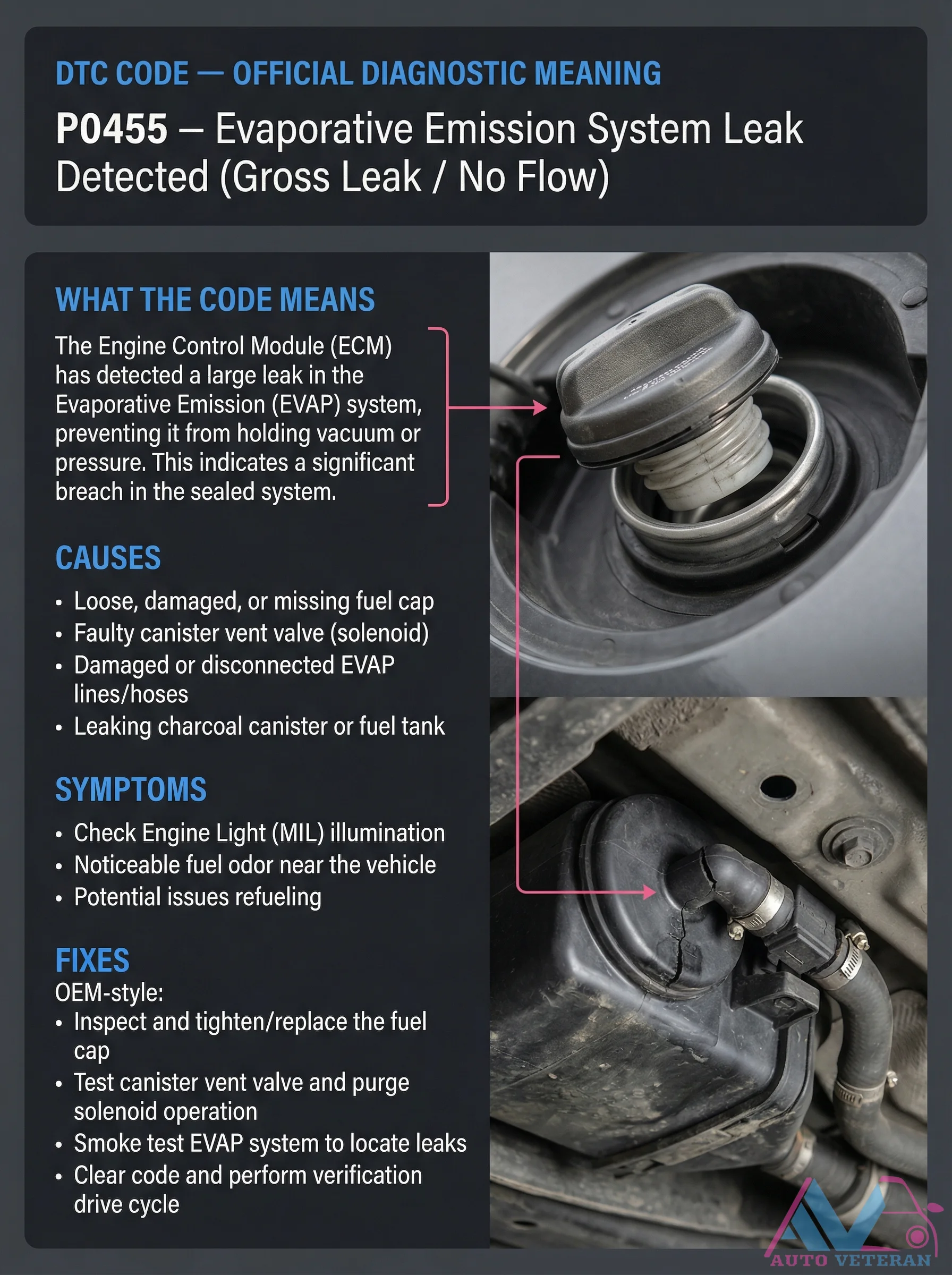
DTC P0455 EVAP Gross Leak Causes and Symptoms
Diagnostic Trouble Code P0455 signals a gross leak in the Evaporative Emission system, where the Engine Control Module detects a major breach preventing proper vacuum or pressure retention. This condition typically manifests through a persistent Check Engine Light, noticeable fuel odors around the vehicle, and potential refueling difficulties. Common culprits include loose or damaged fuel caps, faulty canister vent valves, compromised EVAP lines or hoses, and leaks in the charcoal canister or fuel tank assembly. Proper diagnosis involves systematic inspection of the fuel cap, testing vent and purge solenoid functionality, and conducting smoke tests to pinpoint leak locations before clearing codes and completing verification drive cycles.