Interactive Explorer
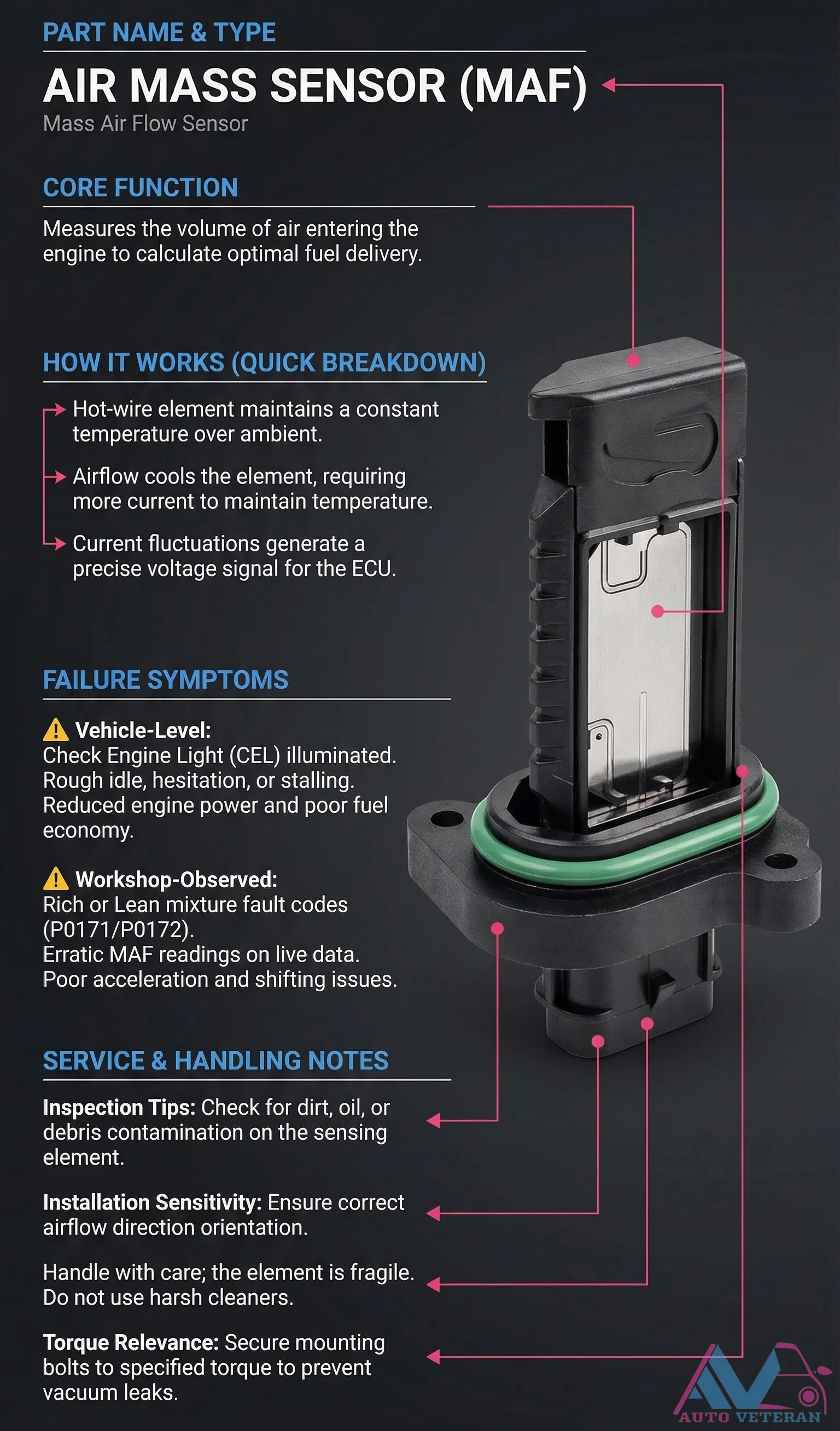
MAF Sensor Hot-Wire Failure Symptoms and Service Notes
When the hot-wire element inside your Mass Airflow Sensor fails, it triggers specific vehicle level symptoms including check engine light illumination, rough idle, hesitation, stalling, reduced engine power, and poor fuel economy. Workshop observations reveal rich or lean mixture fault codes like P0171 and P0172, erratic MAF readings on diagnostic data, and poor acceleration with shifting issues. Proper service requires careful inspection for dirt, oil, or debris contamination on the sensing element, correct airflow direction orientation during installation, gentle handling due to the element's fragility, avoidance of harsh cleaners, and securing mounting bolts to specified torque to prevent vacuum leaks.
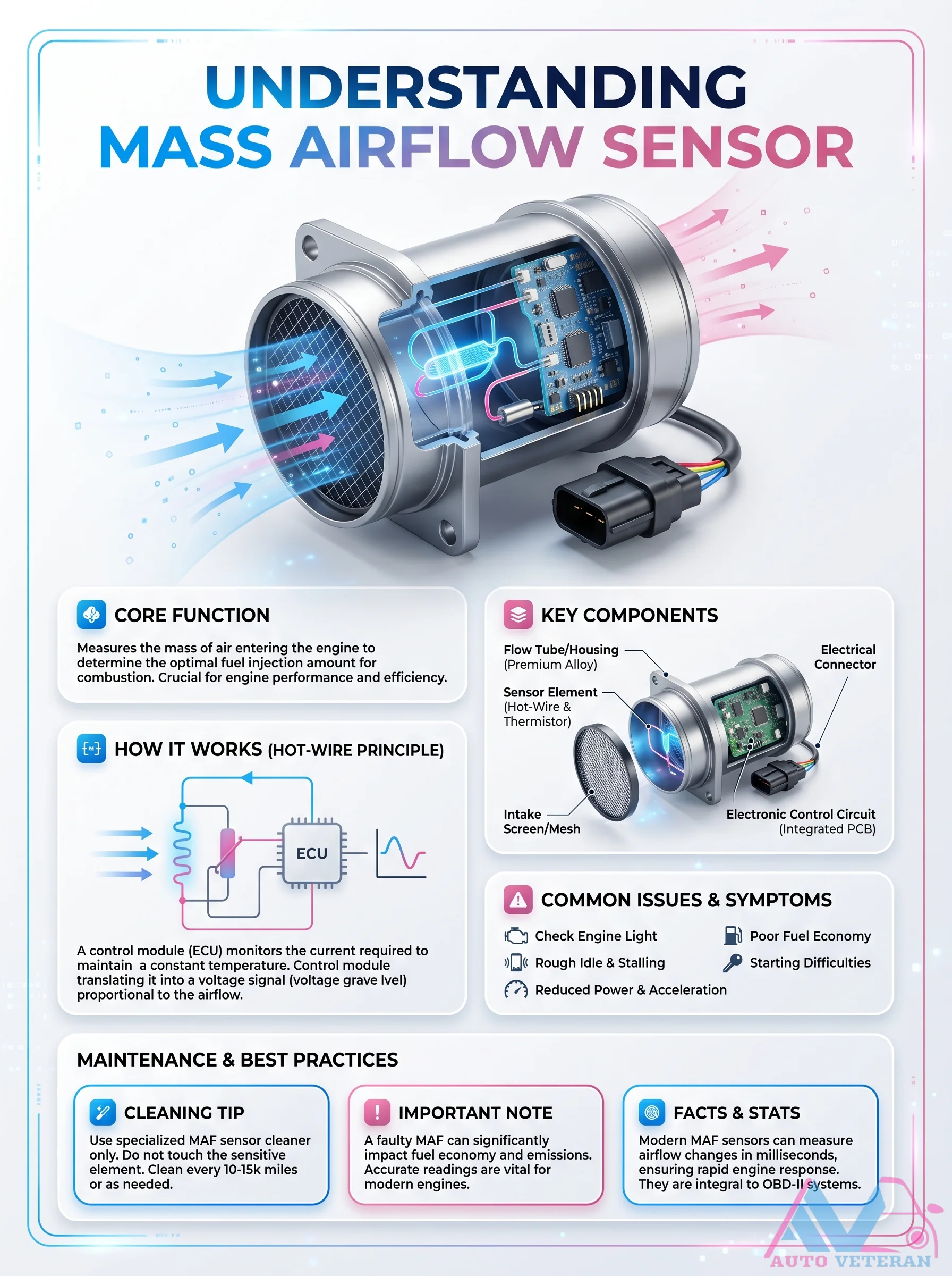
MAF Sensor Hot-Wire Principle and Issues
This infographic breaks down the Mass Airflow Sensor's core function using the hot-wire principle, where the ECU monitors current needed to keep a wire at constant temperature; translating airflow into a voltage signal. Common symptoms include poor fuel economy, rough idle, stalling, starting difficulties, and reduced power. Maintenance tips emphasize using specialized cleaner and avoiding touching the sensitive element. Cleaning every 10 to 15k miles helps prevent faults that impact fuel economy and emissions.
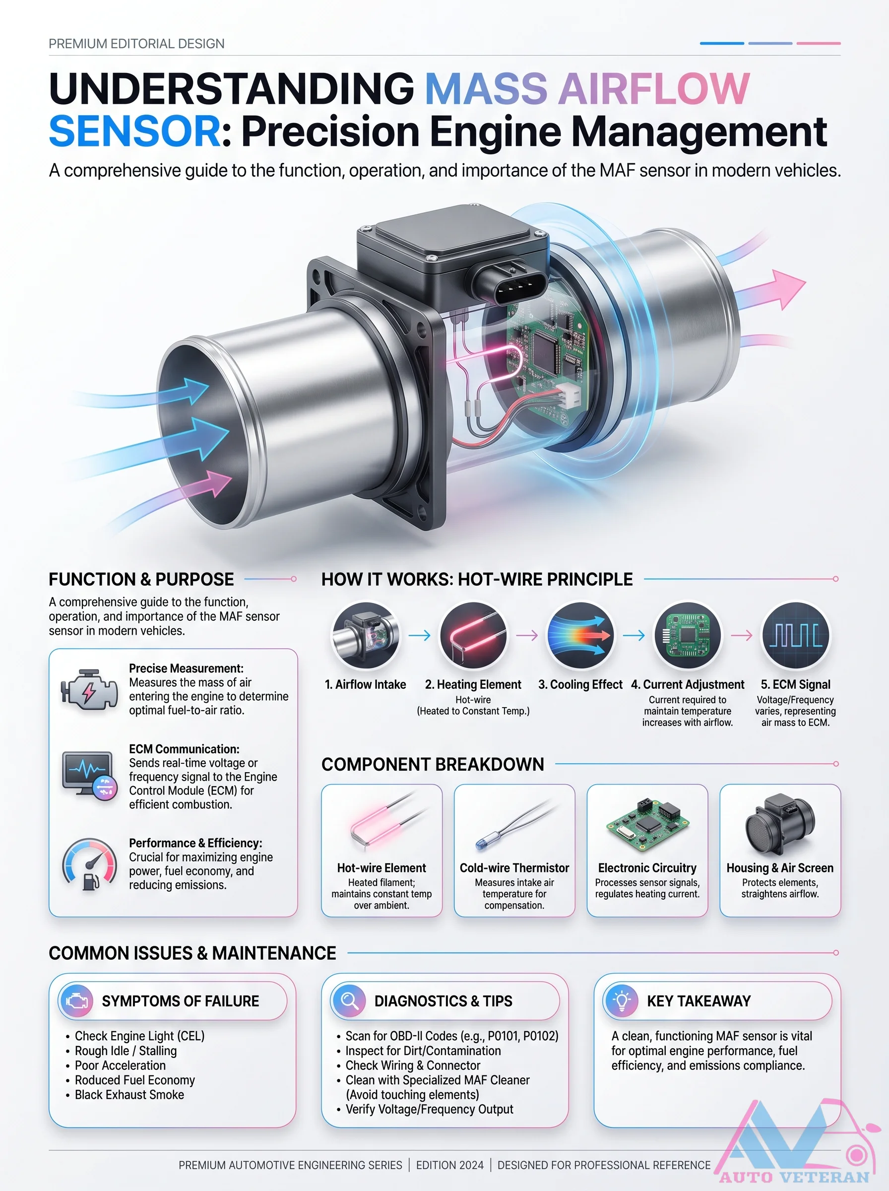
MAF Sensor Hot-Wire Principle Guide
Mass Airflow Sensor operation relies on the hot-wire principle; a heated filament cools as intake air passes over it, and the ECM adjusts current to maintain constant temperature. This voltage or frequency signal determines precise fuel delivery for optimal combustion. The design includes a hot-wire element, cold-wire thermistor, and electronic circuitry housed within an air screen. Common failure symptoms include check engine light with P0101/P0102 codes, rough idle, stalling, poor acceleration, and black exhaust smoke. Diagnostics involve scanning for codes, inspecting wiring connectors, and cleaning with specialized MAF cleaner while avoiding element contact. Proper MAF function is critical for engine performance, fuel economy, and emissions compliance.
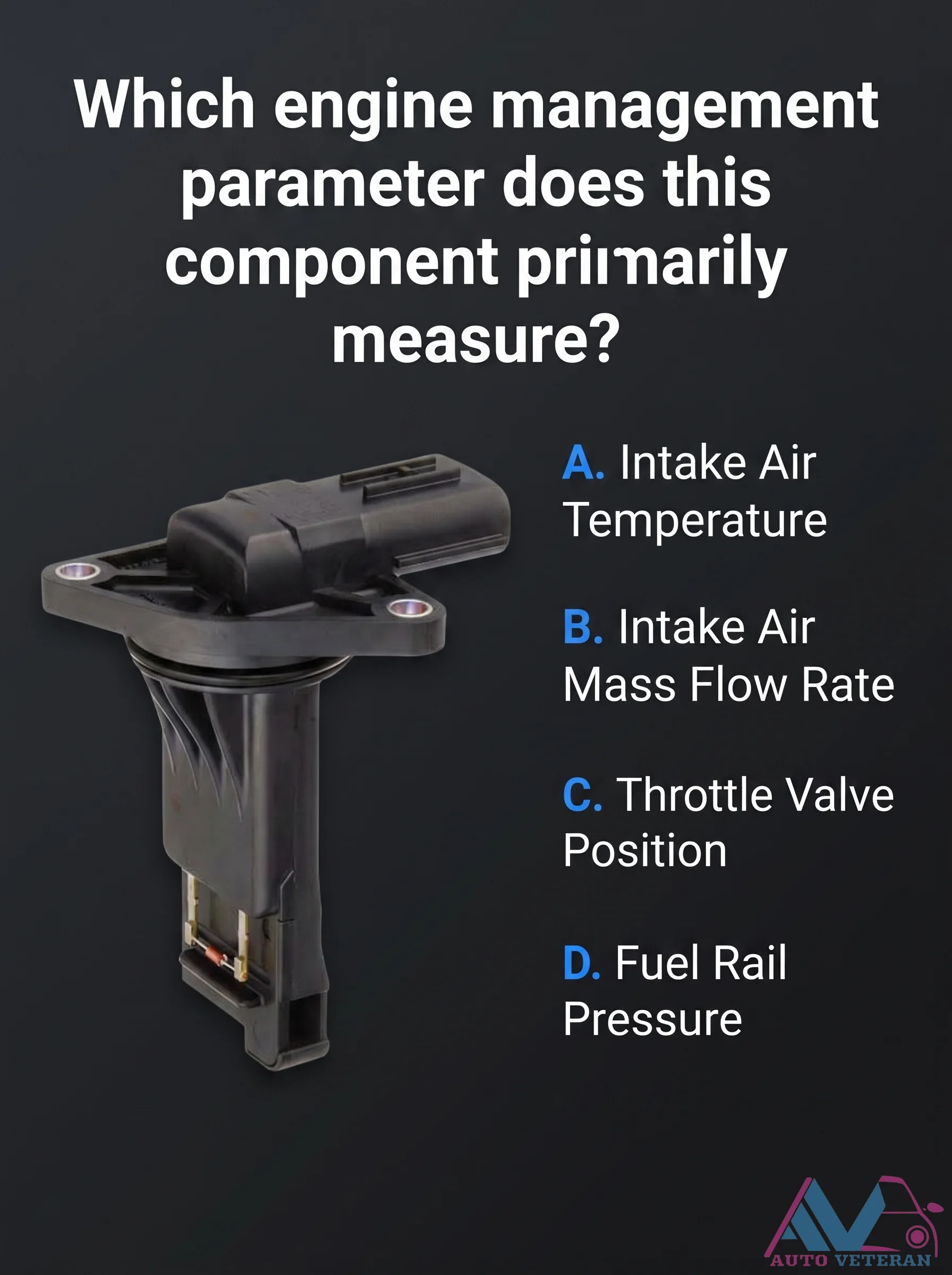
MAF Sensor Parameter Measurement Question
This diagnostic question tests your knowledge of the Mass Airflow Sensor's primary function: measuring the Intake Air Mass Flow Rate. While it may also include an Intake Air Temperature sensor, the core parameter is the flow rate, critical for correct air-fuel mixture calculation.
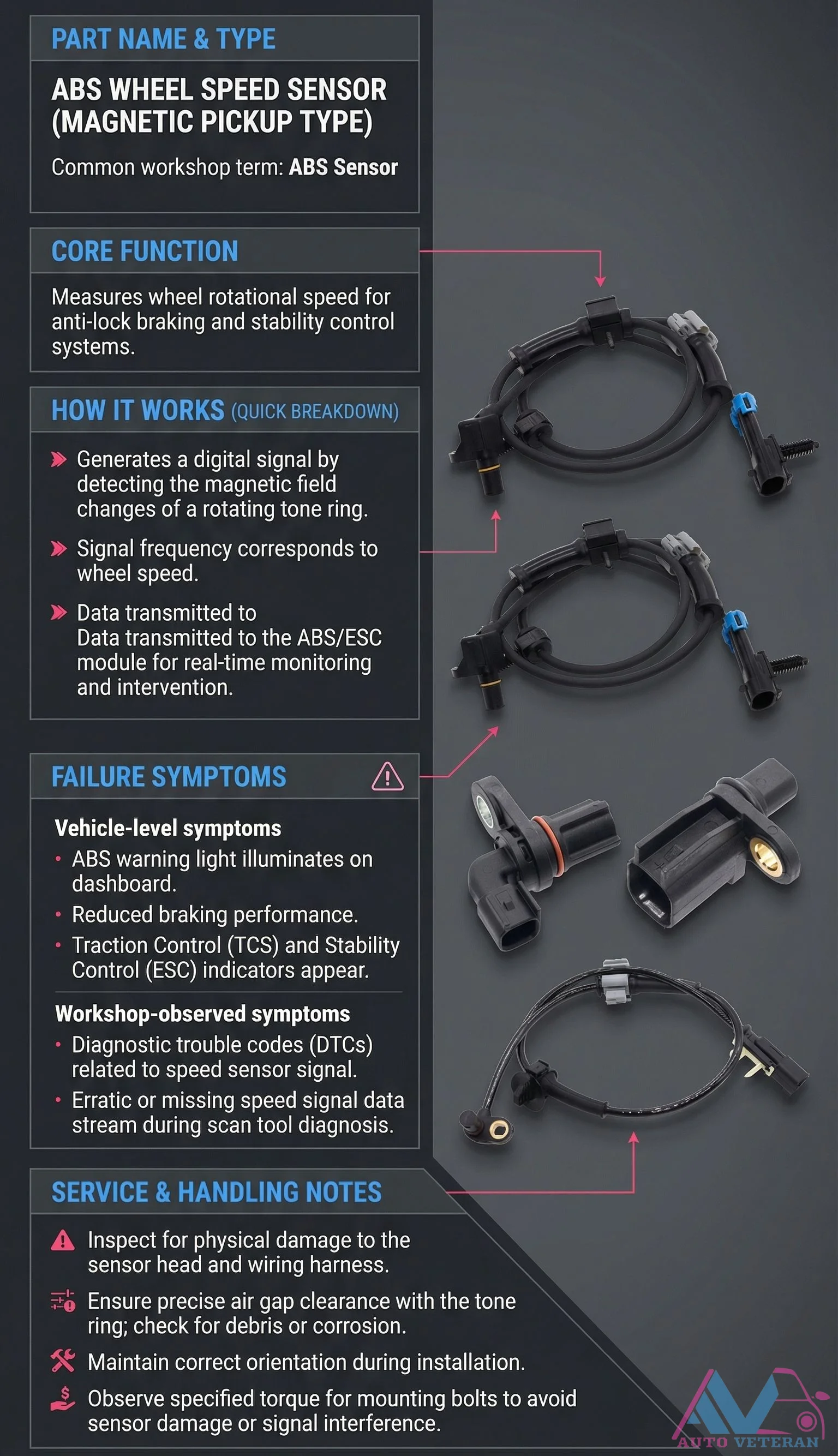
Magnetic ABS Wheel Speed Sensor Failure Symptoms
When a magnetic pickup type ABS wheel speed sensor fails, it directly impacts your vehicle's safety systems. The ABS warning light illuminates on the dashboard, indicating reduced braking performance and potential loss of traction control and stability control functions. Workshop diagnostics reveal trouble codes related to speed sensor signals, with erratic or missing data streams during scan tool analysis. Proper service requires inspecting for physical damage to the sensor head and wiring harness, ensuring precise air gap clearance with the tone ring, maintaining correct orientation during installation, and observing specified torque for mounting bolts to prevent sensor damage or signal interference.
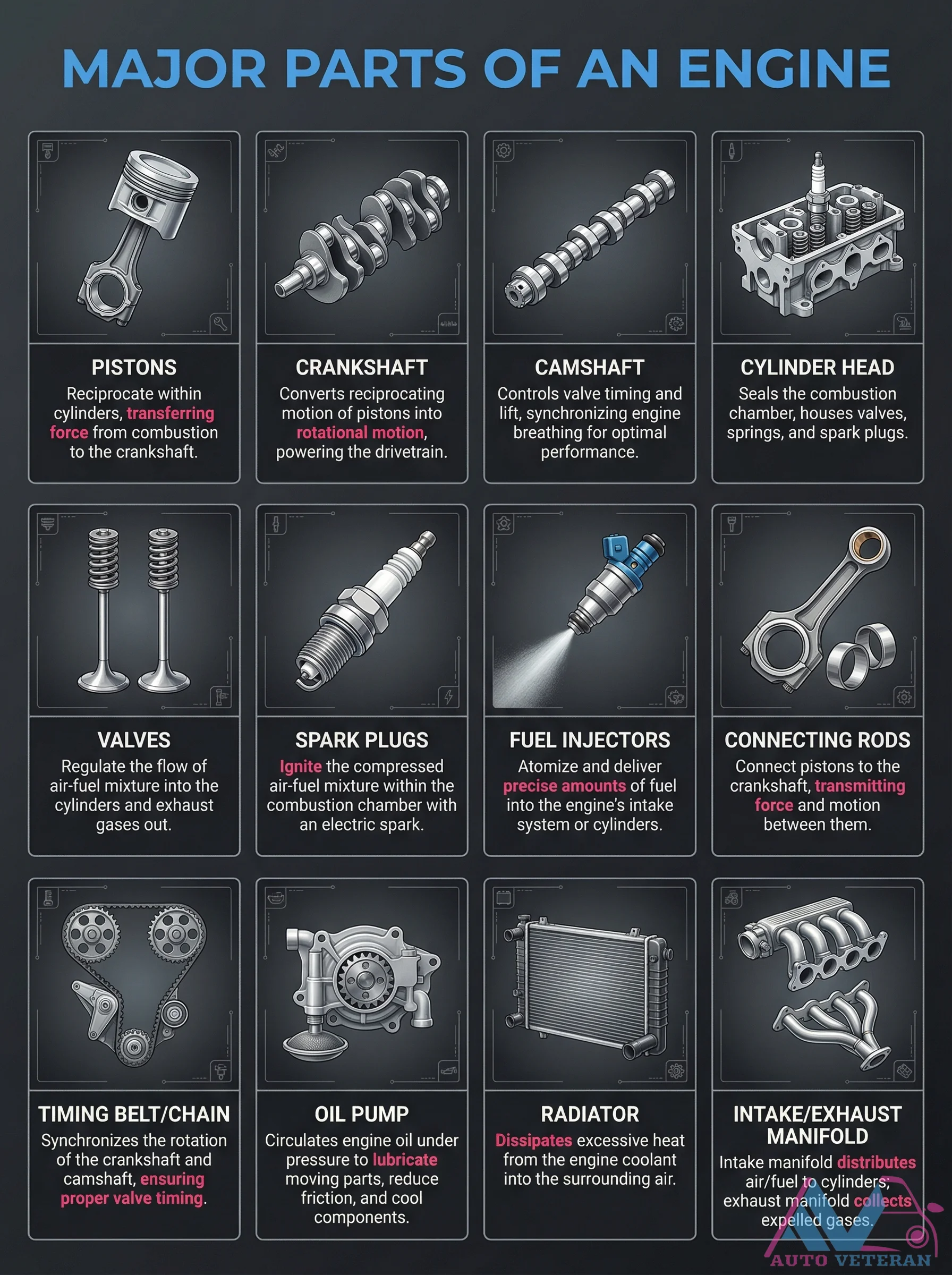
Major Engine Parts Diagram and Functions
This detailed breakdown explains the critical components that make an internal combustion engine work. Pistons reciprocate within cylinders to transfer combustion force to the crankshaft, which converts this motion into rotational power for the drivetrain. The camshaft precisely controls valve timing and lift to optimize engine breathing, while the cylinder head seals the combustion chamber and houses valves, springs, and spark plugs. Valves regulate airflow, spark plugs ignite the mixture, fuel injectors deliver precise fuel amounts, and connecting rods transmit force between pistons and crankshaft. The timing belt synchronizes crankshaft and camshaft rotation, the oil pump circulates lubricant, the radiator dissipates heat, and intake/exhaust manifolds manage air and gas flow.
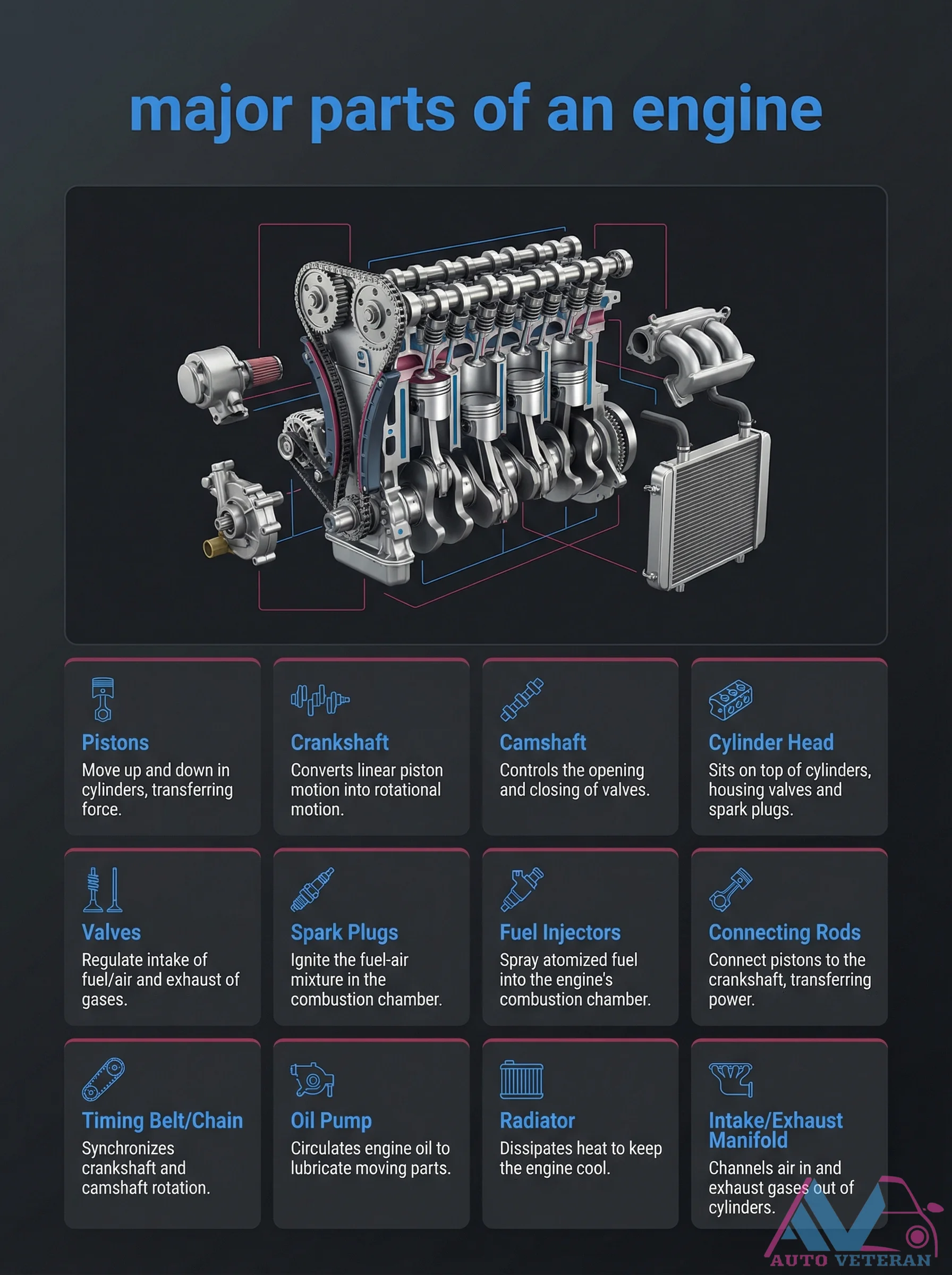
Major Engine Parts Diagram with Functions
This detailed breakdown illustrates the core components that make an internal combustion engine work, including pistons that move up and down in cylinders to transfer force, a crankshaft that converts linear motion into rotational power, and a camshaft that controls valve timing. The diagram also shows cylinder heads housing valves and spark plugs, valves regulating intake and exhaust gases, spark plugs igniting the fuel-air mixture, fuel injectors spraying atomized fuel, connecting rods linking pistons to the crankshaft, timing belts or chains synchronizing rotation, oil pumps circulating lubrication, radiators dissipating heat, and intake or exhaust manifolds channeling air and gases.
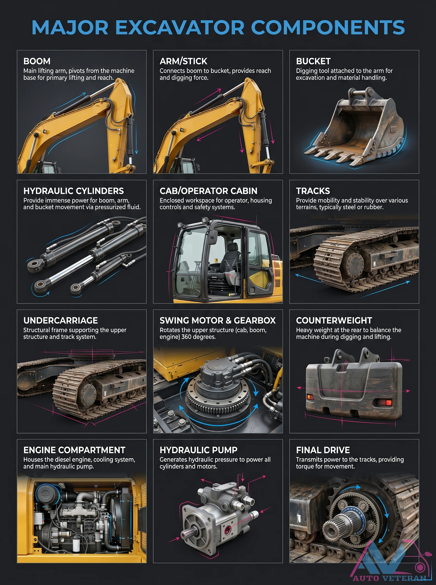
Major Excavator Components Labeled Diagram
A comprehensive breakdown of an excavators key systems shows how the boom arm and stick connect the bucket for digging and reach while hydraulic cylinders drive movement through pressurized fluid. The enclosed cab provides operator controls and safety features while tracks mounted on the undercarriage deliver mobility and stability. A swing motor enables full 360 degree rotation of the upper structure and the counterweight balances heavy digging forces. The engine compartment houses the diesel engine and hydraulic pump which generates power for all cylinders and motors. Final drives transmit torque directly to the tracks for smooth movement across rugged terrain.
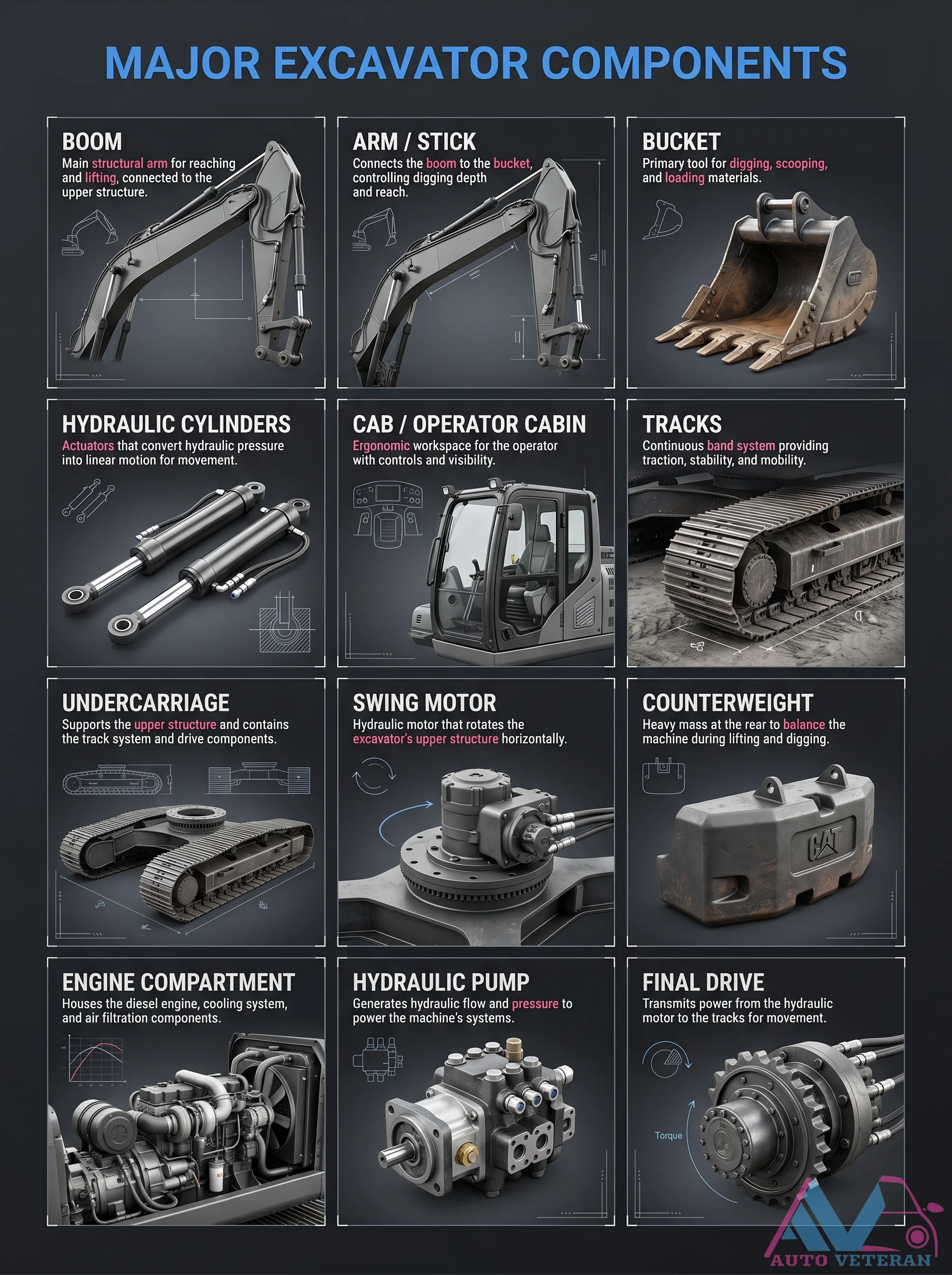
Major Excavator Components Overview
This detailed breakdown labels the key structural and functional parts of an excavator. The boom, arm (or stick), and bucket form the primary digging assembly; the boom reaches, the arm controls depth, and the bucket scoops and loads material. Hydraulic cylinders convert fluid pressure into linear motion for these movements. The cab provides an ergonomic operator workspace with controls and visibility. Tracks mounted on the undercarriage enable stability and mobility. A swing motor rotates the upper structure horizontally, while a counterweight at the rear balances the machine during lifting and digging. The engine compartment houses the diesel engine, cooling system, and air filtration. A hydraulic pump generates flow and pressure to power all systems, and final drives transmit power from the hydraulic motors to the tracks for movement.
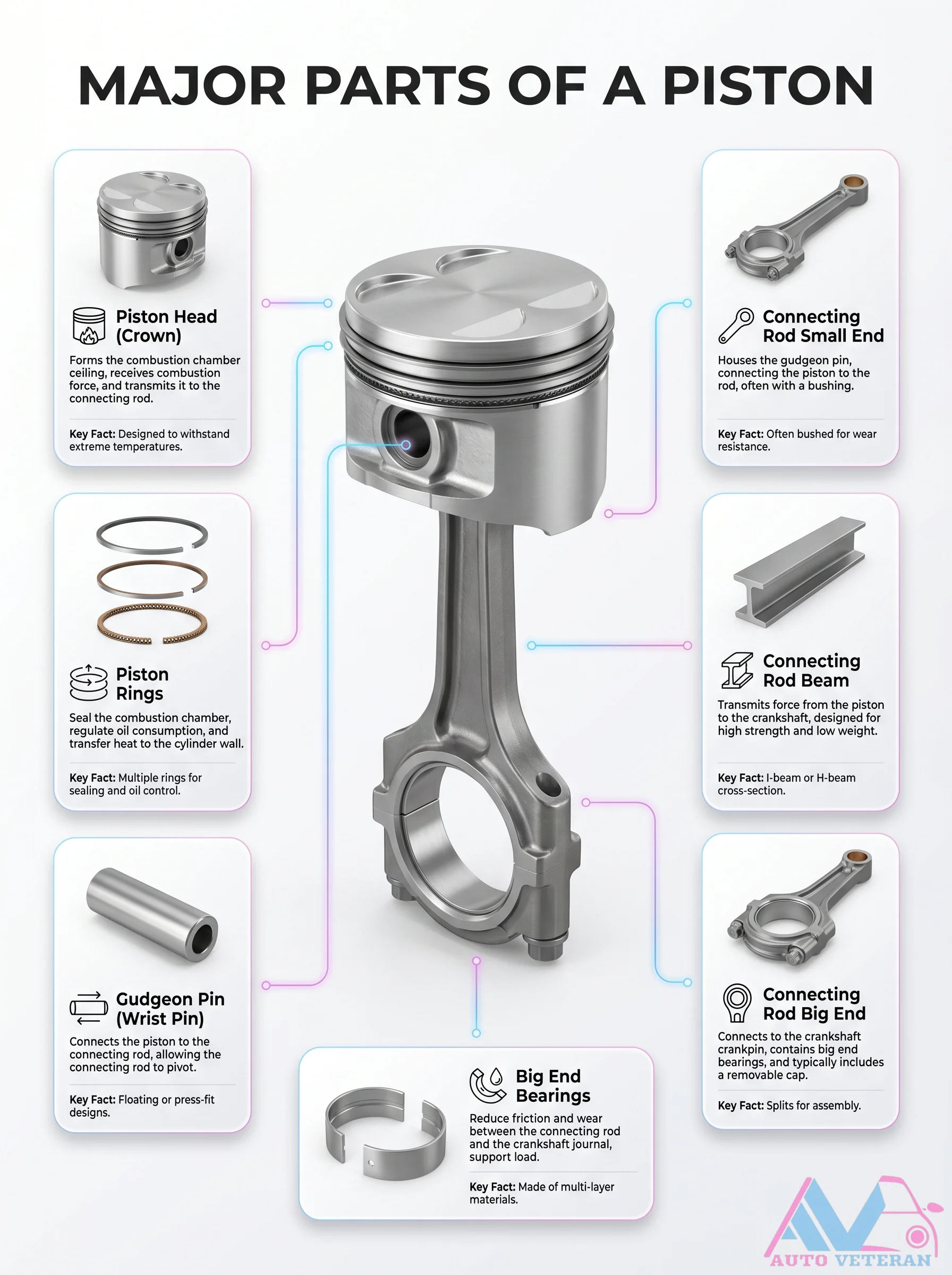
Major Piston Parts Breakdown
This illustration maps the key components of an internal combustion engine piston: the crown which forms the combustion chamber top, the connecting rod with its small and big ends housing the gudgeon pin and bearings, the beam transmitting force to the crankshaft, and the multiple rings ensuring sealing and oil control. The gudgeon pin connects piston to rod, while the big end with removable cap attaches to the crankshaft. Bearings reduce friction and wear at the big end journal. Key facts note the crown withstands extreme conditions, the beam uses I- or H-section for strength, and rings seal the cylinder wall.
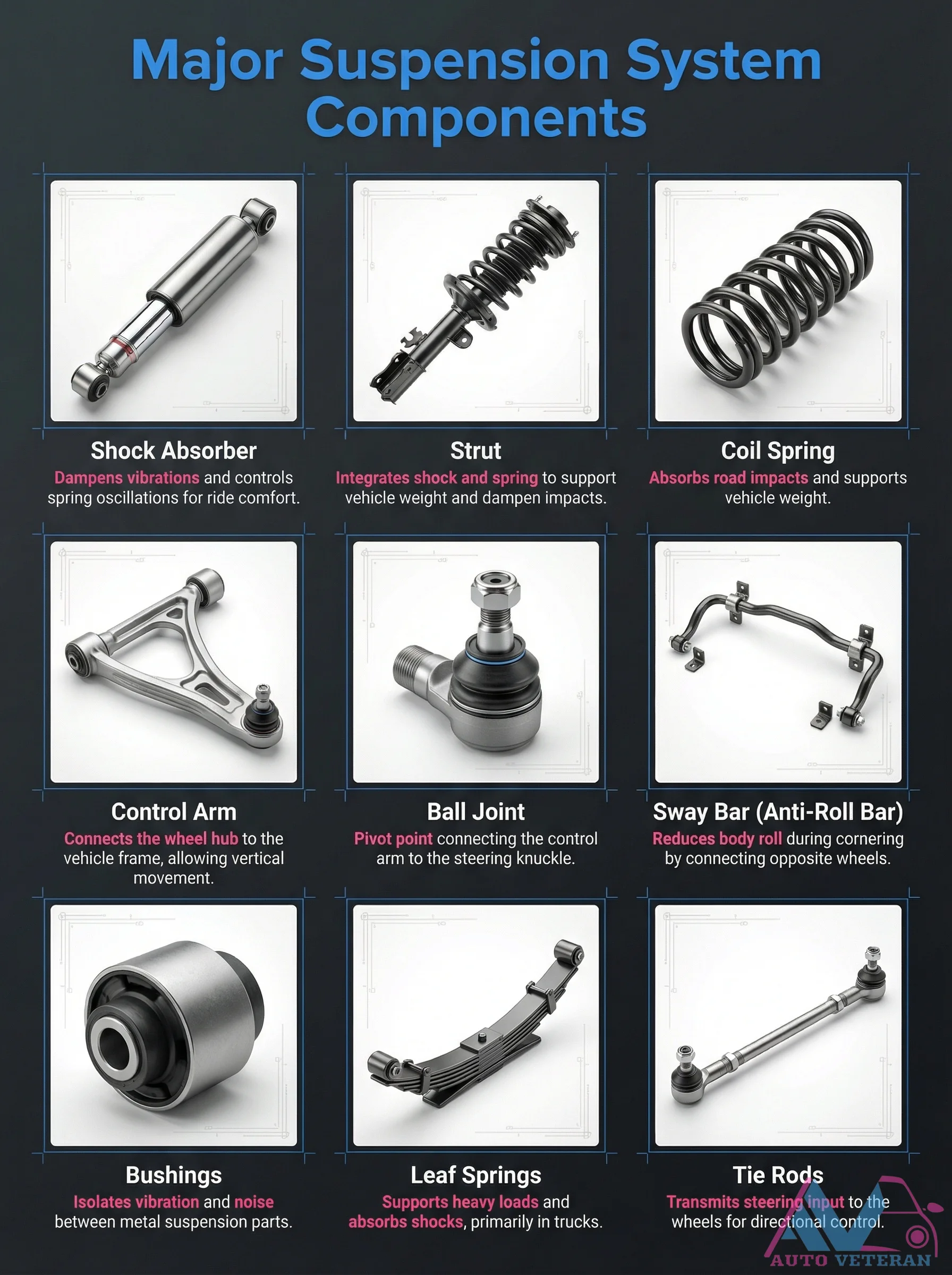
Major Suspension System Components and Functions
This comprehensive diagram illustrates the essential components of a vehicle's suspension system, detailing their specific functions. Key elements include shock absorbers that dampen vibrations for ride comfort, struts that integrate shock and spring functions to support vehicle weight, coil springs that absorb road impacts, control arms that connect wheel hubs to the frame, ball joints that serve as pivot points between control arms and steering knuckles, anti-roll bars that reduce body roll during cornering, bushings that isolate vibration between metal parts, leaf springs that support heavy loads in trucks, and tie rods that transmit steering input for directional control. Understanding how these components work together provides insight into vehicle stability, handling, and comfort characteristics.
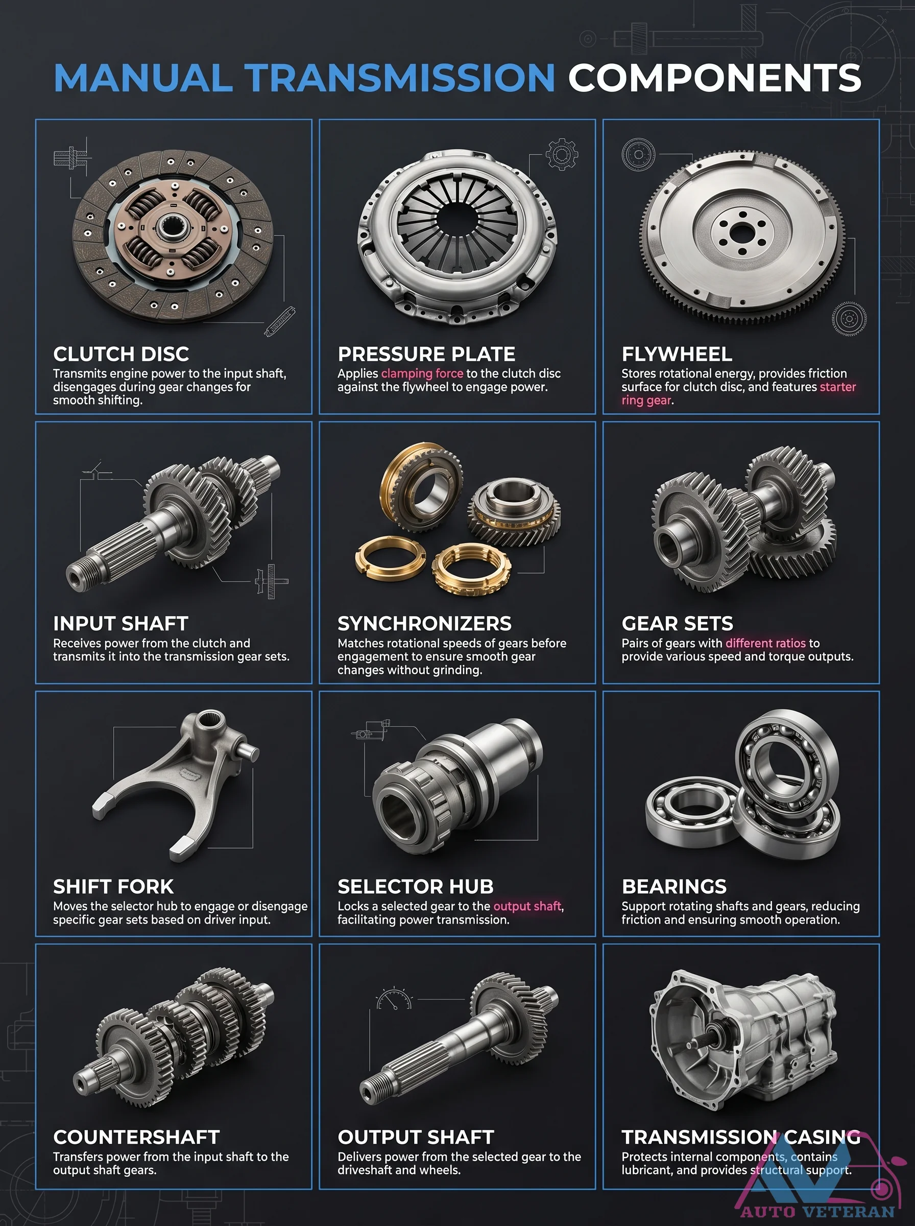
Manual Transmission Components Clutch Disc Pressure Plate Flywheel
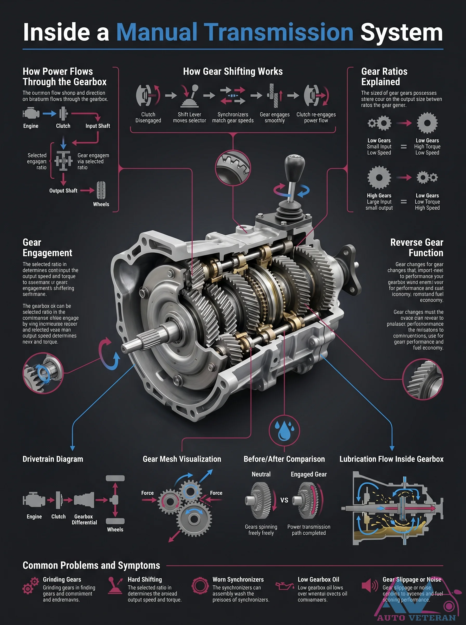
This detailed diagram breaks down the core components of a manual transmission system, starting with the clutch assembly. The flywheel stores rotational energy and provides the friction surface for the clutch disc; the pressure plate applies clamping force to engage or disengage power; and the clutch disc transmits engine power to the input shaft during gear changes. Further along the driveline, synchronizers match gear speeds for smooth shifts, gear sets provide different ratios, and the shift fork moves the selector hub to lock specific gears. The countershaft transfers power from input to output shaft, supported by bearings inside the transmission casing which protects internals and contains lubricant.
Manual Transmission Gear Ratio Flow
Explore how power flows through a manual transmission system as gear ratios determine output speed and torque. This guide visualizes the path from engine through clutch, input shaft, countershaft, and output shaft, showing how gear engagements shift torque and speed for optimal performance or fuel economy. It also covers common symptoms like grinding gears and hard shifting caused by worn synchronizers or low gearbox oil.
Mastering Manual Transmission Shifting Basics
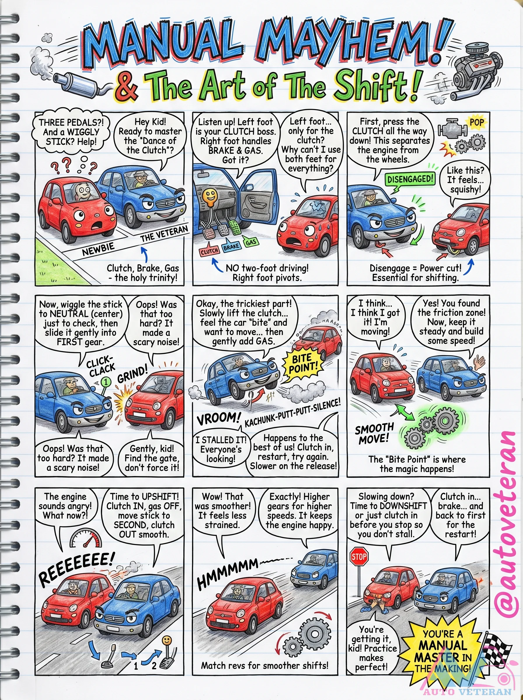
Learning to drive a manual transmission involves coordinating the clutch, brake, and gas pedals with precise gear shifts; this guide covers essential techniques like finding the friction zone, avoiding stalls, and executing smooth upshifts and downshifts for confident driving.
Mercedes C-Class Evolution Through Generations
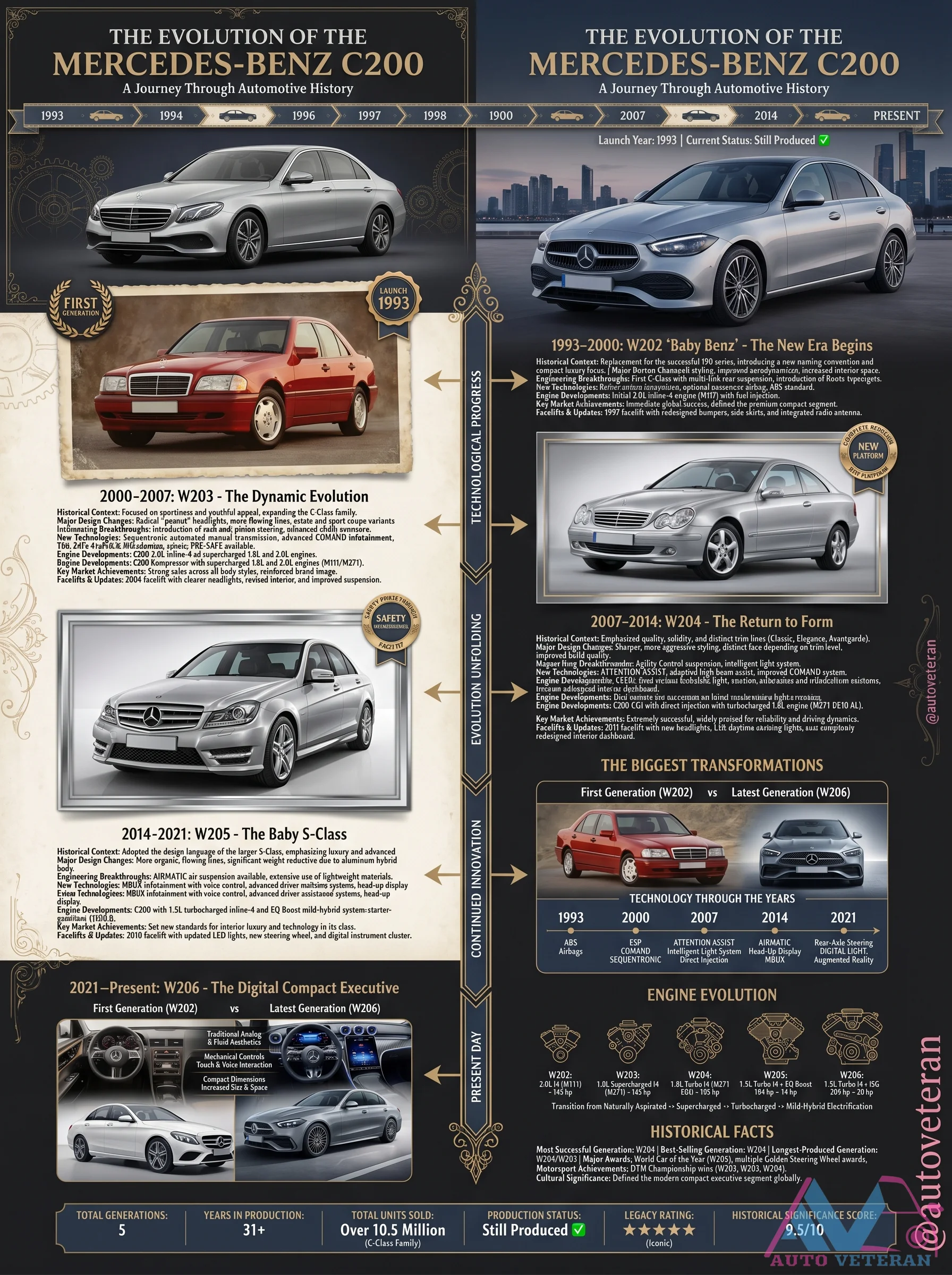
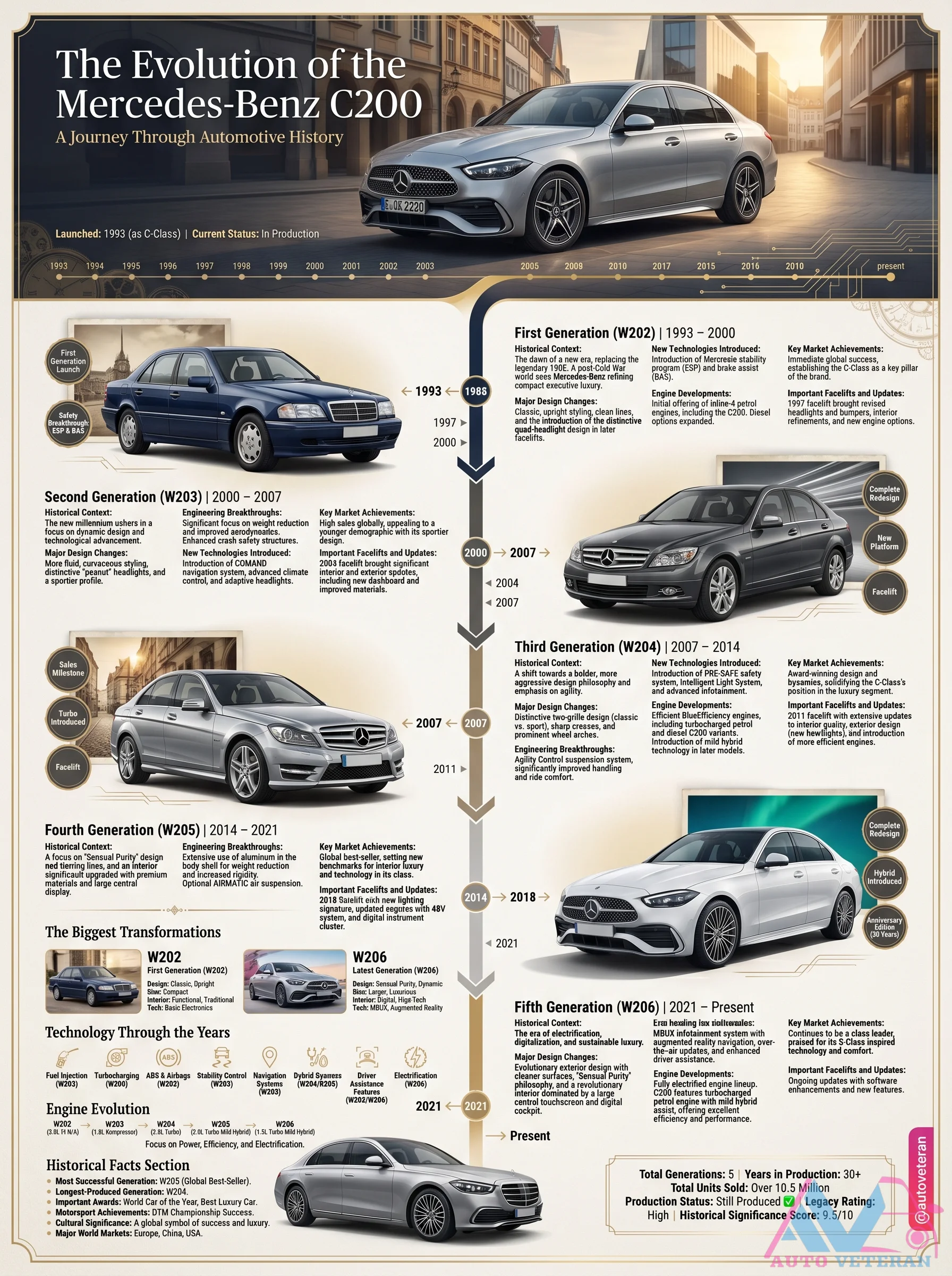
This timeline chart documents the complete journey of the Mercedes Benz C Class from its 1993 debut with the W202 Baby Benz through the W206 digital executive of 2021. Each generation is detailed with key design traits and technological shifts. The W203 brought dynamic evolution, the W204 returned to form, the W205 earned the Baby S Class nickname, and the W206 introduced the latest digital interface. Engine evolution shows progression from the M111 four cylinder to the M254 with mild hybrid tech. Over 10.5 million units have been produced, making the C Class a cultural icon in automotive history.
Mercedes C200 Generations Evolution
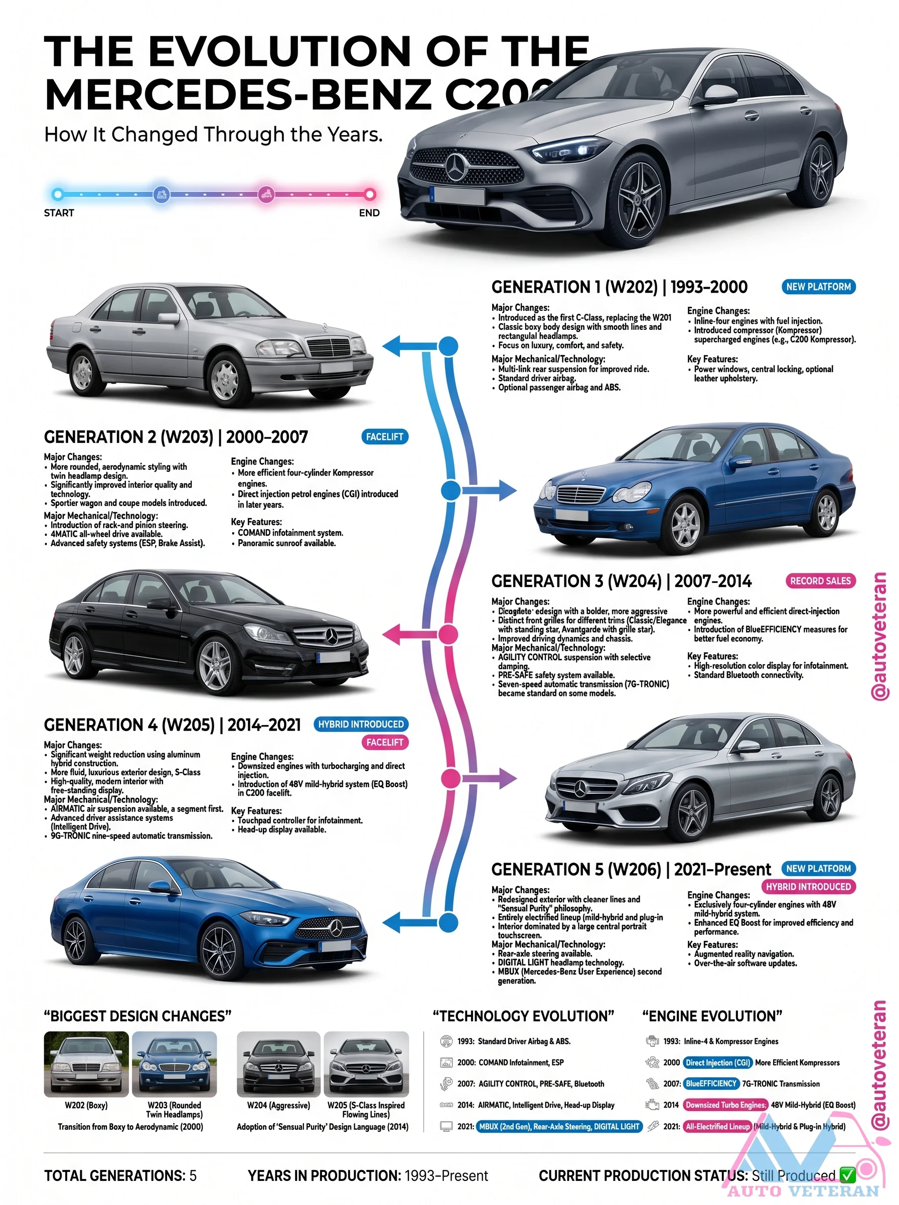
From the W202 (1993-2000) with its rounded design and fuel injection introduction, through the W203 (2000-2007) featuring Kompressor supercharged engines and ESP stability control, to the W204 (2007-2014) with CGI turbo engines and Pre-Safe safety, then the W205 (2014-2021) with MRA platform and 9G-TRONIC, and finally the W206 (2021-present) with 48V mild-hybrid systems and MBUX portrait touchscreen. This timeline covers five generations over 31+ years of the Mercedes C200.
Mercedes-Benz C-Class Generations Evolution
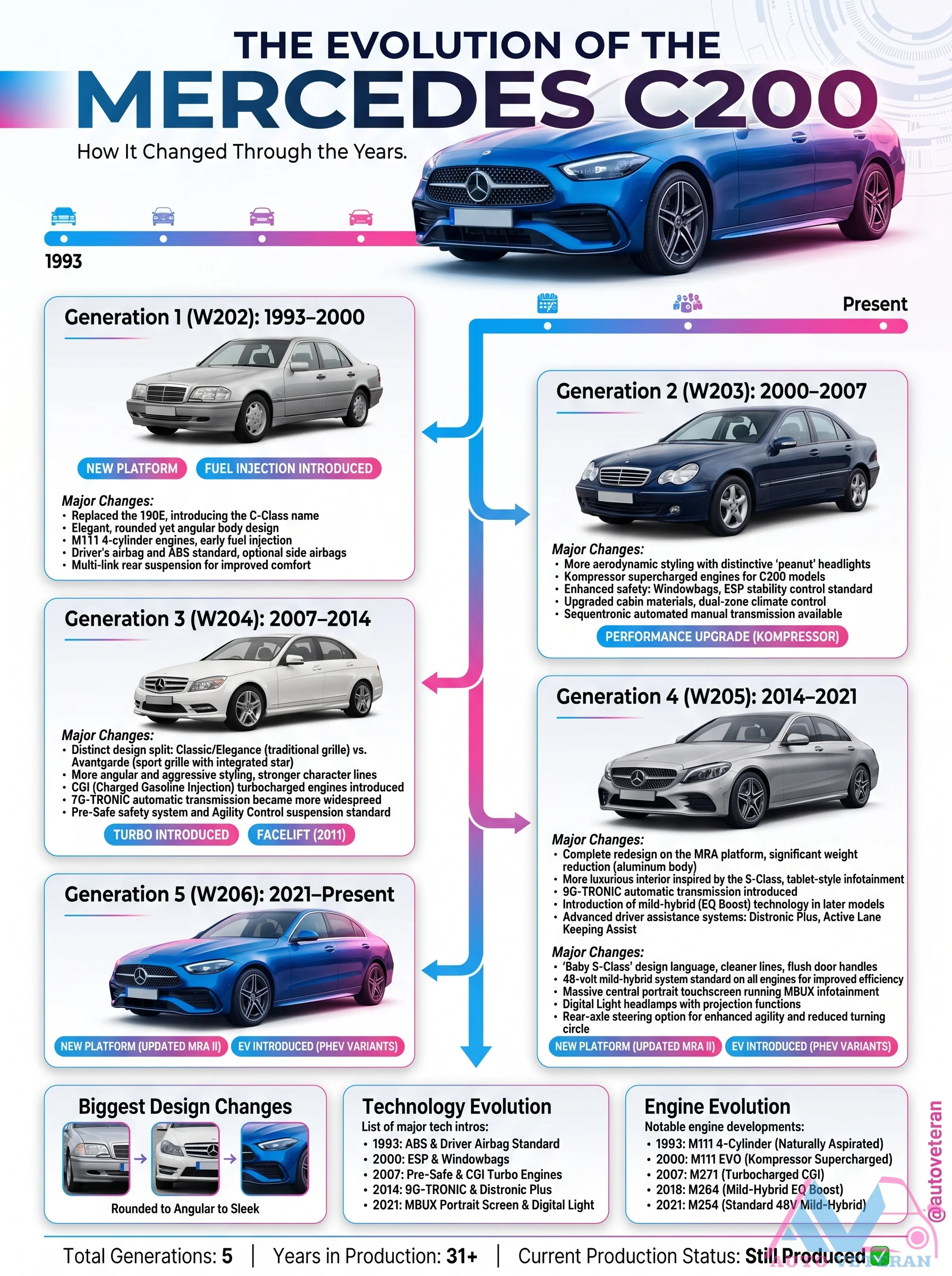
The Mercedes-Benz C-Class has evolved through five distinct generations from 1993 to the present. Starting with the W202 in 1993, it introduced a new form factor and mechanical technology. The W203 brought a facelift and engine changes with improved electrical systems. The W204 achieved record sales with efficient engines and advanced safety features like Brake Assist. The W205 introduced a new platform with turbocharging, direct injection, and 48V mild hybrid technology. The current W206 debuts a fresh design and enhanced infotainment. Each generation brought key design changes, technology evolution, and engine advancements.
Mercedes-Benz C200 Generations Evolution
From the first generation W202 launched in 1993 to the current W206 series, the Mercedes-Benz C200 has undergone a remarkable transformation over nearly three decades. Each generation brought unique design language, technological advancements, and powertrain refinements. The W203 introduced supercharged engines and improved safety, while the W204 offered a more luxurious interior and efficient diesel options. The W205 marked the shift to lightweight aluminum construction and turbocharged four cylinder engines. The latest W206 combines electrified powertrains with cutting edge MBUX infotainment. With over 10.5 million units sold and production still ongoing, the C200 remains a benchmark in the compact executive sedan segment.
Modern Automotive Technologies Overview
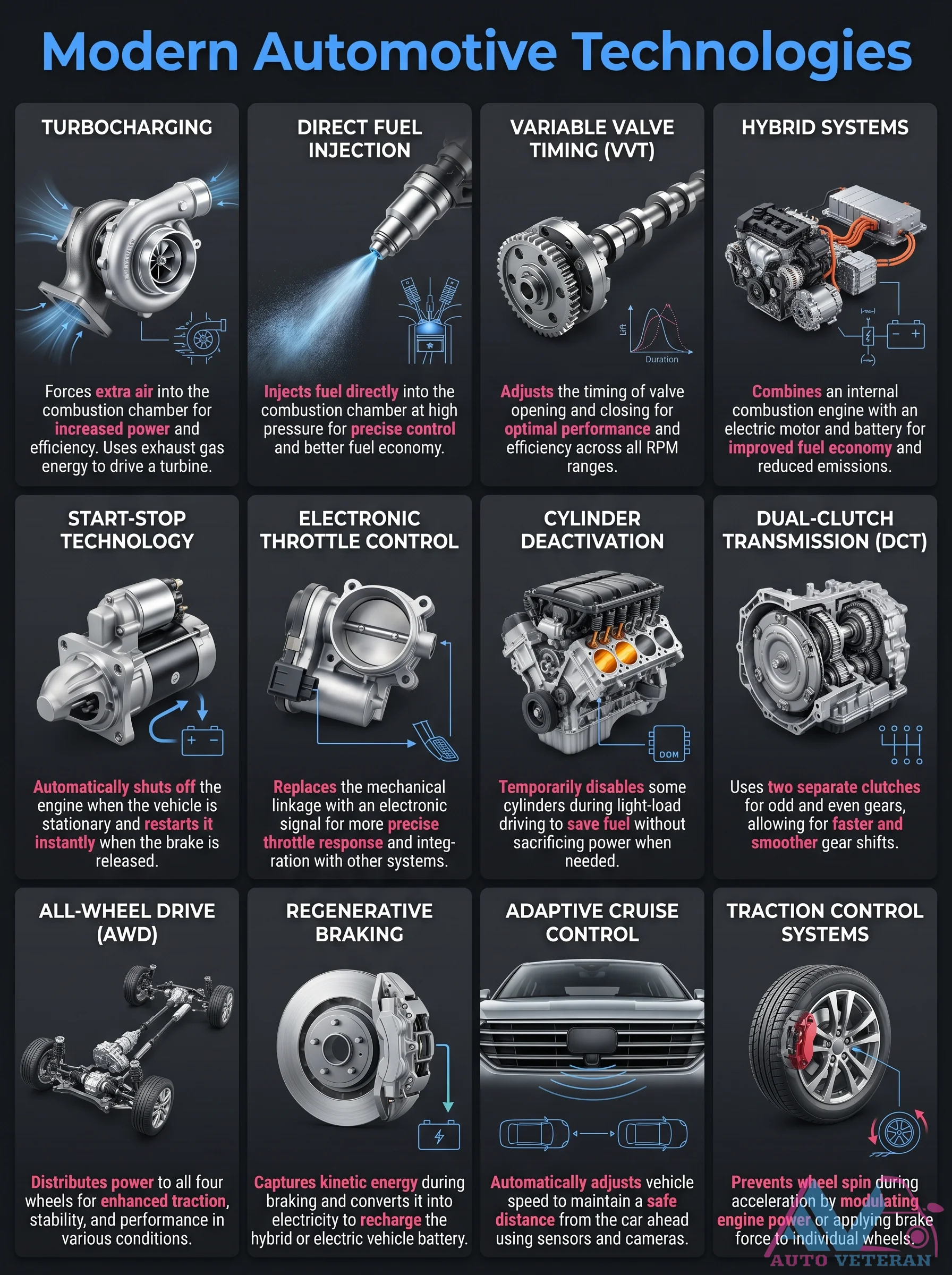
This chart presents a comprehensive overview of cutting edge automotive technologies including turbocharging which forces extra air into the combustion chamber for increased power; direct fuel injection which injects fuel at high pressure for precise control and better fuel economy; variable valve timing which adjusts valve opening for optimal performance across all RPM ranges; hybrid systems that combine an internal combustion engine with an electric motor and battery for improved fuel economy and reduced emissions; start-stop technology that automatically shuts off the engine when the vehicle is stationary and restarts it instantly; electronic throttle control which replaces mechanical linkage with an electronic signal for more precise throttle response; cylinder deactivation that temporarily disables some cylinders during light load driving to save fuel; dual clutch transmission using two separate clutches for odd and even gears enabling faster and smoother gear shifts; all wheel drive distributing power to all four wheels for enhanced traction and stability; regenerative braking capturing kinetic energy and converting it into electricity to recharge the battery in hybrid or electric vehicles; adaptive cruise control automatically adjusting vehicle speed to maintain a safe distance from the car ahead using sensors and cameras; and traction control preventing wheel spin during acceleration by applying brake force to individual wheels.
Modern Coil-on-Plug Ignition System Components
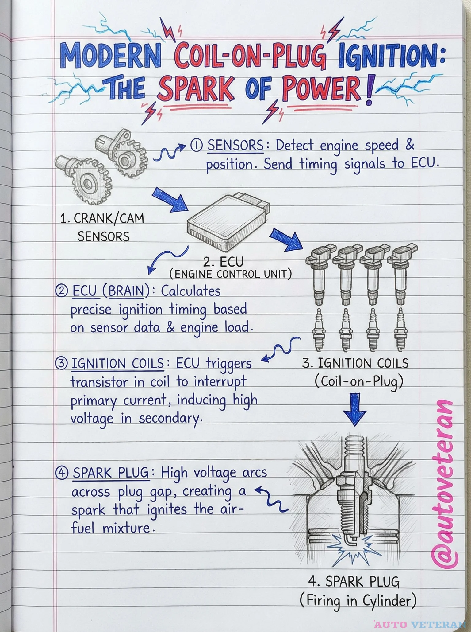
The modern coil-on-plug ignition system represents a sophisticated integration of sensors, electronic control, and high voltage components working in precise harmony. Crank and cam sensors continuously monitor engine speed and position, sending real time data to the Engine Control Unit. This electronic brain processes sensor inputs alongside engine load parameters to calculate optimal ignition timing with millisecond precision. The ECU then triggers transistors within individual ignition coils, interrupting primary current flow to induce high voltage in the secondary windings. This electrical surge travels directly to the spark plug, where it arcs across the electrode gap, creating the controlled explosion that ignites the air fuel mixture within each cylinder. This direct firing approach eliminates traditional distributor systems, providing more accurate spark timing, improved combustion efficiency, and enhanced engine performance across all operating conditions.