Interactive Explorer

Famous Car Logos Origins
Discover the fascinating stories behind iconic automotive emblems. From Cadillac's coat of arms to the Citroen double chevron inspired by a freemason, and from Hyundai's nod to modernity to Toyota's shift to lucky strokes. Each logo carries a hidden history.

Fastest Production Cars of the Last Decade
The Koenigsegg Jesko Absolut dominates the list with a top speed of 310 mph, followed by the Bugatti Chiron Super Sport 300+ at 304 mph and the SSC Tuatara reaching up to 295 mph, showcasing the relentless pursuit of speed in automotive engineering.

Fastest Production Cars Top Speed Comparison 2025-2024
The YangWang Ug Xtreme leads the 2025 rankings with a blistering 308.4 mph, while the SSC Tuatara dominates 2024 at 295 mph. This data reveals the relentless pursuit of speed in modern hypercars, showcasing how manufacturers push aerodynamic limits and powertrain technology to achieve these extraordinary velocities.

First Cars of Iconic Automotive Brands
This image showcases the pioneering first production cars from automotive giants like Ford's Model T, Toyota's Model AA, Honda's S500, and BMW's Dixi. From the mass production revolution to the dawn of affordable mobility and high performance EVs, each vehicle laid the foundation for its brand's legacy in engineering and innovation.
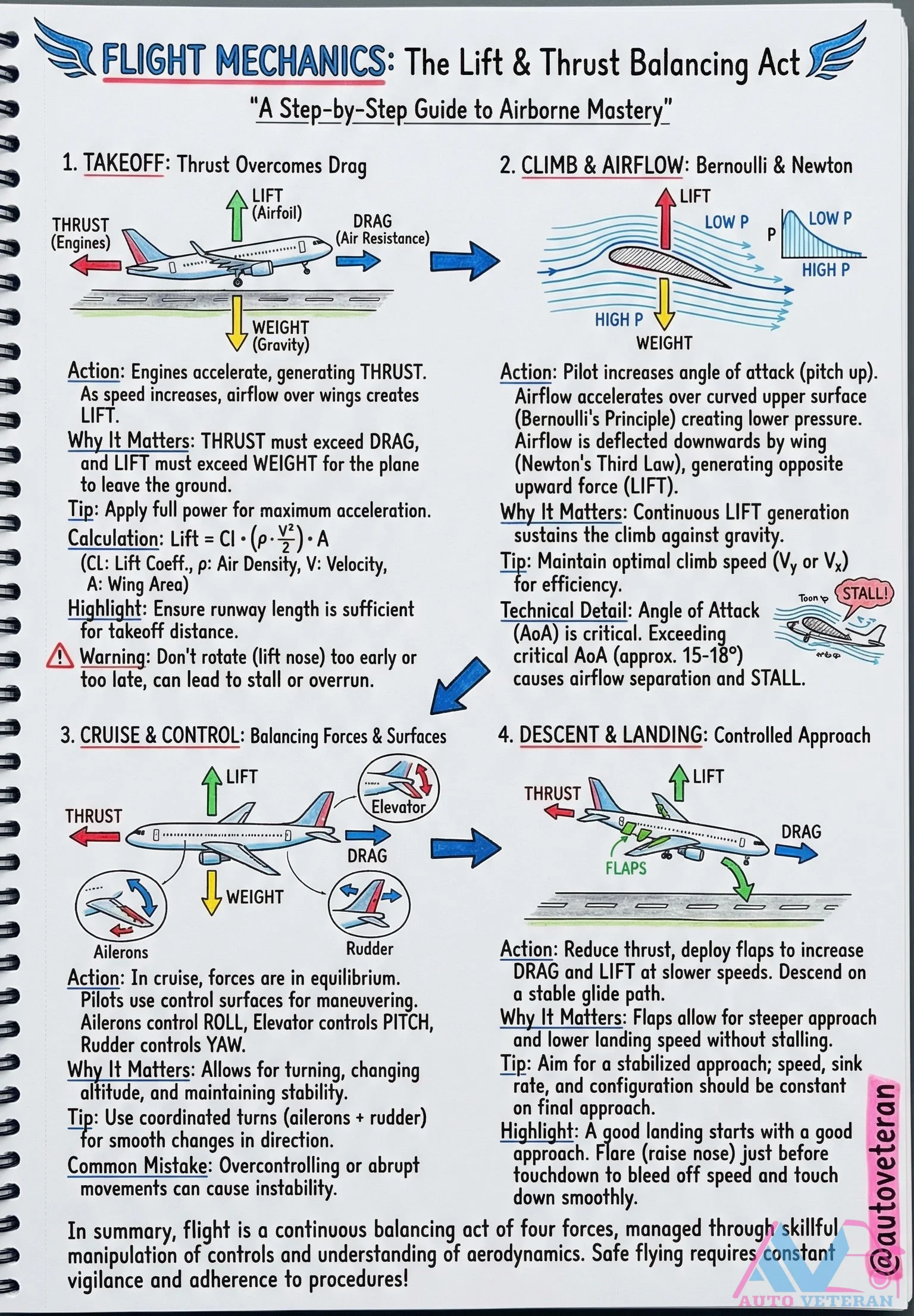
Flight Mechanics Lift and Thrust Balancing Step-by-Step Guide
Master the fundamental principles of flight mechanics through a detailed step-by-step guide that explains how lift and thrust work together to achieve airborne mastery. The process begins with takeoff, where thrust must overcome drag to accelerate the aircraft, and pilots must apply full power for maximum acceleration while ensuring sufficient runway length. During climb, airflow over wings creates lift through Bernoulli's Principle and Newton's Third Law, with the critical angle of attack approximately 15 to 18 degrees; exceeding this causes airflow separation and stall. In cruise, forces reach equilibrium as pilots use ailerons for roll, elevator for pitch, and rudder for yaw, allowing coordinated turns for directional changes. The descent and landing phase involves reducing thrust, deploying flaps to increase drag and lift at slower speeds, aiming for a stabilized approach with constant sink rate and configuration. This continuous balancing act of four forces, managed through aerodynamic understanding and control manipulation, ensures safe and efficient flight operations.
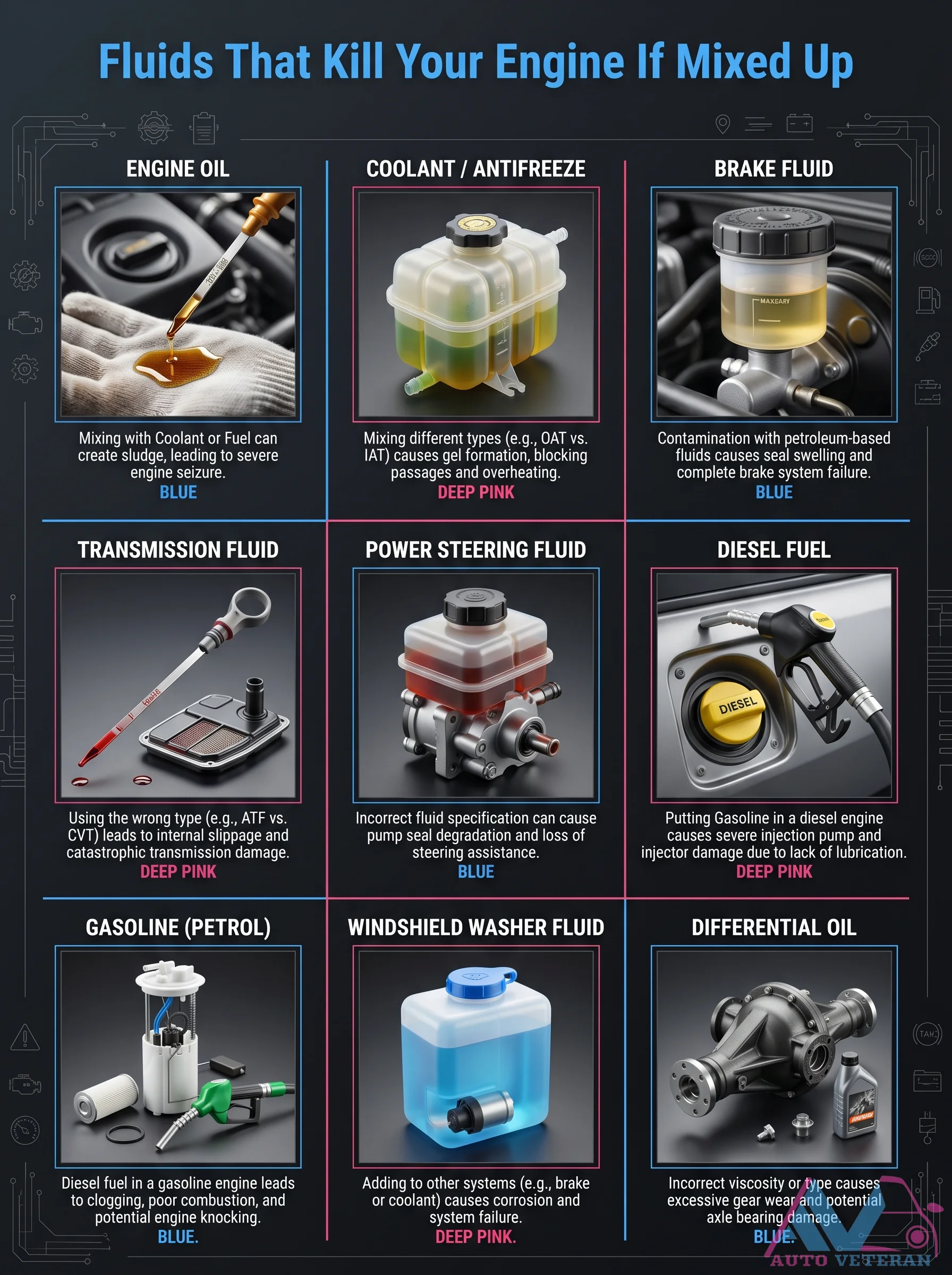
Fluid Mixing Dangers That Can Kill Your Engine
Mixing incompatible automotive fluids leads to catastrophic failures across multiple systems. Engine oil contaminated with coolant creates sludge that causes severe engine seizure. Using the wrong transmission fluid type results in internal slippage and catastrophic transmission damage. Diesel fuel in gasoline engines causes poor combustion and potential knocking, while gasoline in diesel engines destroys injection pumps and injectors due to lack of lubrication. Brake fluid contaminated with petroleum based fluids causes seal swelling and complete brake system failure. Power steering fluid with incorrect specifications leads to pump seal degradation and loss of steering assistance. Differential oil with wrong viscosity causes excessive gear wear and axle bearing damage. Windshield washer fluid added to other systems creates corrosion and system failure.
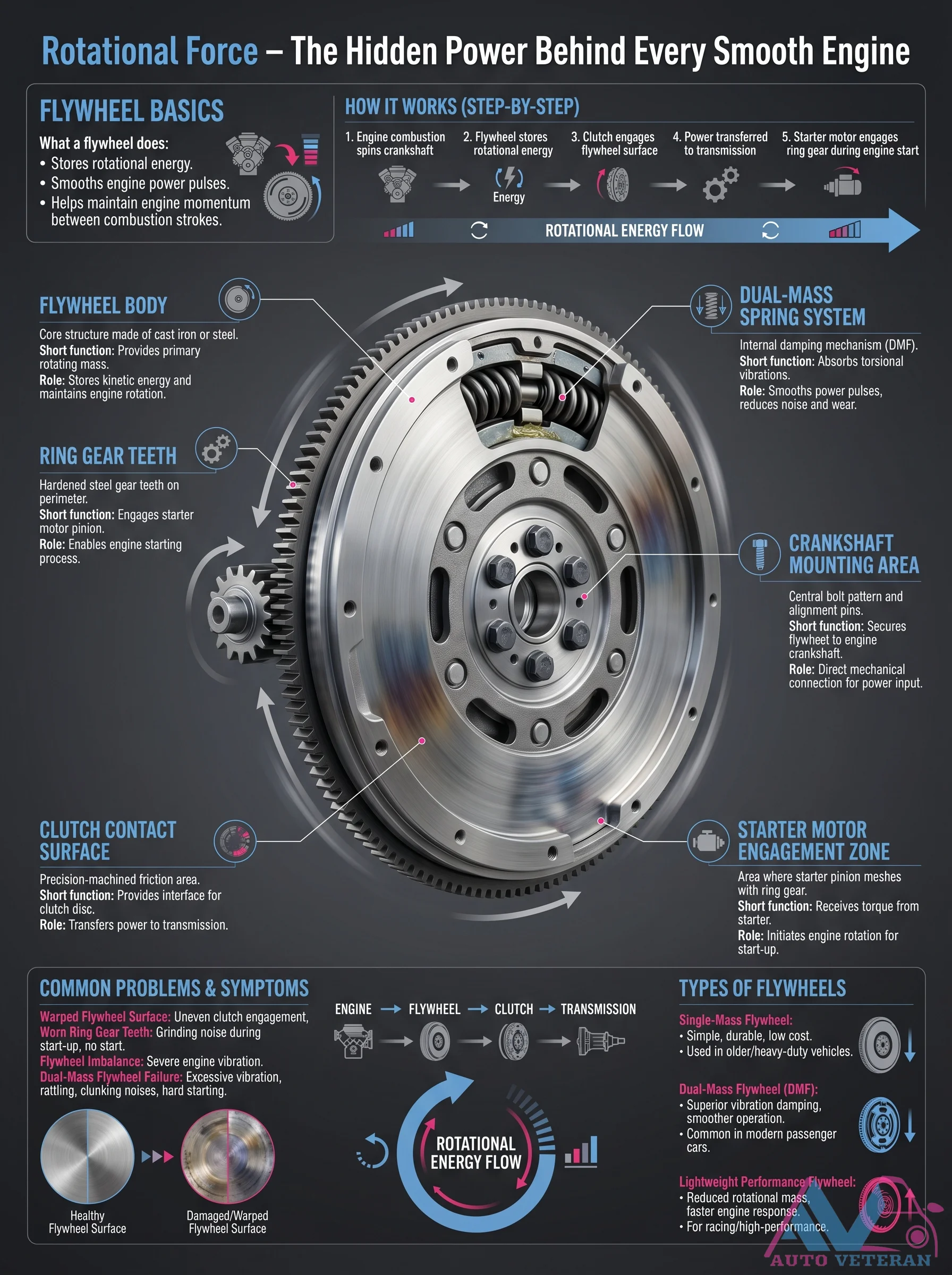
Flywheel Basics and Rotational Energy Flow
The flywheel stores rotational energy from combustion strokes, smoothing power pulses and maintaining engine momentum between firings. This guide breaks down the step by step function of a single mass flywheel versus a dual mass flywheel (DMF), explains how the ring gear teeth engage the starter motor pinion to initiate engine rotation, and details the clutch contact surface that transfers torque to the transmission. Common problems such as a warped flywheel surface causing uneven clutch engagement, worn ring gear teeth producing grinding noise at startup, flywheel imbalance leading to severe vibration, and DMF failure resulting in excessive vibration, rattling, or clunking noises are covered.
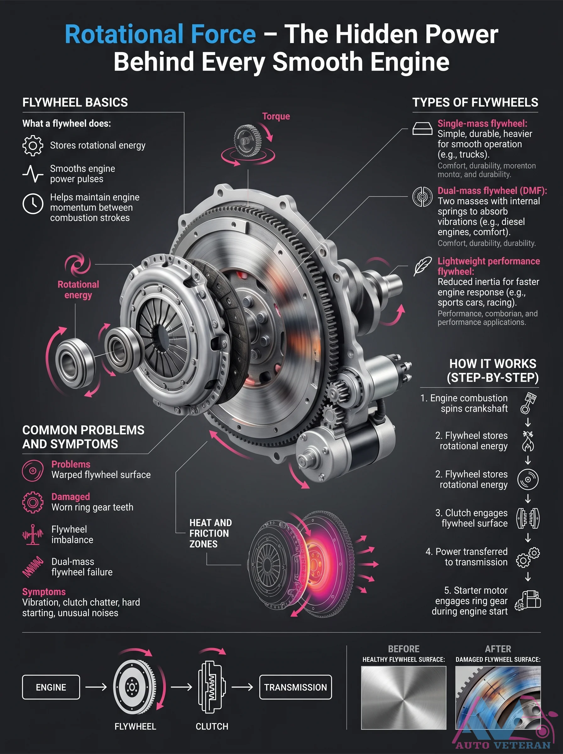
Flywheel Types and Failure Symptoms
A flywheel stores rotational energy to smooth out engine power pulses, but different types suit different needs. Single mass flywheels are simple and durable yet heavy, delivering raw durability for trucks. Dual mass flywheels use two masses with internal springs to absorb vibrations, making them ideal for diesel engines and comfort focused vehicles. Lightweight performance flywheels reduce inertia for faster engine response in sports cars and racing. Common problems include a warped surface, worn ring gear teeth, imbalance, and dual mass flywheel failure. Symptoms include vibration, clutch chatter, hard starting, and unusual noises during engine start. The flywheel sits between the engine and transmission, transferring power via the clutch.

Ford Mustang Complete Vehicle Overview
This authoritative overview covers the Ford Mustang from 1964 to present, detailing quick facts like dimensions of 188.5 inches in length and 75.4 inches in width, engine options including the 2.3L EcoBoost inline 4 with 315 horsepower and the 5.0L Coyote V8 producing 480 to 500 horsepower, and the high performance 5.2L Predator V8 in the Shelby GT500 generating 760 horsepower. The overview highlights transmission choices such as the 6 speed MT 82 manual, 10 speed SelectShift automatic, and the 7 speed Tremec dual clutch for Shelby models. Performance figures note a top speed of up to 180 mph and 0 to 60 mph in about 4.3 seconds for the GT. With generations spanning from 1964 to 1973 up to 2024 and beyond, common problems include transmission issues with the MT 82, EcoBoost head gasket problems, and paint quality concerns. Strengths emphasize iconic design, powerful V8 options, and engaging dynamics. Safety features comprise multiple airbags, 4 wheel ABS, AdvanceTrac stability control, and Ford Co Pilot360 with Pre Collision Assist and Lane Keeping. Market information lists competitors like Chevrolet Camaro and Dodge Challenger, with best model years including 2011 to 2014 and 2018 and newer. The overall reliability score is 8 out of 10, and production status is still ongoing.
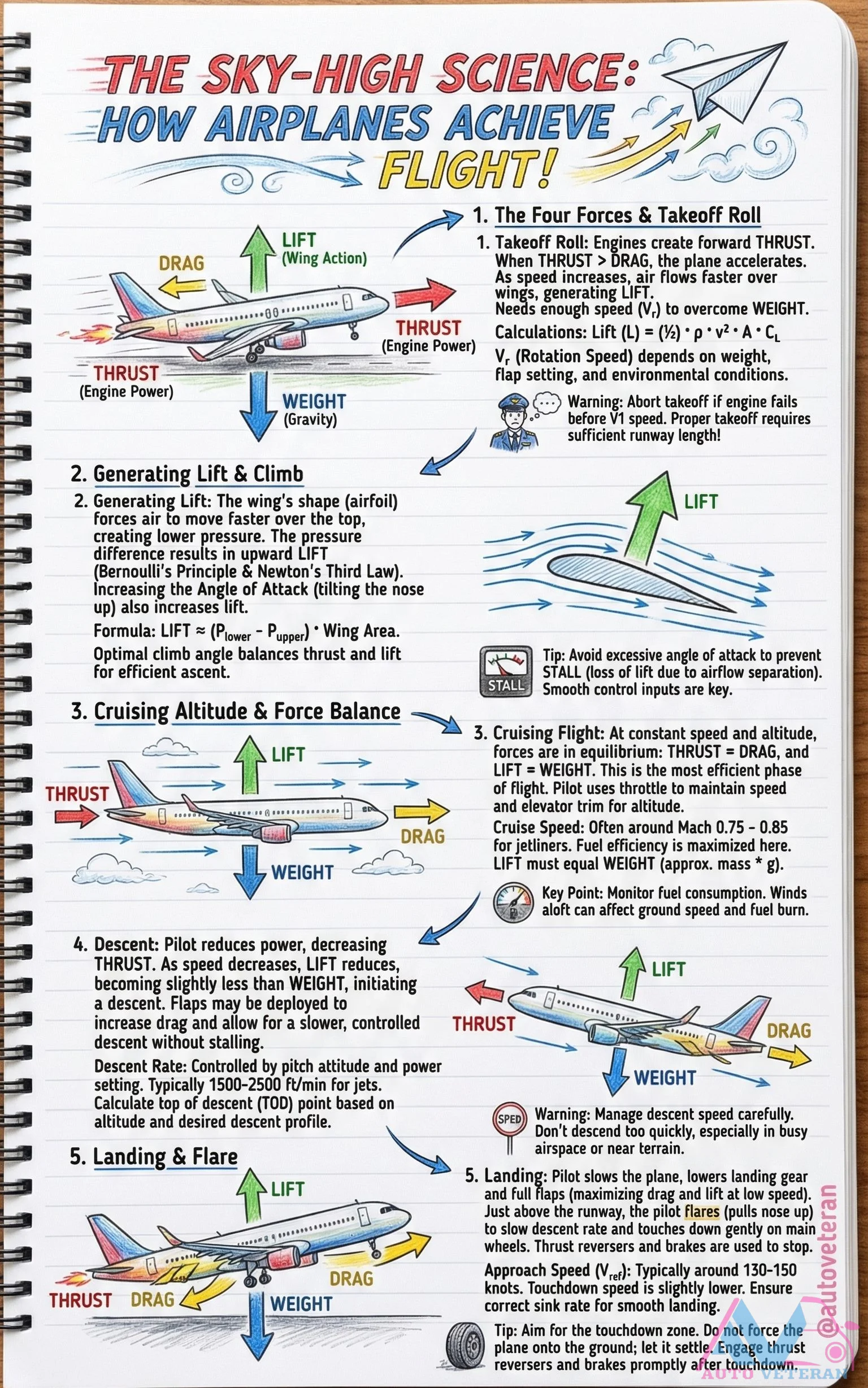
Four Forces of Flight and Takeoff to Landing Sequence
The fundamental physics of aviation revolves around the delicate balance between lift, weight, thrust, and drag. During takeoff, engines generate forward thrust to accelerate the aircraft until reaching rotation speed (V1), where sufficient lift overcomes weight. The wing's airfoil shape creates pressure differentials through Bernoulli's principle, generating upward force. In cruising flight, lift equals weight while thrust balances drag at optimal speeds around Mach 0.75 to 0.85 for maximum fuel efficiency. Descent is initiated by reducing power, making lift slightly less than weight, with controlled descent rates of 500 to 2500 feet per minute. The landing sequence involves slowing to approach speeds of 130 to 150 knots, deploying flaps and landing gear for maximum lift at low speeds, executing a flare maneuver just above the runway, and using thrust reversers and brakes after touchdown. Proper management of angle of attack prevents stalls, while smooth control inputs ensure efficient transitions between flight phases.
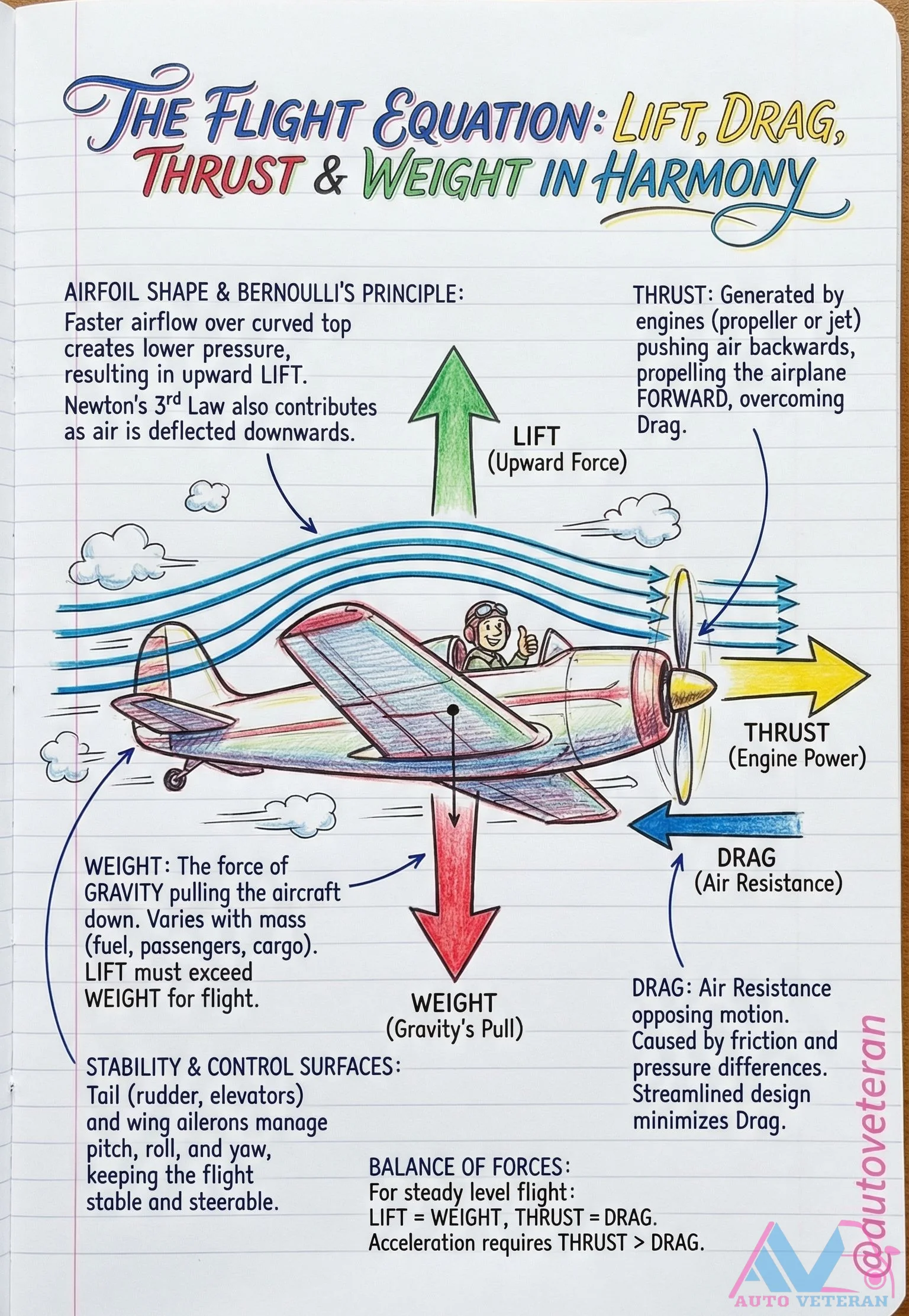
Four Forces of Flight and Their Equilibrium
This diagram illustrates the fundamental physics of aircraft flight, where lift, weight, thrust, and drag must achieve precise balance. Lift, generated by airfoil shape and Bernoulli's principle through faster airflow over curved surfaces, must exceed weight for takeoff. Thrust from engines overcomes drag from air resistance, while stability is maintained by control surfaces like ailerons and rudders. For steady level flight, lift equals weight and thrust equals drag, with acceleration requiring thrust to surpass drag.
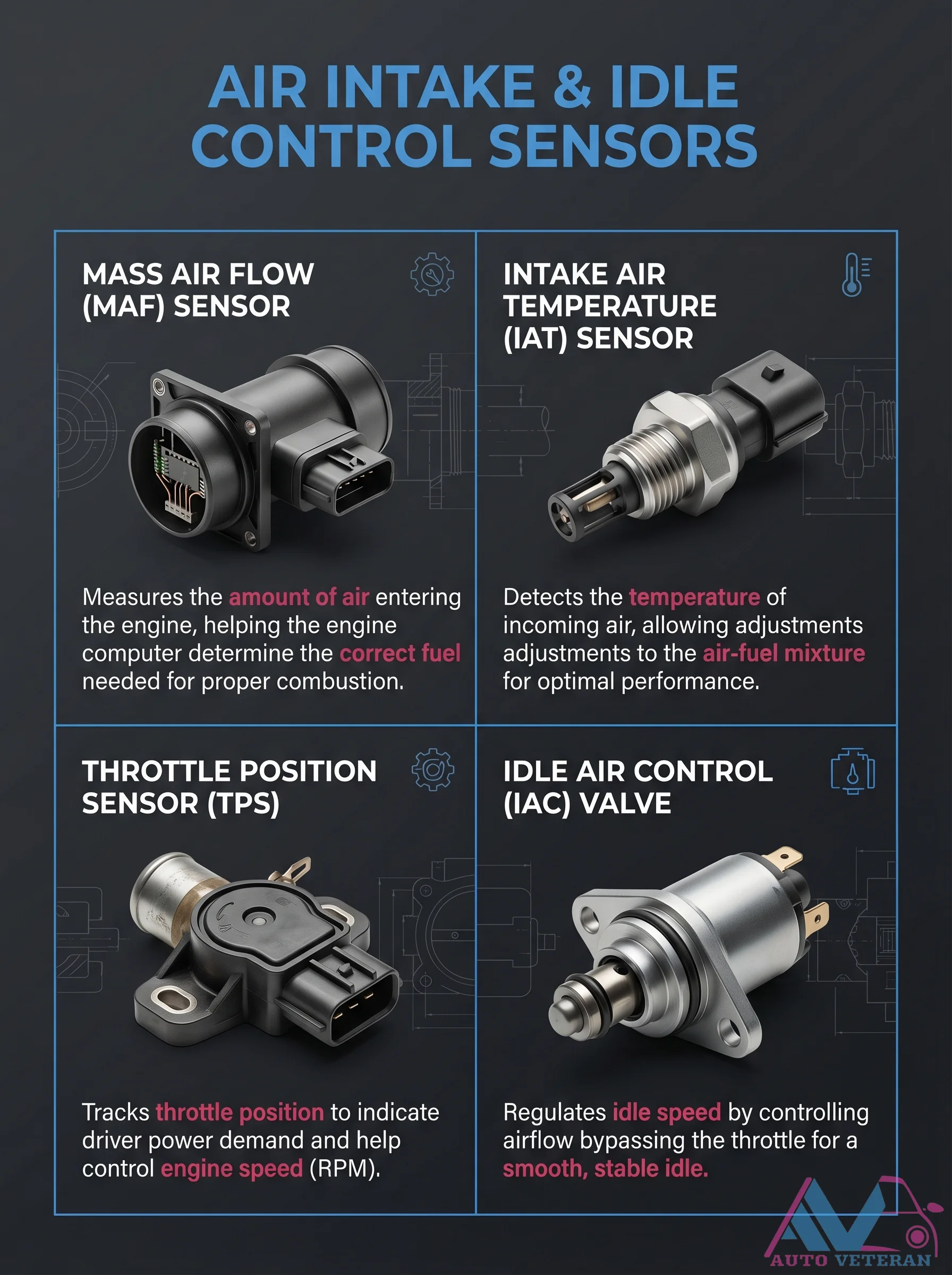
Four Key Air Intake and Idle Control Sensors
This diagram illustrates the four essential sensors that manage air intake and idle control in modern engines: the Mass Air Flow sensor measures incoming air volume for precise fuel calculation, the Intake Air Temperature sensor detects air temperature for mixture adjustments, the Throttle Position Sensor tracks throttle opening to indicate driver demand, and the Idle Air Control Valve regulates bypass airflow to maintain smooth, stable idle speed. Together, these components ensure optimal combustion, performance, and engine responsiveness.
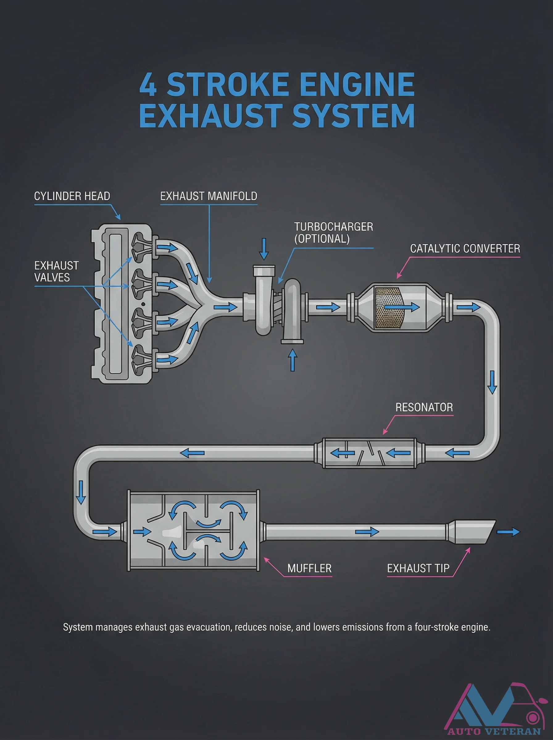
Four-Stroke Engine Exhaust System Components
The exhaust system in a four-stroke engine is a critical assembly designed to efficiently evacuate combustion gases, reduce operational noise, and minimize harmful emissions. Key components include the cylinder head, exhaust valves, exhaust manifold, optional turbocharger, catalytic converter, resonator, muffler, and exhaust tip. This integrated system ensures optimal engine performance while meeting environmental standards.

Frequent Coolant Top-Up Warning Signs
Repeatedly adding coolant to your vehicle is not normal maintenance; it signals underlying system issues like leaks, pressure loss, or internal engine faults. Ignoring this habit leads to progressive overheating, cylinder head warping, coolant-oil contamination, and eventual engine seizure. Watch for subtle warning signals including temperature instability, sweet smells in the engine bay, moisture accumulation at connection points, and micro leaks that escape casual inspection.
Fuel Injector Nozzle System Basics and Injection Process
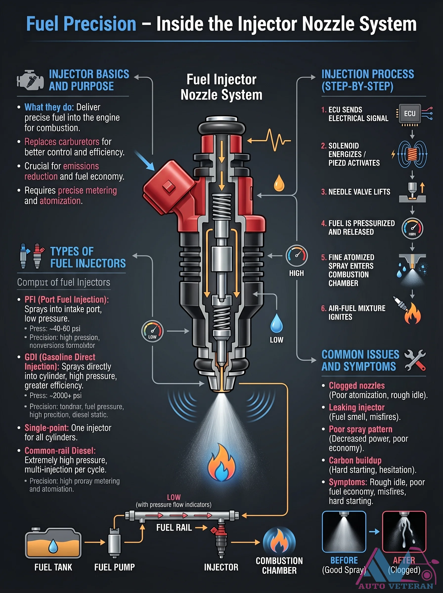
The fuel injector nozzle system delivers precise fuel into the engine for combustion, replacing carburetors for better control and efficiency. This system is crucial for emissions reduction and fuel economy, requiring exact metering and atomization. The injection process begins when the ECU sends an electrical signal, energizing the solenoid or piezo actuator, which lifts the needle valve to release pressurized fuel as a fine atomized spray into the combustion chamber. Types include PFI with 40-60 psi pressure and GDI with over 2000 psi pressure, each offering different precision levels. Common issues involve clogged nozzles causing poor atomization and rough idle, leaking injectors leading to fuel smell and misfires, or poor spray patterns resulting in decreased power and economy. Symptoms like rough idle, poor fuel economy, misfires, and hard starting indicate potential injector problems.
Fuel Injector Nozzle System Step-by-Step Process
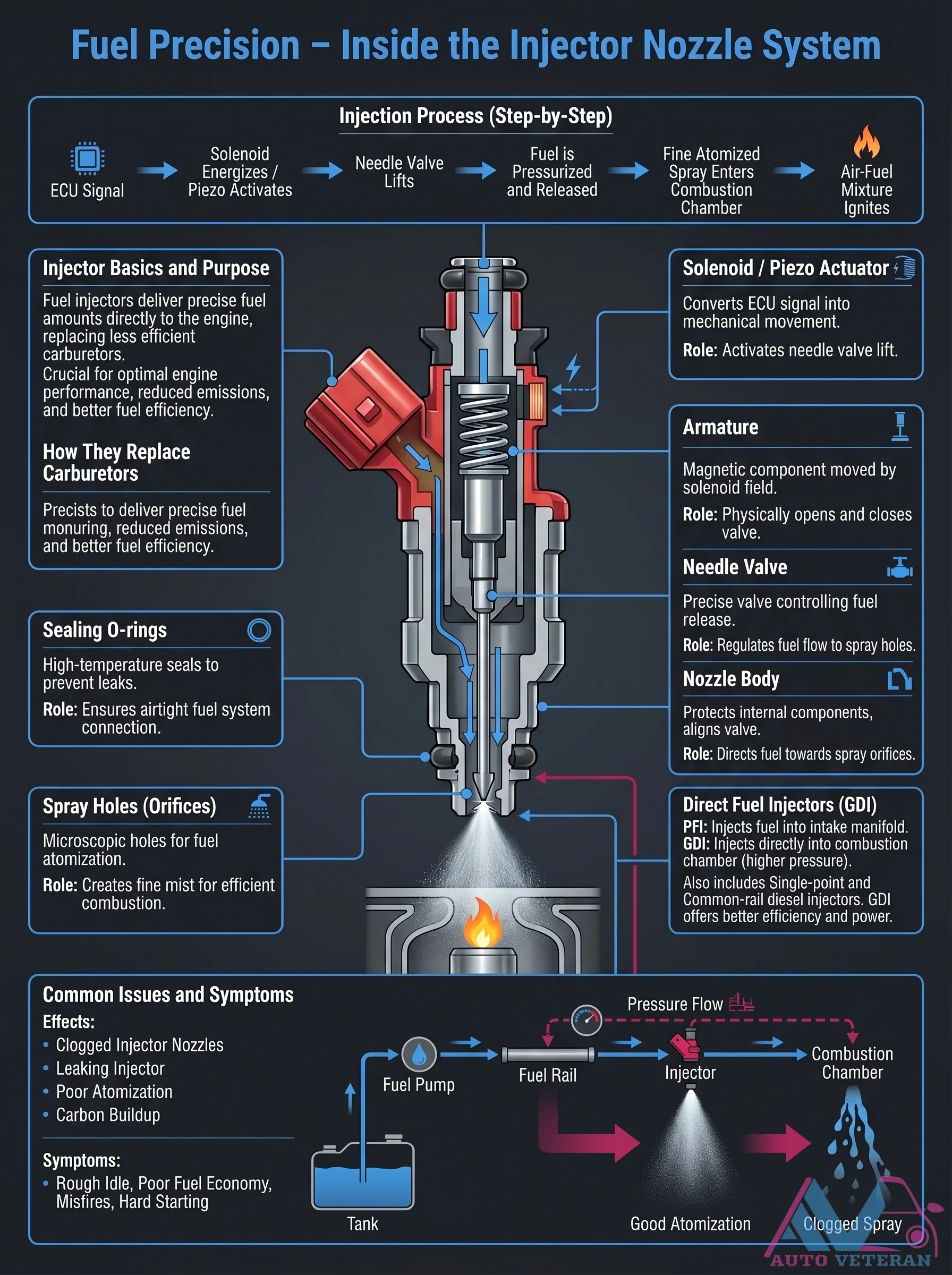
The fuel injection process begins when the ECU sends a signal to the solenoid or piezo actuator, which converts electrical energy into mechanical movement to lift the needle valve. Pressurized fuel then flows through the nozzle body and is atomized into a fine mist through microscopic spray holes before entering the combustion chamber for efficient ignition. This precise system replaces older carburetors by delivering exact fuel amounts, optimizing engine performance, reducing emissions, and improving fuel economy. Common issues include clogged nozzles or leaking injectors, which can cause symptoms like rough idle, misfires, or poor acceleration.
Fuel Injector Solenoid Operation and Atomization
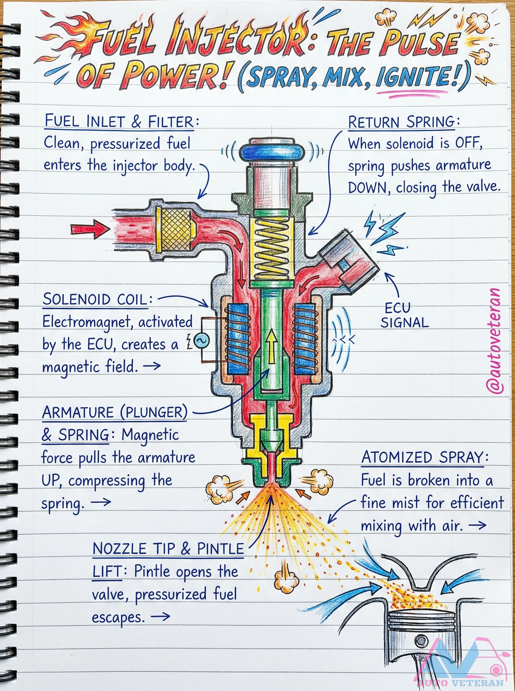
The solenoid coil in a fuel injector acts as an electromagnet, activated by the ECU signal to create a magnetic field that pulls the armature upward against spring pressure. This lifts the pintle valve, allowing pressurized fuel to escape through the nozzle tip where it's atomized into a fine mist for efficient mixing with air. When the solenoid deactivates, the return spring pushes the armature down, closing the valve and stopping fuel flow.
FWD System Transverse Engine Diagram
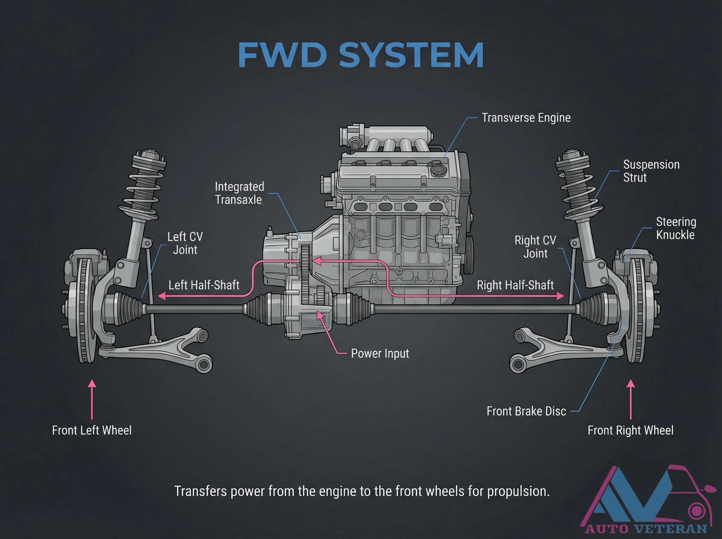
This diagram illustrates the key components of a Front Wheel Drive system with a transverse engine layout, including the integrated transaxle, CV joints, half shafts, and suspension struts that work together to transfer power from the engine to the front wheels for propulsion.