Interactive Explorer
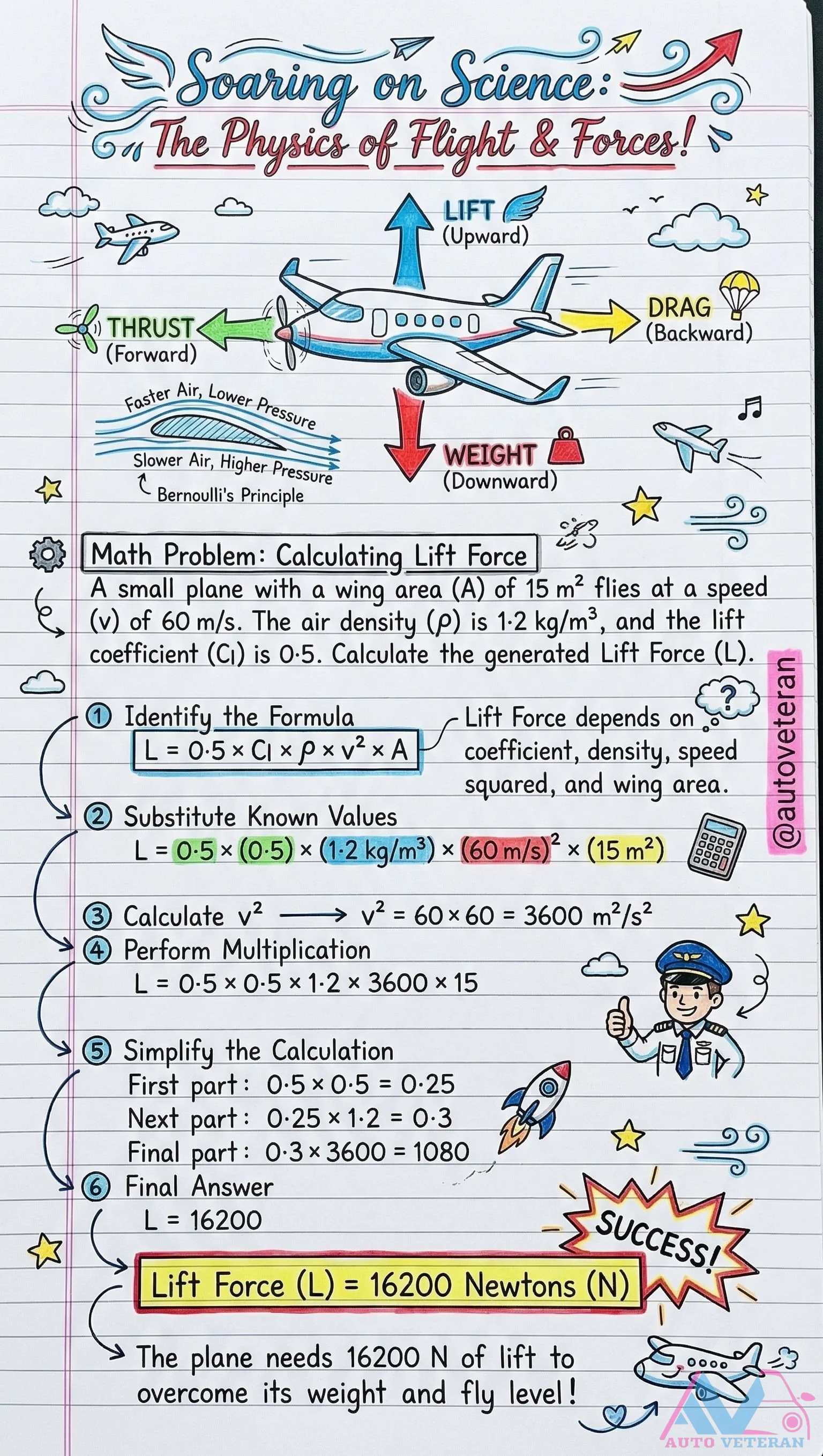
Calculating Lift Force Using Bernoulli's Principle
This detailed example demonstrates how to calculate the lift force generated by an airplane wing using Bernoulli's principle and the standard lift equation. With a wing area of 15 square meters, airspeed of 60 meters per second, air density of 1.2 kilograms per cubic meter, and a lift coefficient of 0.5, the step by step calculation shows how to substitute these values into the formula L = 0.5 × Cₗ × ρ × v² × A. The calculation proceeds through squaring the velocity to 3600 square meters per second squared, then multiplying through the coefficients to arrive at a final lift force of 16,200 Newtons, which represents the upward force needed to overcome the aircraft's weight and maintain level flight.

Car Body Types Diagram and Definitions
This comprehensive diagram illustrates the key differences between common automotive body styles, including sedans with their traditional four-door layout and separate trunk compartment, hatchbacks featuring the practical rear door that opens upward for cargo access, and station wagons that extend the roof line for maximum storage capacity. The visual guide also covers SUVs designed for versatile on-road and off-road capability, crossovers that blend SUV aesthetics with car-like handling, coupes emphasizing sporty two-door designs, convertibles with retractable roofs for open-air driving, pickup trucks with enclosed cabs and open cargo beds, and minivans optimized for passenger comfort and interior space.
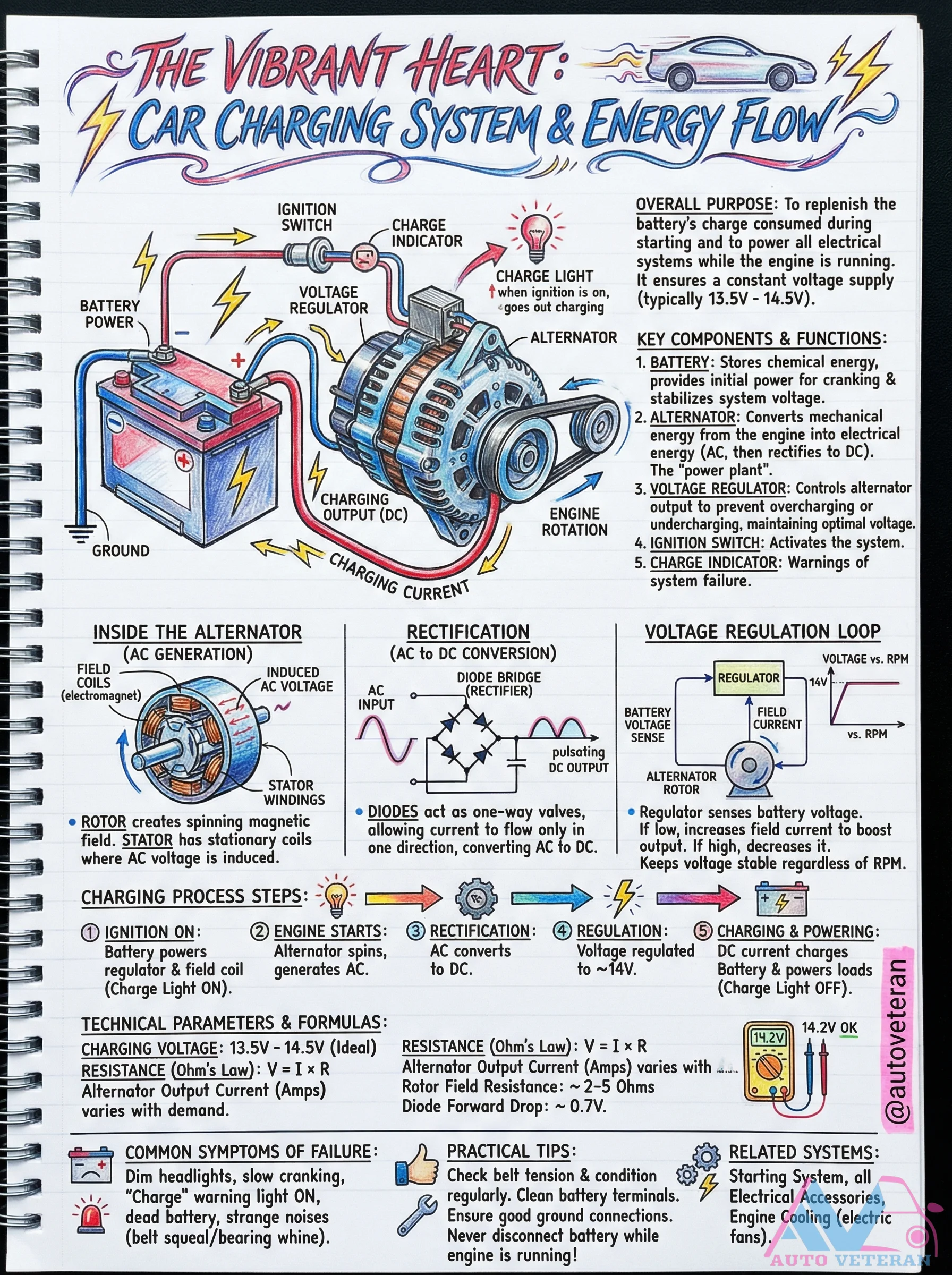
Car Charging System Energy Flow and Components
The automotive charging system functions as the vehicle's vibrant heart, replenishing battery charge consumed during starting and powering all electrical systems while the engine runs. Key components include the battery storing chemical energy for initial cranking, the alternator converting mechanical energy to electrical energy through AC generation and DC rectification, and the voltage regulator maintaining optimal 13.5V to 14.5V output. The process involves ignition activation, alternator spinning to generate AC current, rectification through diode bridges converting AC to DC, and regulation ensuring stable voltage regardless of RPM. Technical parameters include rotor field resistance of 2-5 ohms, diode forward voltage of 0.7V, and output current varying with electrical demand. Common failure symptoms manifest as dim headlights, slow cranking, warning lights, or unusual noises, while maintenance requires checking belt tension, cleaning battery terminals, and ensuring proper ground connections.
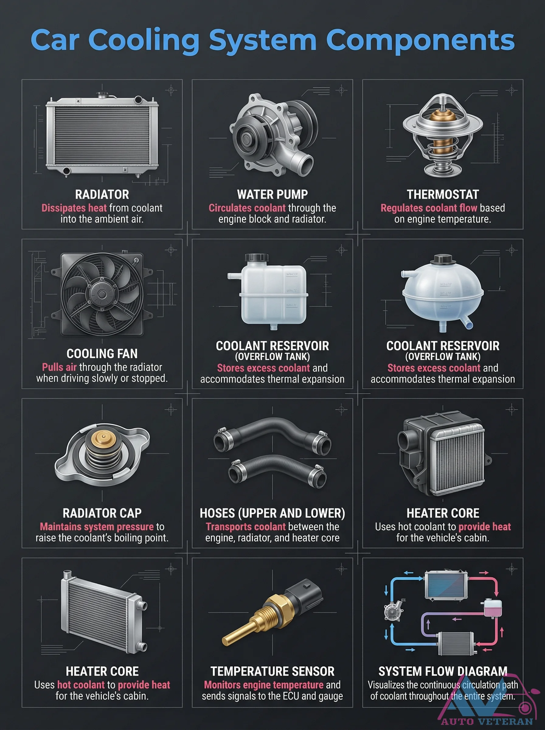
Car Cooling System Components and Flow Diagram
A comprehensive diagram illustrating all essential components of an automotive cooling system, including the radiator that dissipates heat from coolant into ambient air, the water pump that circulates coolant through the engine block and radiator, and the thermostat that regulates coolant flow based on engine temperature. The diagram also shows the coolant reservoir for storing excess fluid and accommodating thermal expansion, the cooling fan that pulls air through the radiator during low-speed driving or stops, the radiator cap that maintains system pressure to raise the coolant's boiling point, upper and lower hoses that transport coolant between components, the heater core that uses hot coolant to provide cabin heat, and the temperature sensor that monitors engine conditions. A system flow diagram visualizes the continuous circulation path of coolant throughout the entire vehicle.
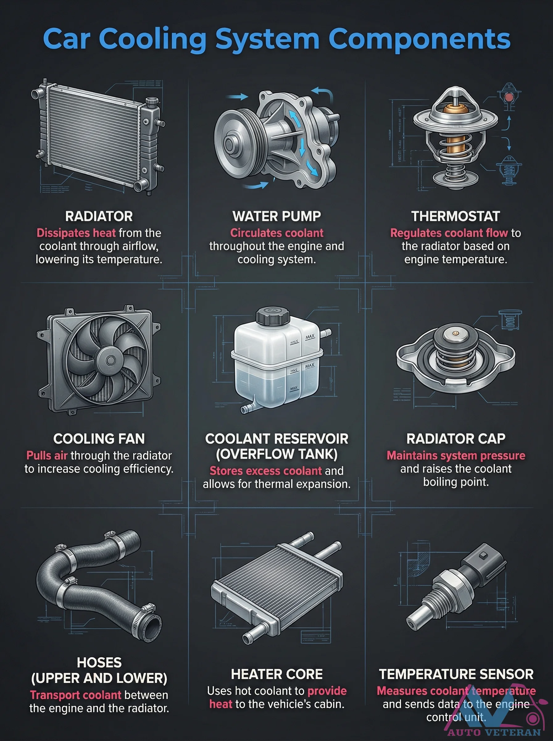
Car Cooling System Components and Functions
A detailed breakdown of the essential components that make up an automotive cooling system, including the radiator that dissipates heat from coolant through airflow, the water pump that circulates coolant throughout the engine, and the thermostat that regulates coolant flow based on engine temperature. Other critical parts shown are the cooling fan that pulls air through the radiator for increased efficiency, the coolant reservoir that stores excess fluid and allows for thermal expansion, and the radiator cap that maintains system pressure to raise the coolant boiling point. The system also includes upper and lower hoses that transport coolant between components, the heater core that uses hot coolant to provide cabin warmth, and the temperature sensor that measures coolant temperature and sends data to the engine control unit.
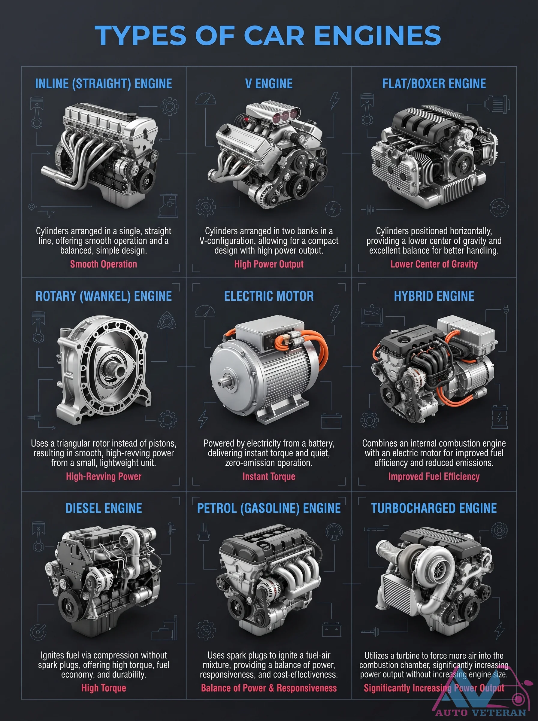
Car Engine Types Diagram and Comparison
This diagram illustrates the key characteristics of various car engine types, including inline, V, flat, rotary, electric, hybrid, diesel, petrol, and turbocharged engines. Each engine type is described with its unique features, such as smooth operation for inline engines, high power output for V engines, lower center of gravity for flat engines, high revving power for rotary engines, instant torque for electric motors, improved fuel efficiency for hybrids, high torque for diesel engines, balance of power for petrol engines, and significantly increased power output for turbocharged engines. The comparison highlights the design principles and performance benefits that define modern automotive propulsion systems.
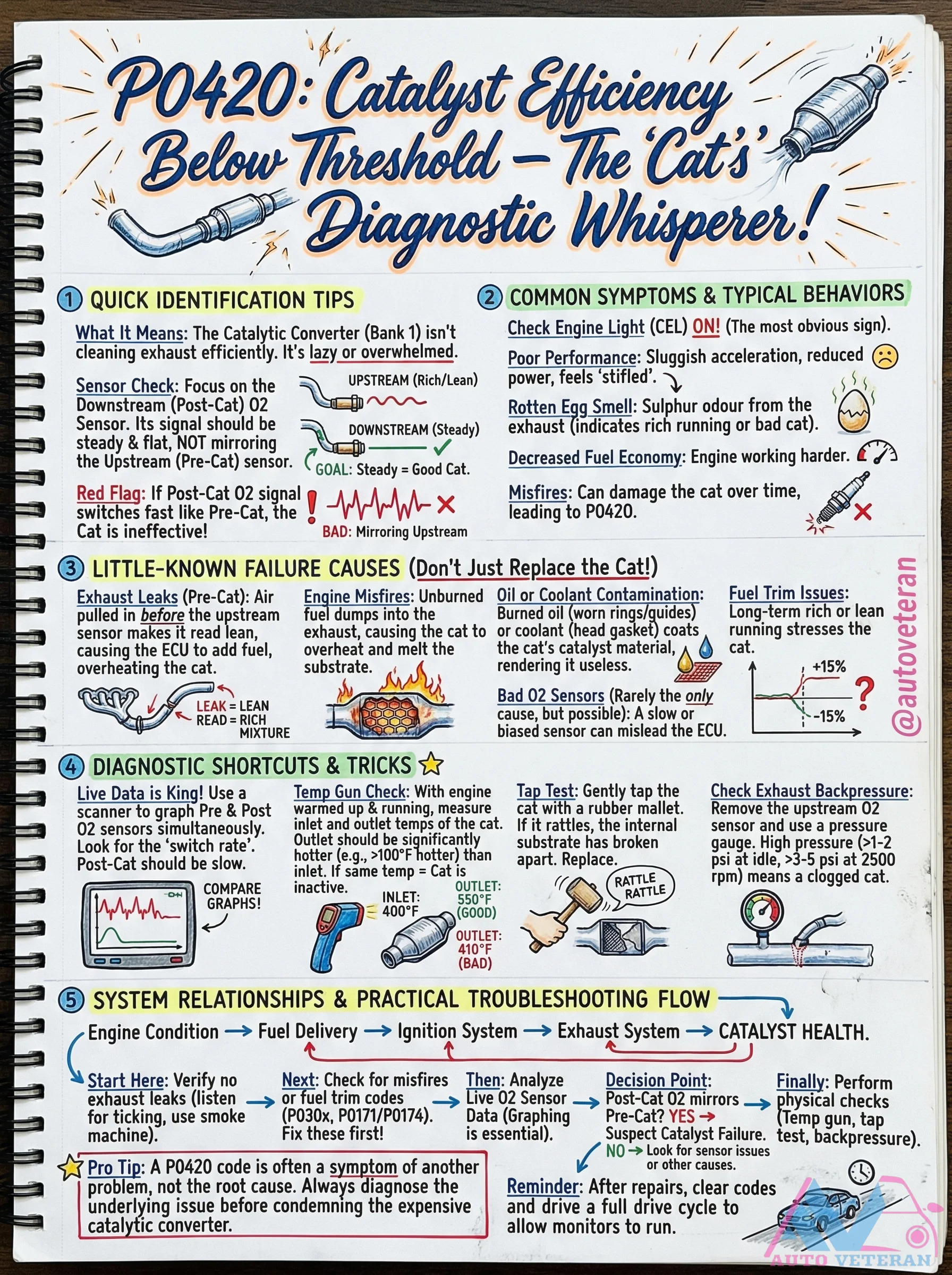
Catalytic Converter Bank 1 Diagnostic Symptoms and Tests
When your Check Engine Light illuminates with P0420 codes, the catalytic converter in Bank 1 may be failing to clean exhaust efficiently. Common symptoms include sluggish acceleration, reduced power, a rotten sulfur smell from the exhaust, and decreased fuel economy. Diagnostic shortcuts reveal critical insights: use a scanner to graph upstream and downstream oxygen sensor signals simultaneously, looking for the downstream sensor mirroring the upstream switching pattern instead of remaining steady and flat. Perform physical tests like measuring inlet and outlet temperatures with an infrared thermometer, tapping the converter with a rubber mallet to check for internal substrate damage, and checking exhaust backpressure with a pressure gauge. Remember that catalytic converter failure is often a symptom of underlying issues like exhaust leaks, engine misfires, oil or coolant contamination, or fuel trim problems, so always diagnose the root cause before replacing this expensive component.
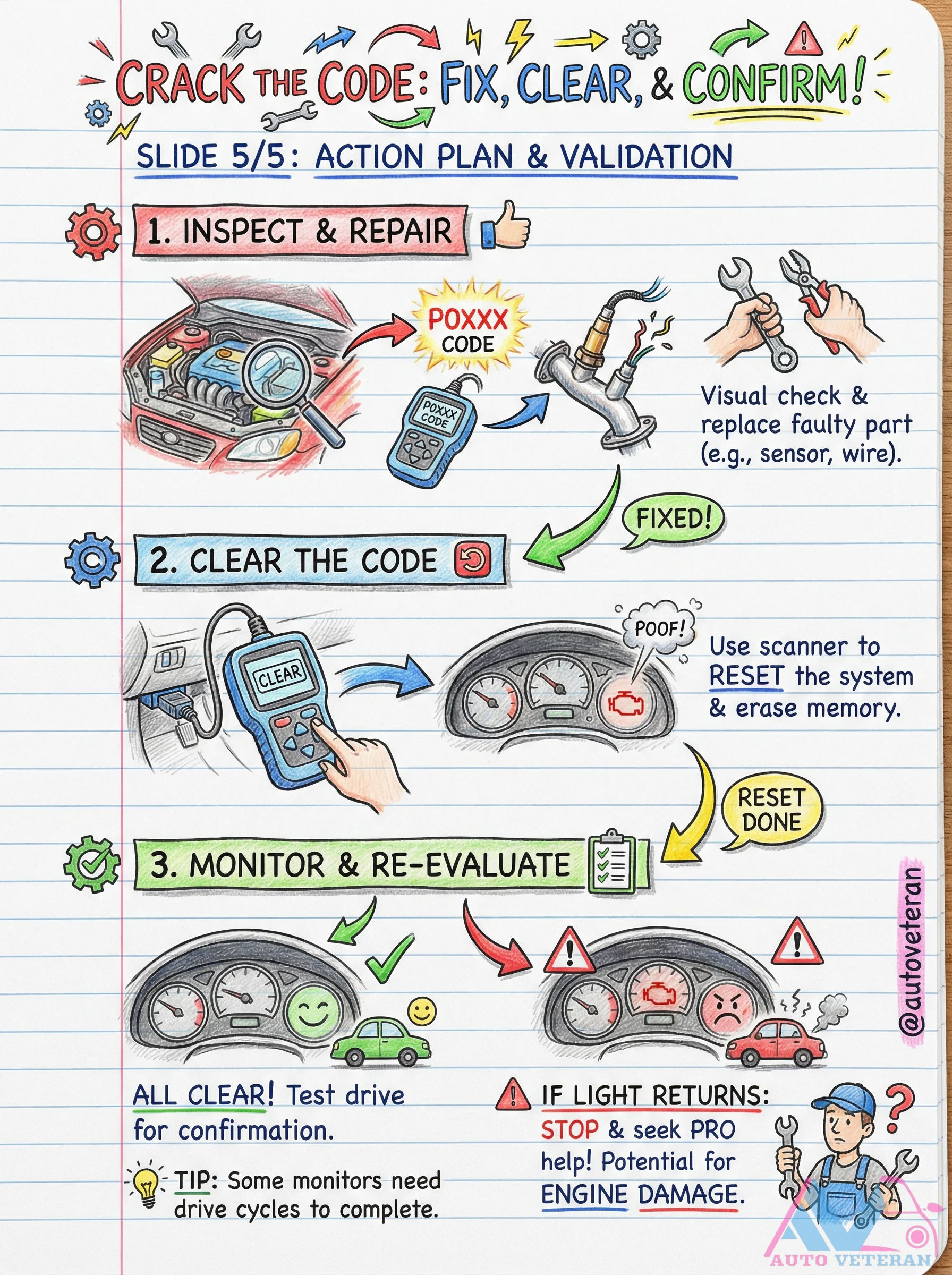
Check Engine Light Action Plan and Validation
After addressing a P0XXX diagnostic trouble code through inspection and repair, the critical final steps involve clearing the code with a scanner, then monitoring the system through a test drive to confirm the fix is permanent; if the light returns, immediate professional help is essential to prevent potential engine damage, as some monitors require multiple drive cycles to complete their self-tests.
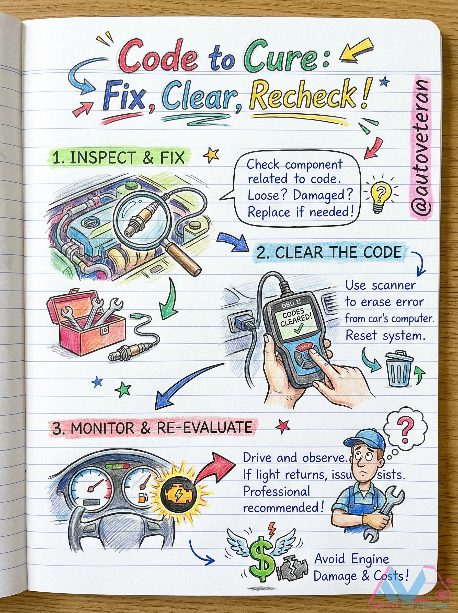
Check Engine Light Clear and Recheck Procedure
After addressing the underlying issue indicated by a diagnostic trouble code, follow this three-step process to properly clear the code and verify the repair. First, inspect and fix the specific component related to the code, checking for loose connections or damage and replacing parts as necessary. Next, use an OBD scanner to erase the error from the vehicle's computer and reset the system. Finally, monitor the vehicle by driving and observing whether the check engine light returns; if it does, the issue persists and professional diagnosis is recommended. This method helps avoid potential engine damage and unnecessary repair costs by ensuring codes are truly cleared and problems are fully resolved.
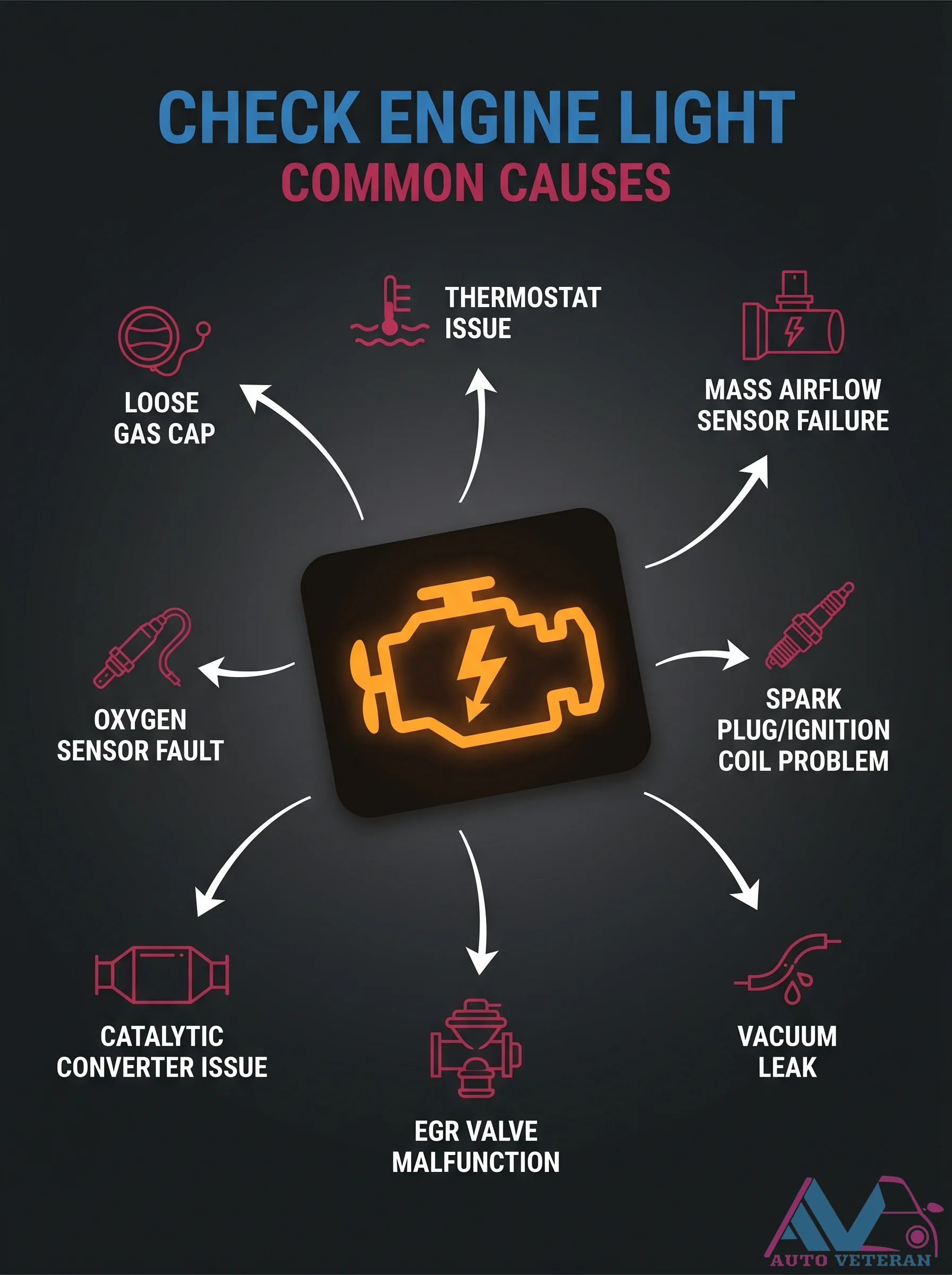
Check Engine Light Common Causes
Your check engine light can illuminate for many reasons, but common culprits include a faulty mass airflow sensor, loose gas cap, thermostat issues, failing oxygen sensor, spark plug or ignition coil problems, a clogged catalytic converter, vacuum leaks, or a malfunctioning EGR valve. Understanding these frequent triggers helps you diagnose and fix the underlying issue quickly.
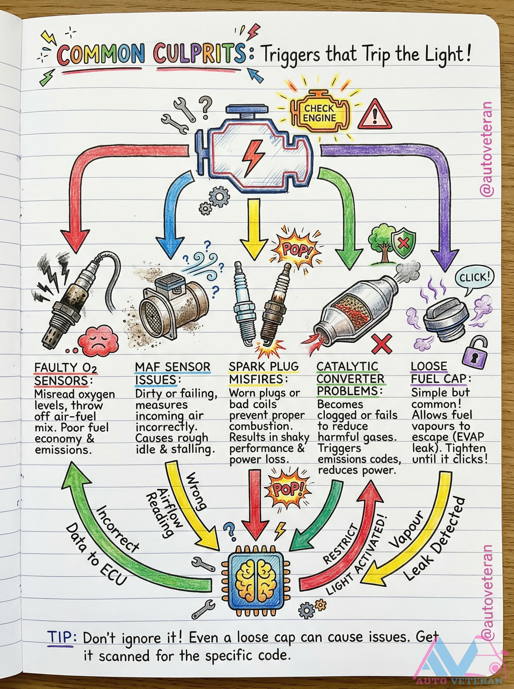
Check Engine Light Common Culprits and Causes
When your check engine light illuminates, several common issues are often to blame. A faulty oxygen sensor can misread oxygen levels and disrupt the air-fuel mix, leading to poor fuel economy and increased emissions. A dirty or failing MAF sensor may measure air intake inaccurately, resulting in shaky idle and power loss. Worn spark plugs or bad ignition coils cause misfires that affect performance. Catalytic converter problems, such as clogging, reduce engine efficiency and emissions control. Even a loose fuel cap can trigger EVAP leak codes by allowing fuel vapors to escape. Always scan for specific diagnostic codes to pinpoint the exact issue, as ignoring the light can worsen problems over time.
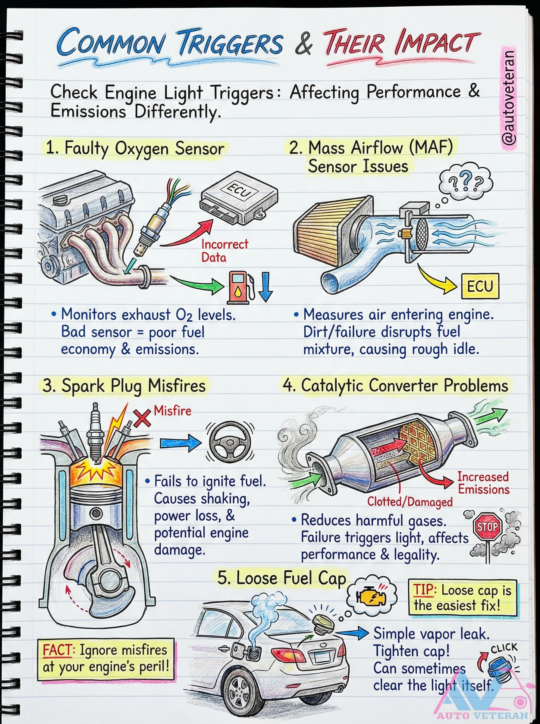
Check Engine Light Common Triggers and Their Impact
Understanding the most frequent causes of a check engine light activation reveals how each issue uniquely affects vehicle performance and emissions. A faulty oxygen sensor provides incorrect data to the ECU, leading to poor fuel economy and increased emissions. Mass Airflow Sensor problems, often from dirt or failure, disrupt the air-fuel mixture and cause rough idle. Spark misfires result in shaking and power loss, while catalytic converter issues reduce harmful gas conversion and can affect legality. A loose fuel cap, though an easy fix, creates vapor leaks. Ignoring misfires risks engine damage, and sometimes tightening the cap can clear the light itself.
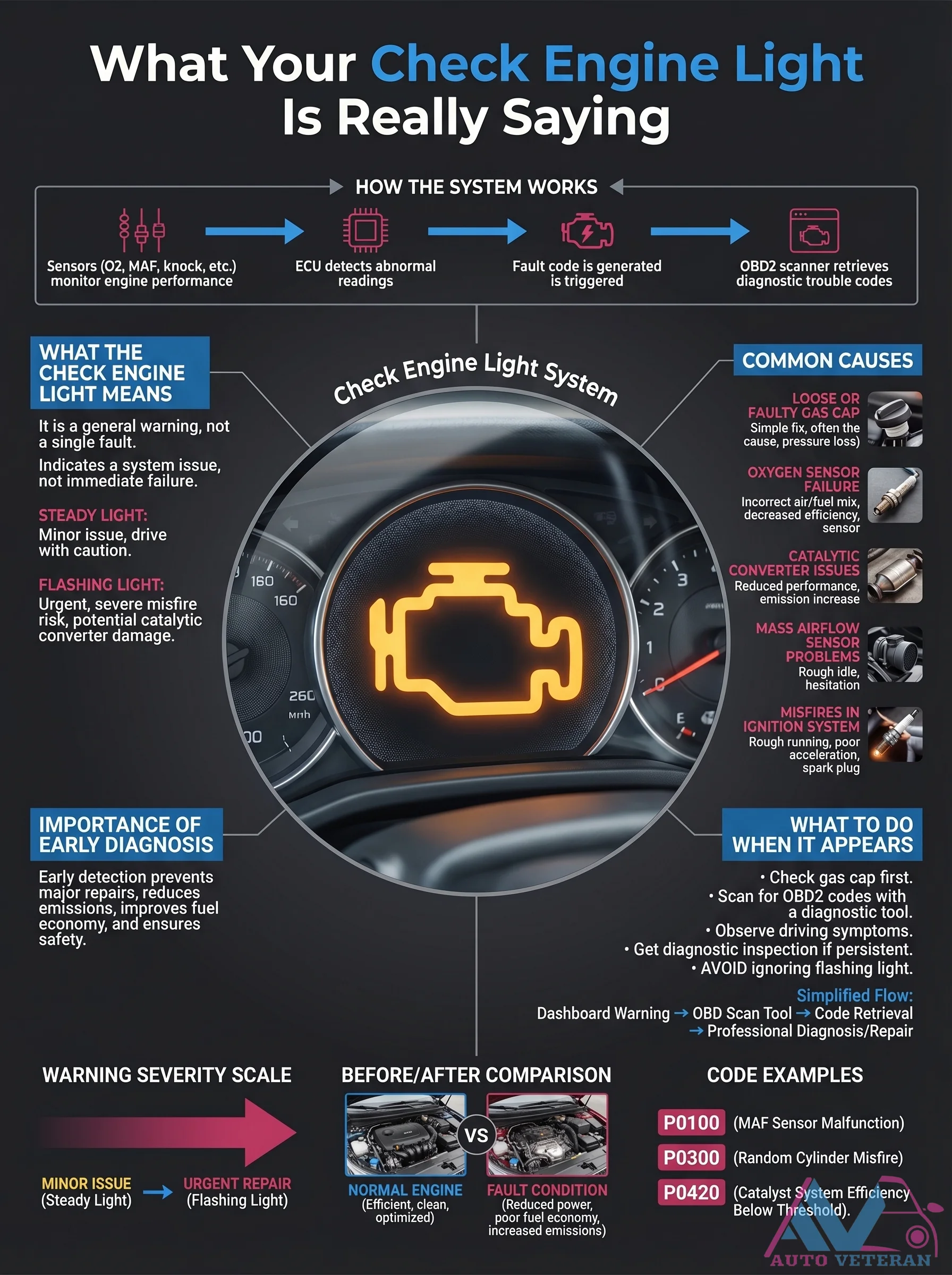
Check Engine Light Diagnostic System and OBD2 Codes
Your vehicle's check engine light serves as a critical communication tool between onboard sensors and the driver. When triggered, the Engine Control Unit detects abnormal readings from oxygen, mass airflow, or knock sensors, generating specific diagnostic trouble codes. A steady light indicates minor issues like a loose gas cap or early sensor failure, while a flashing light warns of severe problems such as catalytic converter damage or ignition misfires that require immediate attention. Using an OBD2 scanner to retrieve codes like P0100 for MAF sensor malfunctions or P0300 for random cylinder misfires allows for precise diagnosis. Early detection through this system prevents major repairs, reduces emissions, and maintains optimal fuel economy and safety.
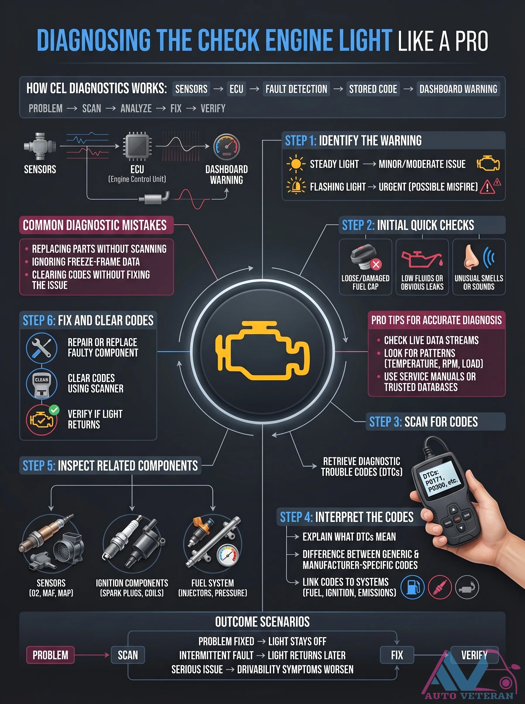
Check Engine Light Diagnostics Step-by-Step Guide
Master the professional process for diagnosing a check engine light, starting with identifying the warning type, such as a steady or flashing light indicating minor or urgent issues like misfires. Proceed with initial quick checks for loose components, low fluids, or unusual smells, then scan for diagnostic trouble codes (DTCs) to retrieve and interpret them, distinguishing between generic and manufacturer-specific codes. Inspect related components in systems like sensors, ignition, and fuel, and fix the problem by repairing or replacing faulty parts while using live data streams and service manuals for accuracy. Finally, clear the codes and verify if the light returns, ensuring a thorough resolution without common mistakes like replacing parts without scanning or ignoring freeze frame data.
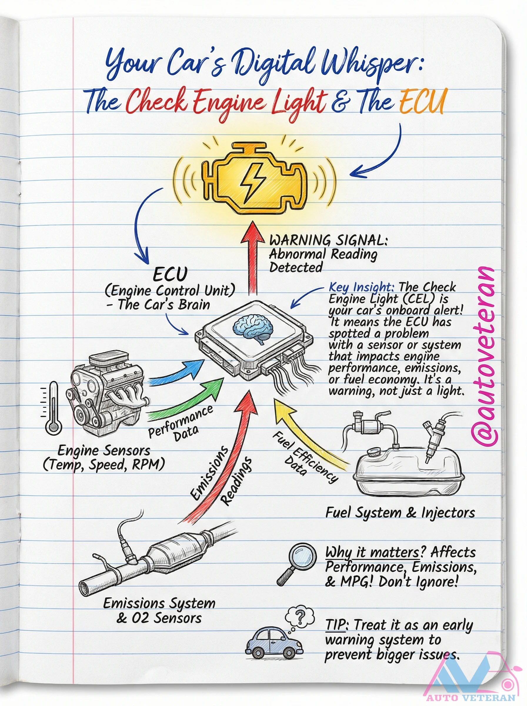
Check Engine Light ECU Warning Signal Abnormal Reading
The Check Engine Light is your car's digital warning signal from the Engine Control Unit, indicating it has detected an abnormal reading from a sensor or system. This alert affects critical performance aspects like engine speed, RPM, fuel injection, emissions, and fuel efficiency. Treat it as an early warning to prevent bigger issues with your vehicle's operation.
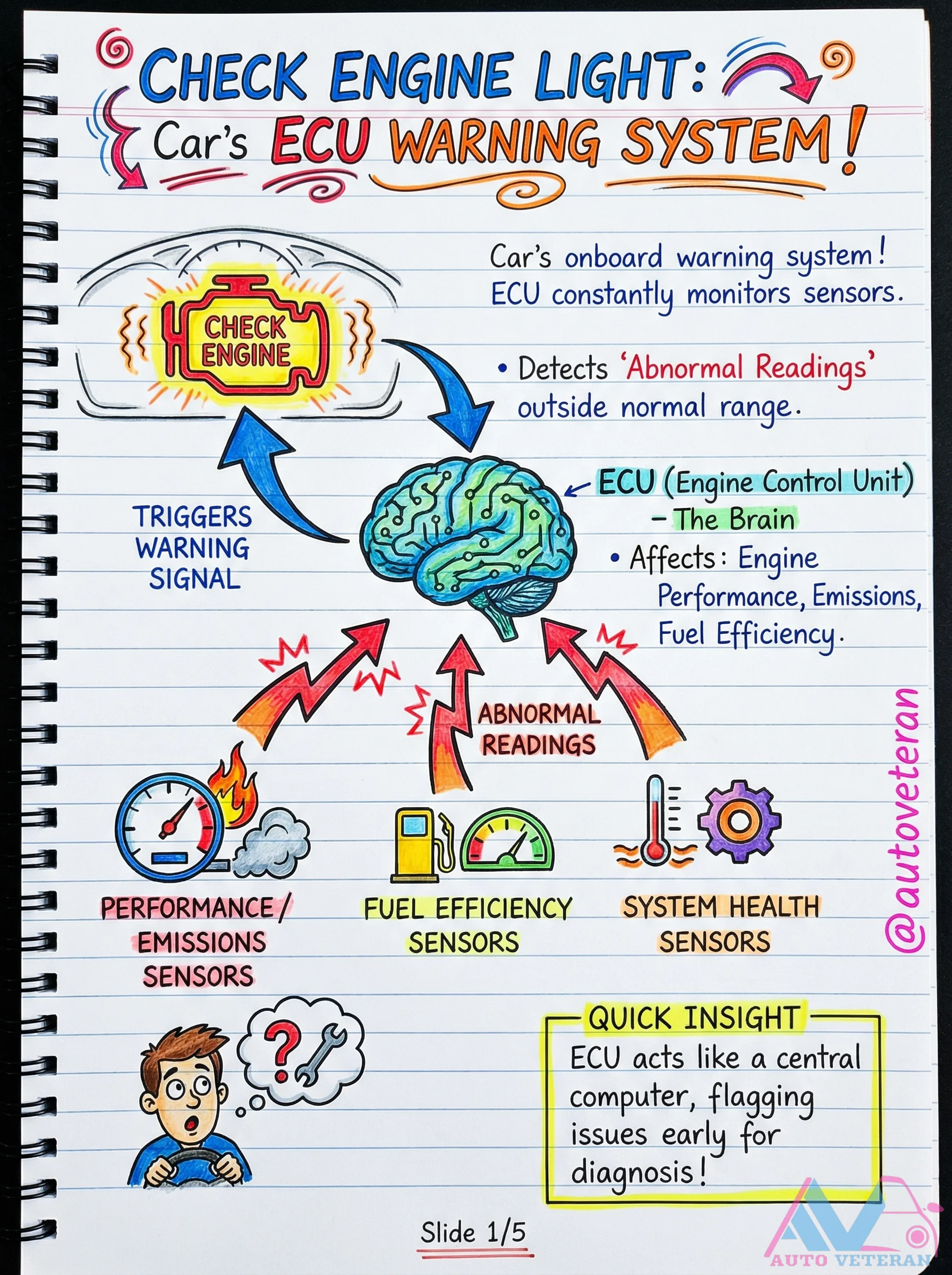
Check Engine Light ECU Warning System Explained
The Check Engine Light serves as your car's primary warning system, activated when the Engine Control Unit detects abnormal sensor readings that fall outside normal operating ranges. This early alert system flags issues affecting engine performance, fuel efficiency, emissions, and overall system health, allowing for timely diagnosis before problems escalate.
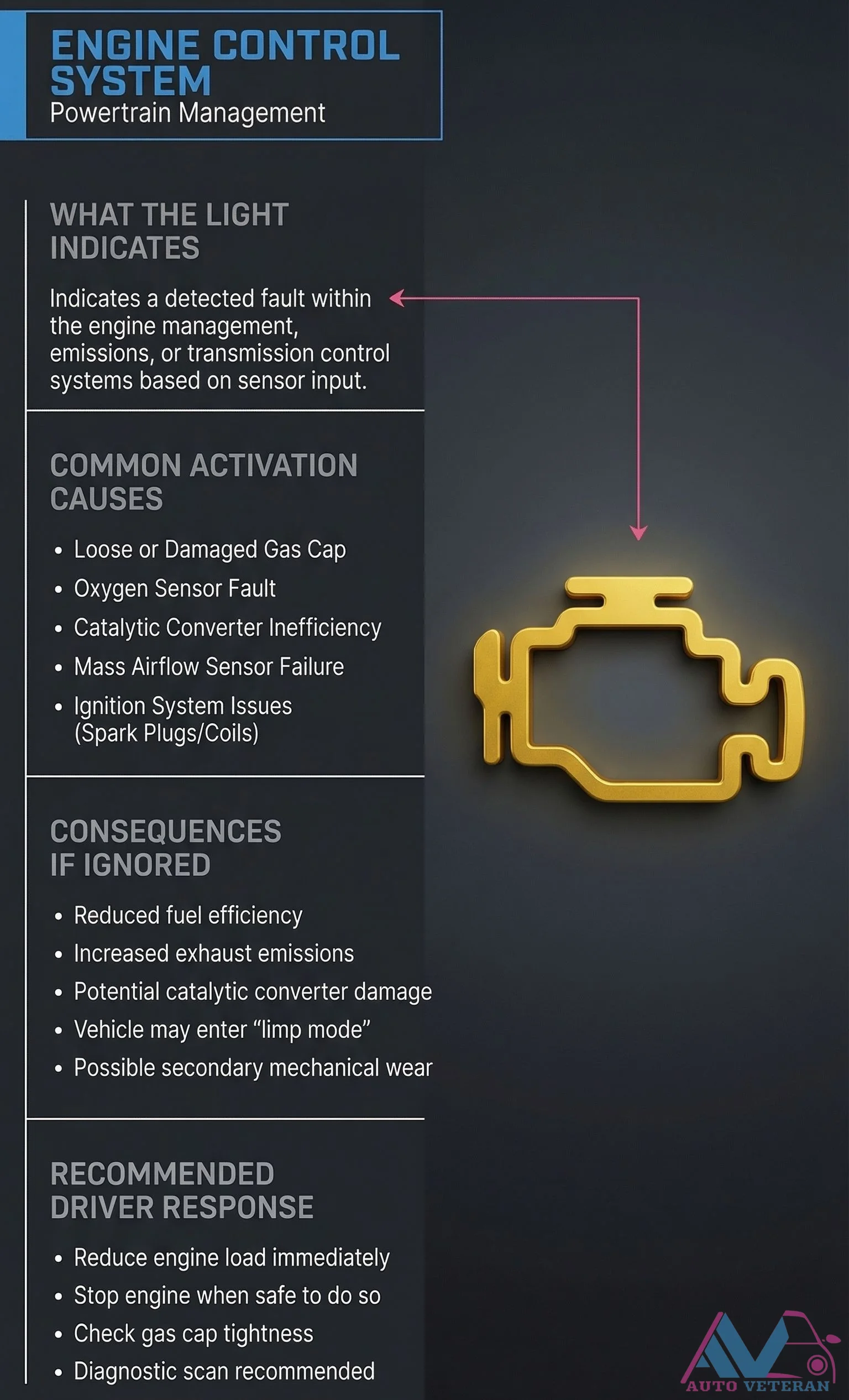
Check Engine Light Fault Indications and Common Causes
When your vehicle's check engine light illuminates, it signals a detected fault within the engine management, emissions, or transmission control systems based on sensor input. Common activation causes include a loose or damaged gas cap, oxygen sensor fault, catalytic converter inefficiency, mass airflow sensor failure, or ignition system issues with spark plugs or coils. Ignoring this warning can lead to reduced fuel efficiency, increased exhaust emissions, potential catalytic converter damage, the vehicle entering limp mode, and possible secondary mechanical wear. The recommended driver response is to reduce engine load immediately, stop the engine when safe, check gas cap tightness, and obtain a diagnostic scan to identify the specific issue.
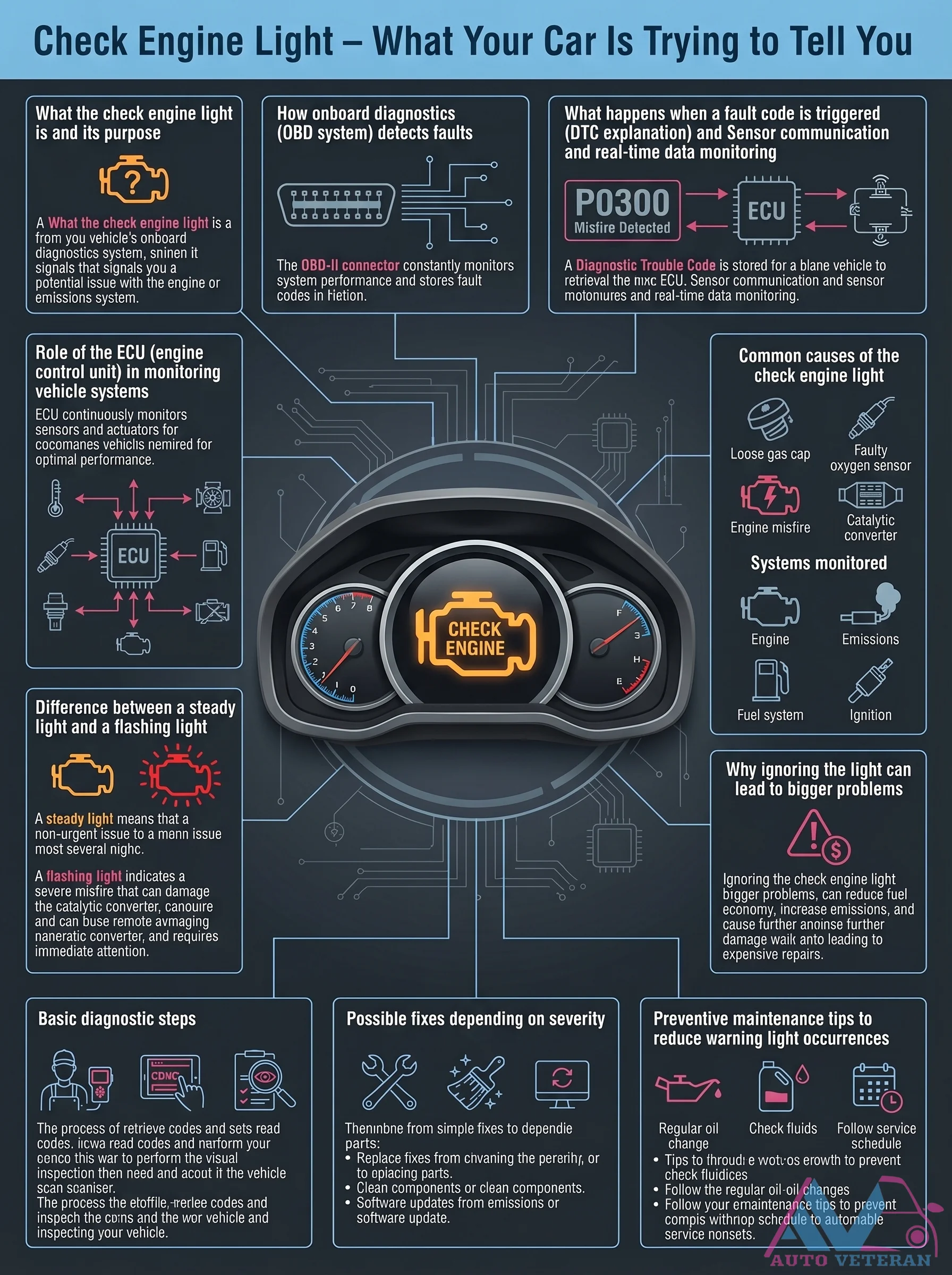
Check Engine Light OBD DTC Explanation and Monitoring
Your vehicle's onboard diagnostics system constantly monitors engine performance through sensor communication and real-time data analysis. When a fault is detected, the engine control unit stores a diagnostic trouble code, illuminating the check engine light to signal potential issues with emissions, fuel systems, or ignition components. Understanding the difference between a steady light indicating non-urgent problems and a flashing light warning of severe misfires that can damage the catalytic converter is crucial for timely intervention and preventing expensive repairs.
Check Engine Light OBD Fault Indications and Responses
The Check Engine Light activates when your vehicle's On Board Diagnostics system identifies a fault in engine, emissions, or transmission systems, typically from sensor readings or system state irregularities. Common triggers include a loose fuel cap, oxygen sensor failure, catalytic converter problems, mass airflow sensor malfunctions, or ignition coil and spark plug issues. Ignoring this warning can lead to reduced fuel economy, increased emissions, potential long term engine damage, and risk of catalytic converter failure. Recommended driver responses involve safely reducing engine load, checking the fuel cap immediately, scheduling a professional diagnostic scan, and avoiding prolonged driving if the light is flashing.
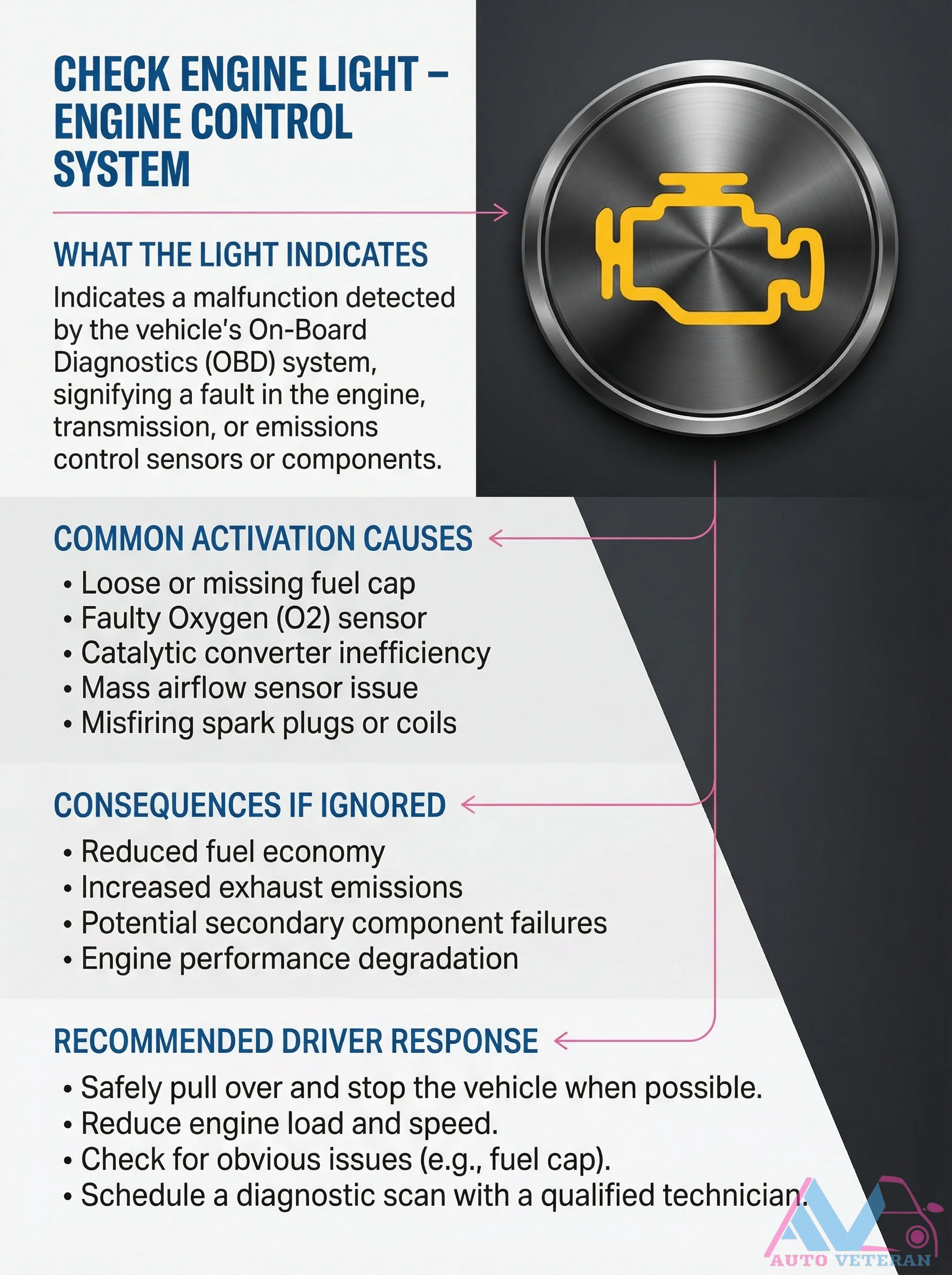
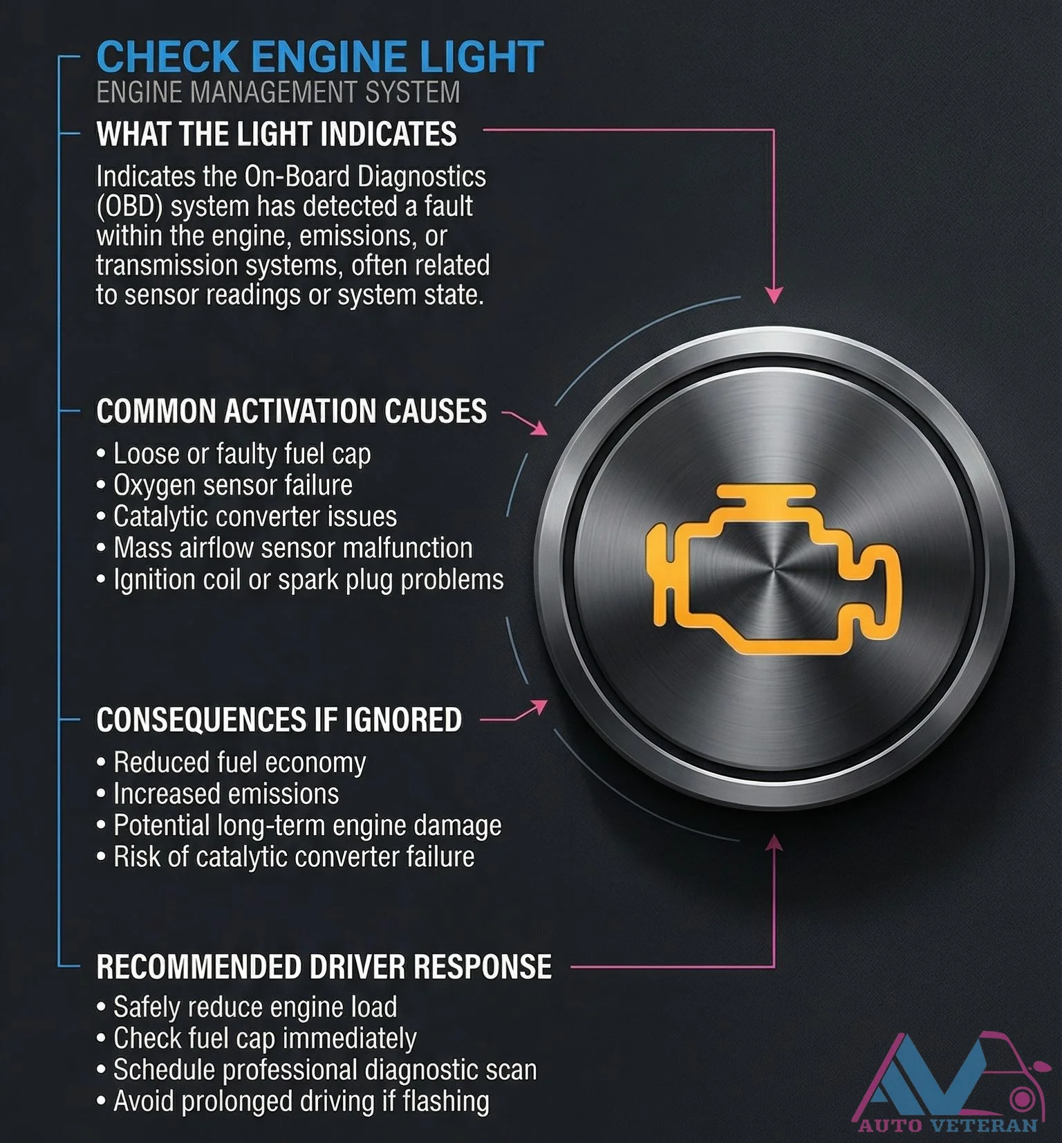
Check Engine Light OBD System Warning and Response
The Check Engine Light activates when your vehicle's On Board Diagnostics system detects a malfunction in engine, transmission, or emissions control components. Common triggers include a loose fuel cap, faulty oxygen sensor, catalytic converter inefficiency, mass airflow sensor issues, or misfiring spark plugs. Ignoring this warning can lead to reduced fuel economy, increased emissions, potential secondary failures, and engine performance degradation. When the light appears, safely pull over when possible, reduce engine load and speed, check for obvious issues like the fuel cap, and schedule a diagnostic scan with a qualified technician.