Interactive Explorer
Check Engine Light OBD-II Fault Codes and Causes
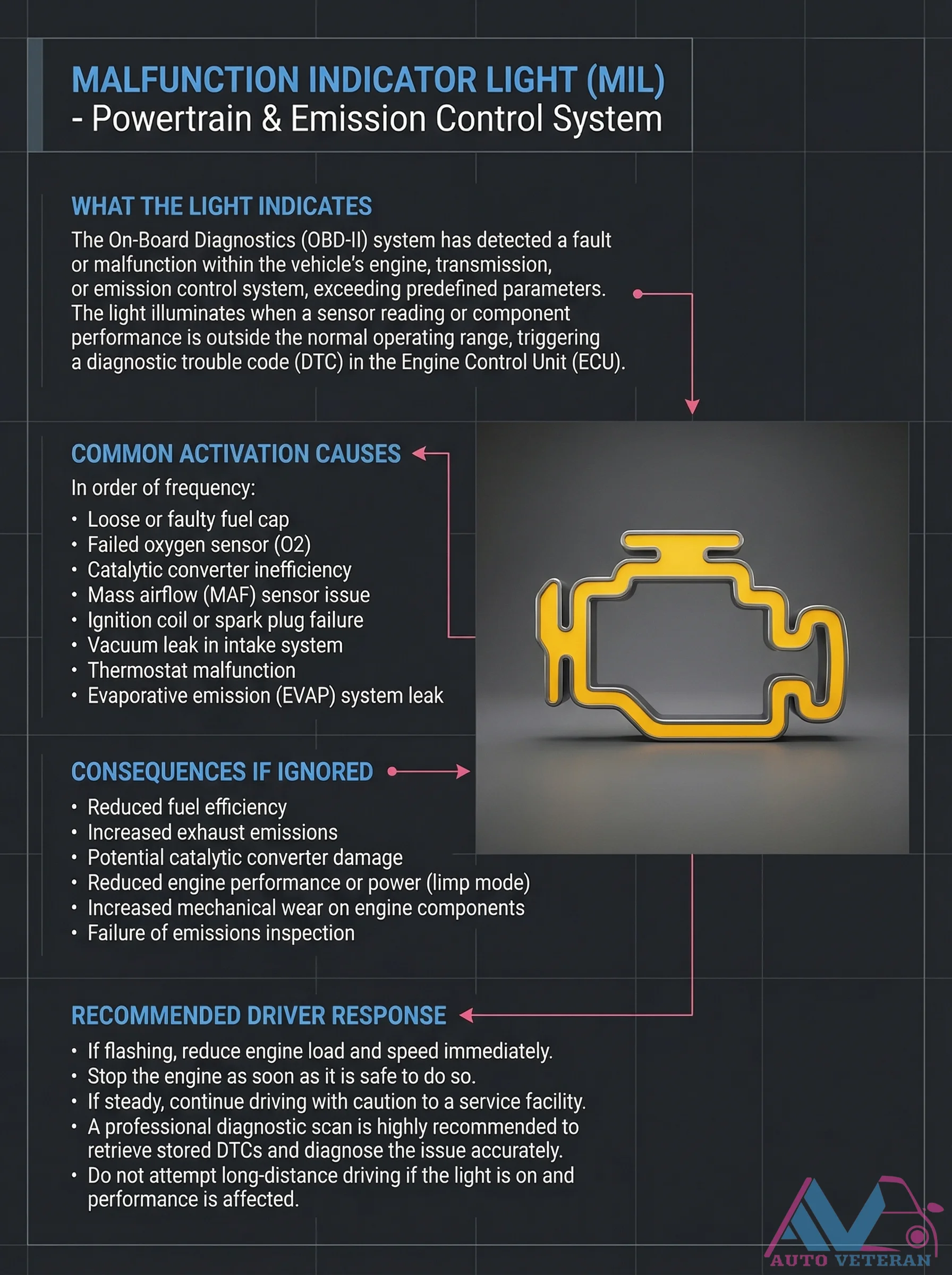
When your vehicle's Malfunction Indicator Light illuminates, the On Board Diagnostics II system has detected a fault in the powertrain or emission control system. This warning indicates that a sensor reading or component performance has exceeded normal operating parameters, triggering a Diagnostic Trouble Code in the Engine Control Unit. Common activation causes include loose fuel caps, failed oxygen sensors, catalytic converter inefficiency, mass airflow sensor issues, ignition coil failures, vacuum leaks, thermostat malfunctions, and evaporative emission system leaks. Ignoring this warning can lead to reduced fuel efficiency, increased emissions, potential catalytic converter damage, reduced engine performance, increased mechanical wear, and emissions inspection failure. If the light is flashing, immediately reduce engine load and speed, then stop the engine when safe. If steady, drive cautiously to a service facility for professional diagnostic scanning to retrieve stored codes and accurately diagnose the issue.
Check Engine Light OBD-II Scanner Diagnosis Steps
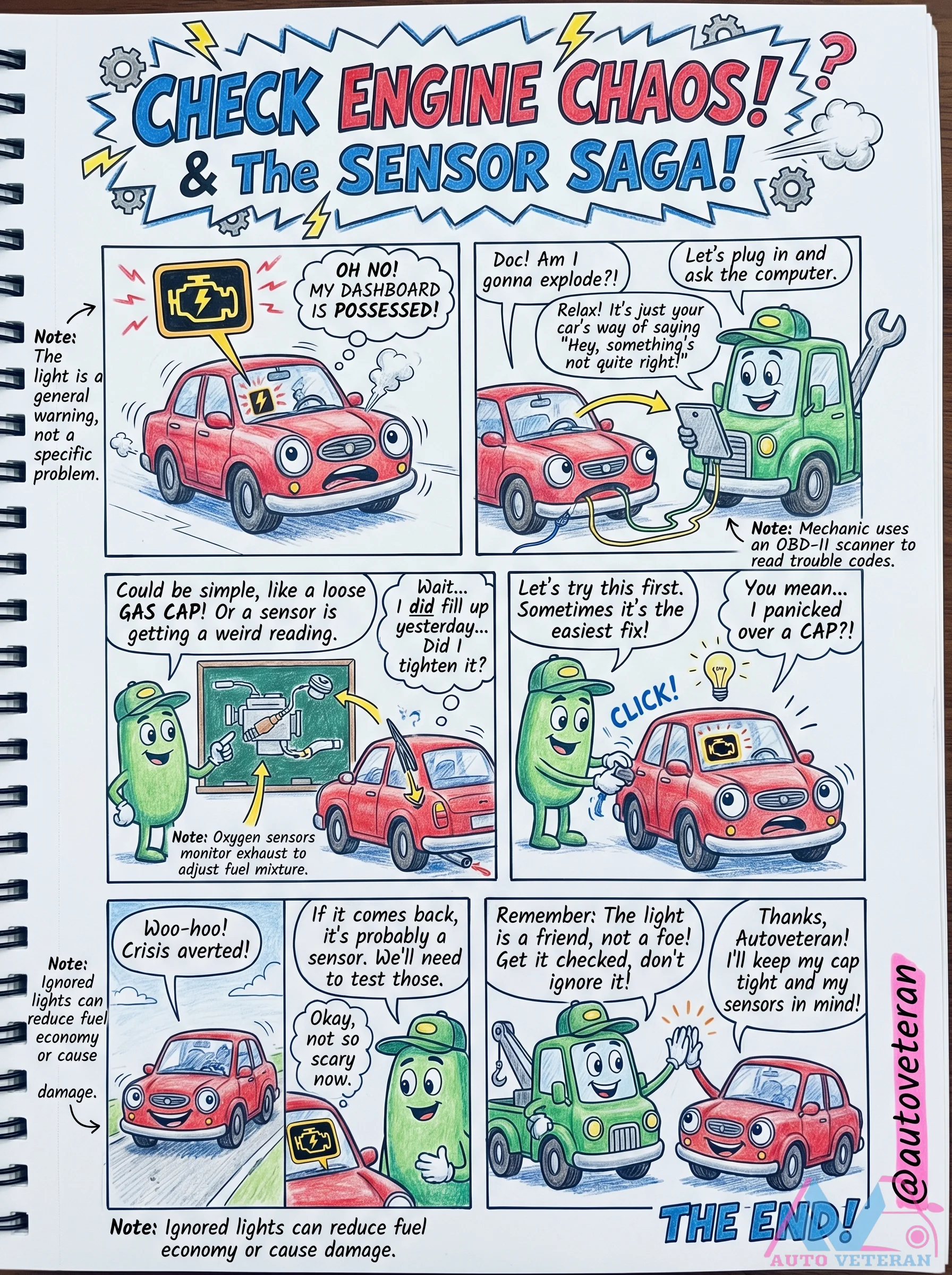
When your check engine light illuminates, it signals a general issue that requires diagnosis; start by tightening your gas cap, as this simple fix often resolves the problem. If the light persists, use an OBD-II scanner to read trouble codes, which could indicate sensor malfunctions like oxygen sensors monitoring exhaust to adjust fuel mixture. Ignoring the warning can reduce fuel economy or cause engine damage, so address it promptly to maintain vehicle performance.
Check Engine Light OBD-II Warning Causes and Response
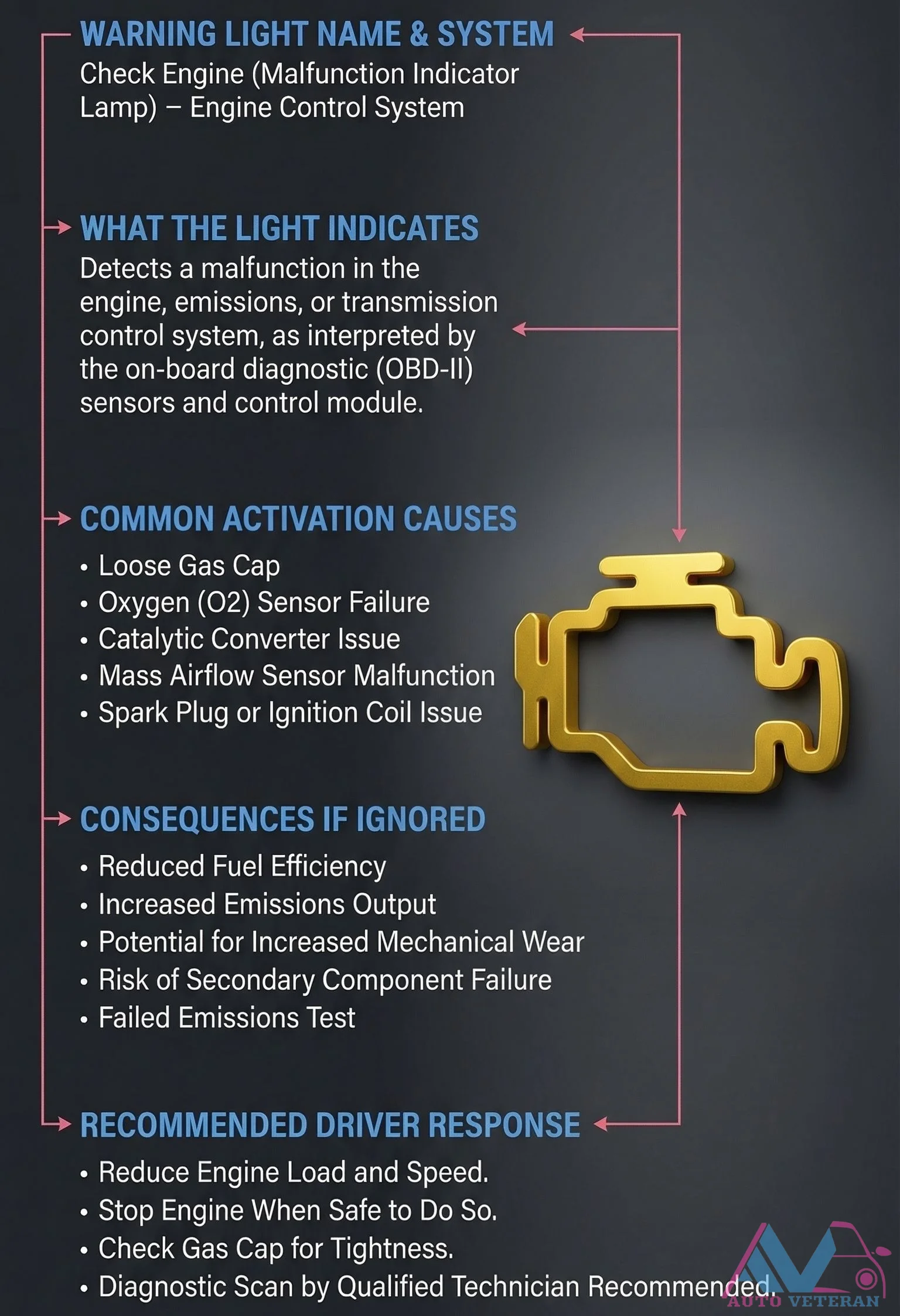
The Check Engine Light, also known as the Malfunction Indicator Lamp, activates when your vehicle's OBD-II system detects issues in the engine, emissions, or transmission control systems. Common triggers include a loose gas cap, oxygen sensor failure, catalytic converter problems, mass airflow sensor malfunctions, or spark/ignition coil issues. Ignoring this warning can lead to reduced fuel efficiency, increased emissions, potential mechanical wear, risk of secondary component failure, and failed emissions tests. Recommended driver responses include reducing engine load and speed when safe, checking the gas cap for tightness, and seeking a diagnostic scan from a qualified technician.
Check Engine Light OBD2 Diagnosis and Common Codes
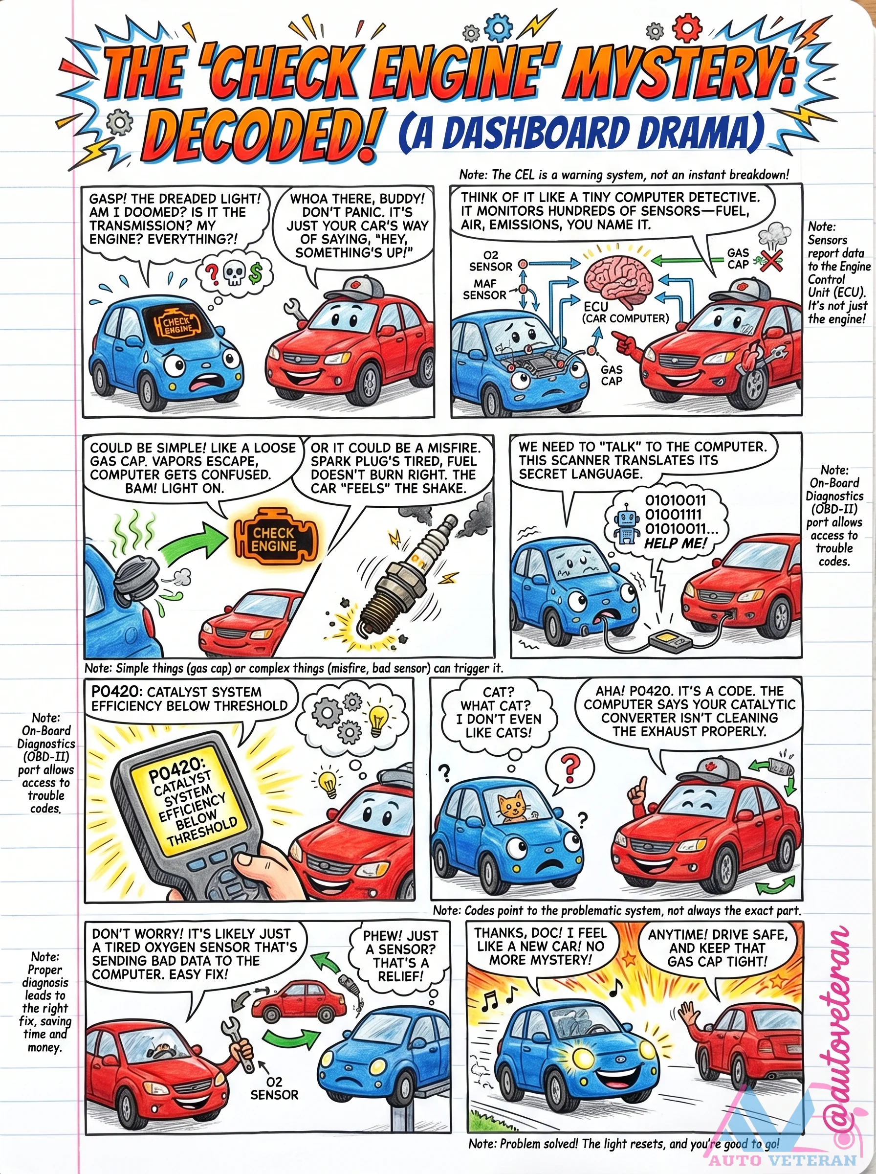
When the Check Engine Light illuminates on your dashboard, it signals that your vehicle's onboard computer has detected an issue within its monitoring systems. This warning light is not an immediate breakdown indicator but rather your car's way of communicating that something requires attention. The Engine Control Unit continuously monitors hundreds of sensors throughout the engine, fuel system, transmission, and emissions components. To properly diagnose the problem, you need to access the vehicle's diagnostic system through the OBD2 port using a scanner tool. This device translates the computer's trouble codes into understandable information. Common issues range from simple fixes like a loose gas cap allowing fuel vapors to escape, to more complex problems like misfires, bad sensors, or catalytic converter efficiency below threshold indicated by codes such as P0420. The scanner helps pinpoint whether the issue involves oxygen sensors sending incorrect data, fuel system irregularities, or other components. Once identified and resolved, the light can be reset, restoring normal operation and preventing unnecessary repairs.
Check Engine Light OBD2 Diagnostic Step-by-Step Guide
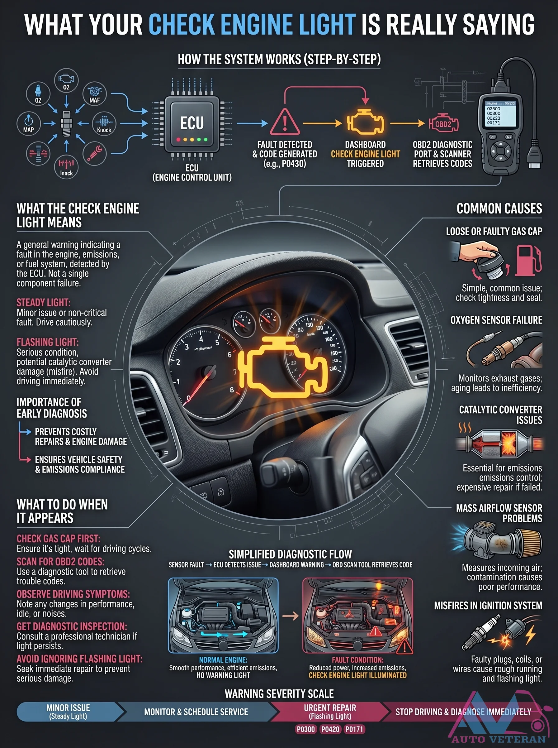
Understanding what your check engine light is really saying begins with recognizing the system's operation. The Engine Control Unit detects faults, triggers dashboard warnings, and generates OBD2 diagnostic codes like P0430. A steady light indicates minor issues such as a loose gas cap or oxygen sensor failure, requiring cautious driving and inspection. A flashing light signals serious conditions like catalytic converter damage or misfires, demanding immediate repair to prevent costly engine damage. The diagnostic flow involves checking the gas cap first, scanning for codes with a diagnostic tool, observing driving symptoms like poor performance or rough idle, and consulting a professional technician if the light persists. Early diagnosis ensures vehicle safety, emissions compliance, and prevents expensive repairs by addressing issues from minor warnings to urgent stop-driving alerts.
Check Engine Light Powertrain Control System Activation
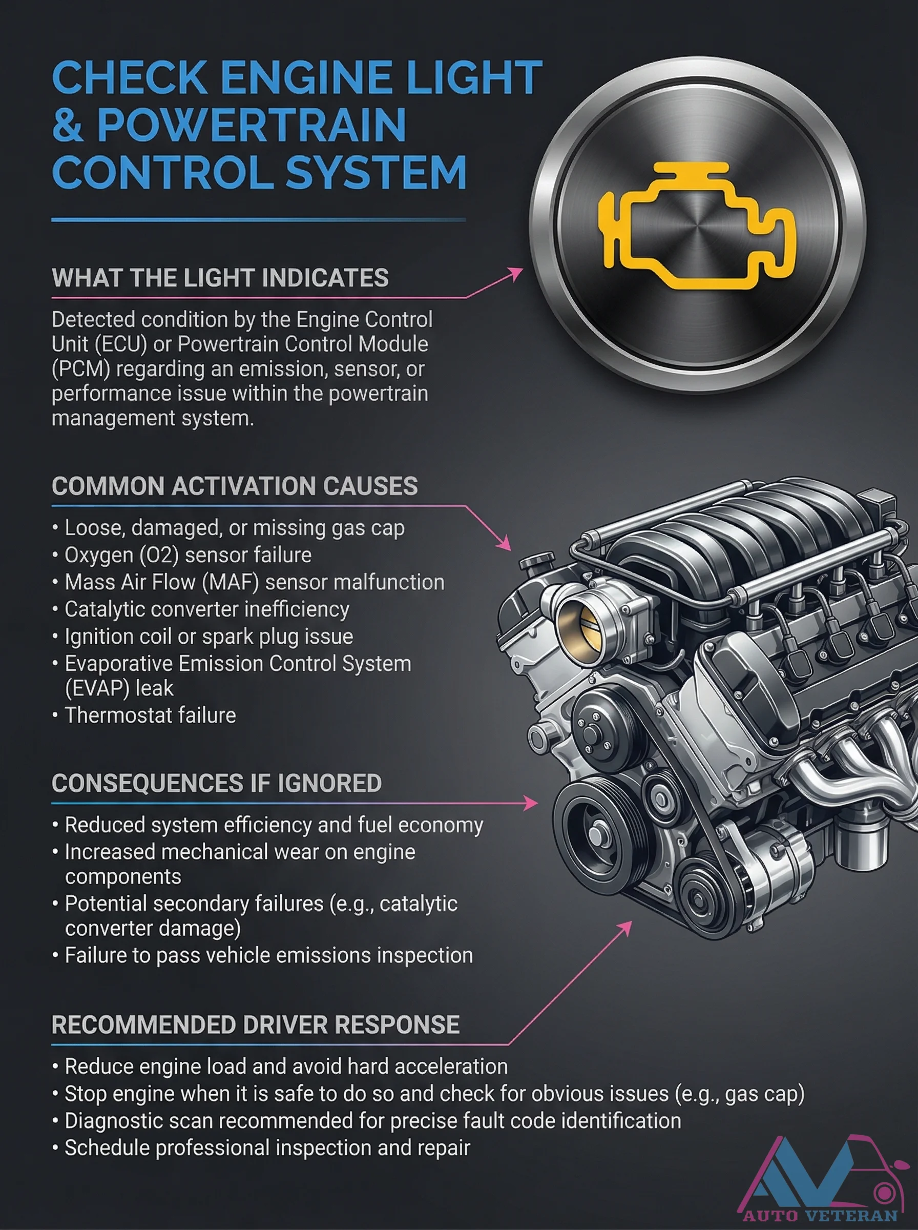
When your Check Engine Light illuminates, it signals that the Engine Control Unit or Powertrain Control Module has detected an emission, sensor, or performance issue within the powertrain management system. Common causes include a loose gas cap, oxygen sensor failure, mass airflow sensor malfunction, catalytic converter inefficiency, ignition coil problems, EVAP system leaks, or thermostat failure. Ignoring this warning can lead to reduced fuel economy, increased engine wear, potential catalytic converter damage, and failure to pass emissions inspections. Drivers should reduce engine load, avoid hard acceleration, check for obvious issues like a loose gas cap, perform a diagnostic scan for fault codes, and schedule professional inspection and repair.
Check Engine Light Simple Fixes and Major Risks
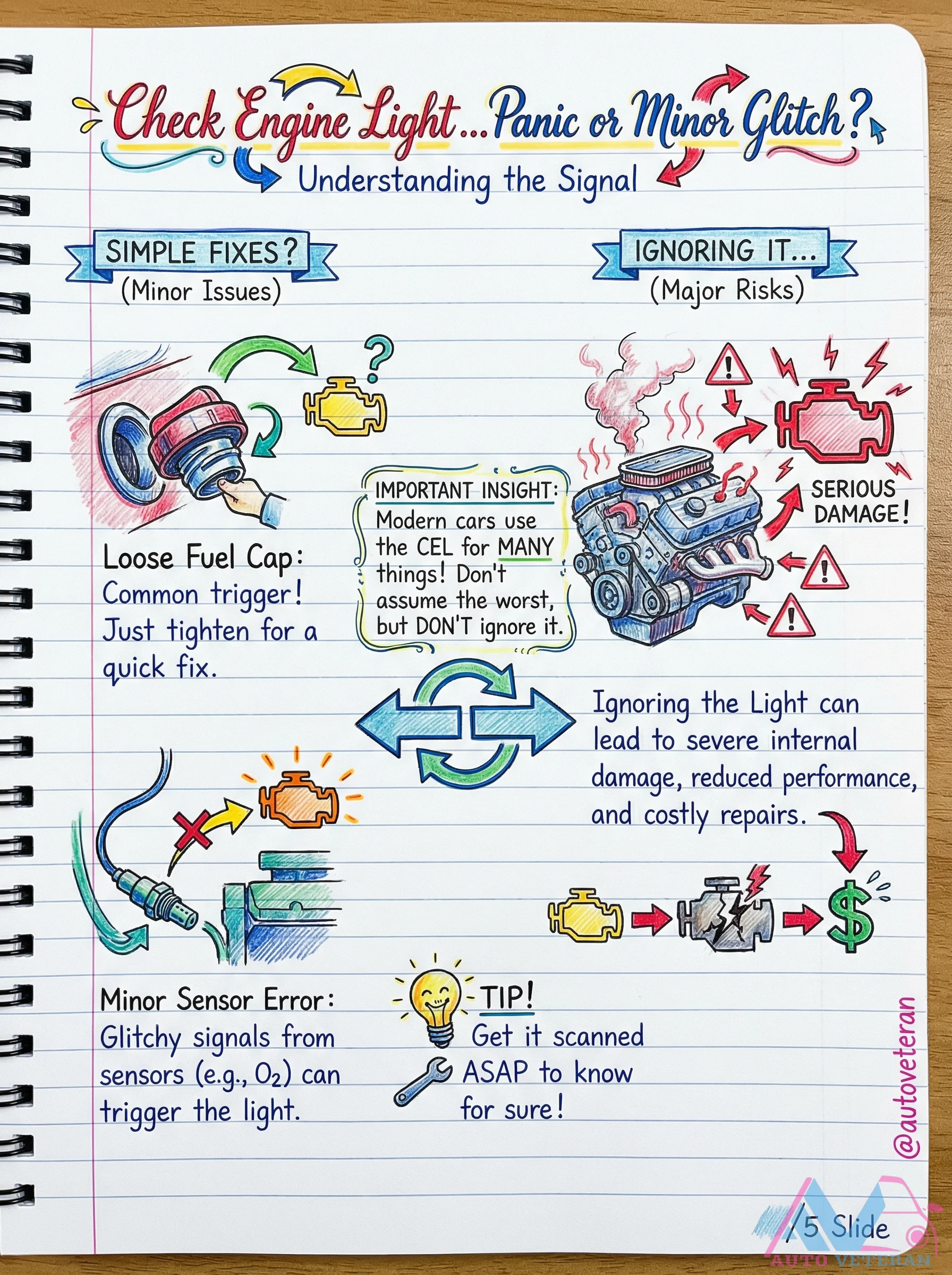
When your dashboard's Check Engine Light illuminates, it signals various issues ranging from minor sensor glitches to serious engine damage; understanding this warning is crucial as ignoring it can lead to reduced performance, costly repairs, or severe internal damage. Modern vehicles use this light for multiple diagnostic purposes, so don't panic but act promptly by getting the code scanned to identify specific triggers like a loose fuel cap or faulty oxygen sensor, then address them with appropriate fixes to prevent escalation.
Check Engine Light Simple Fixes and Serious Risks
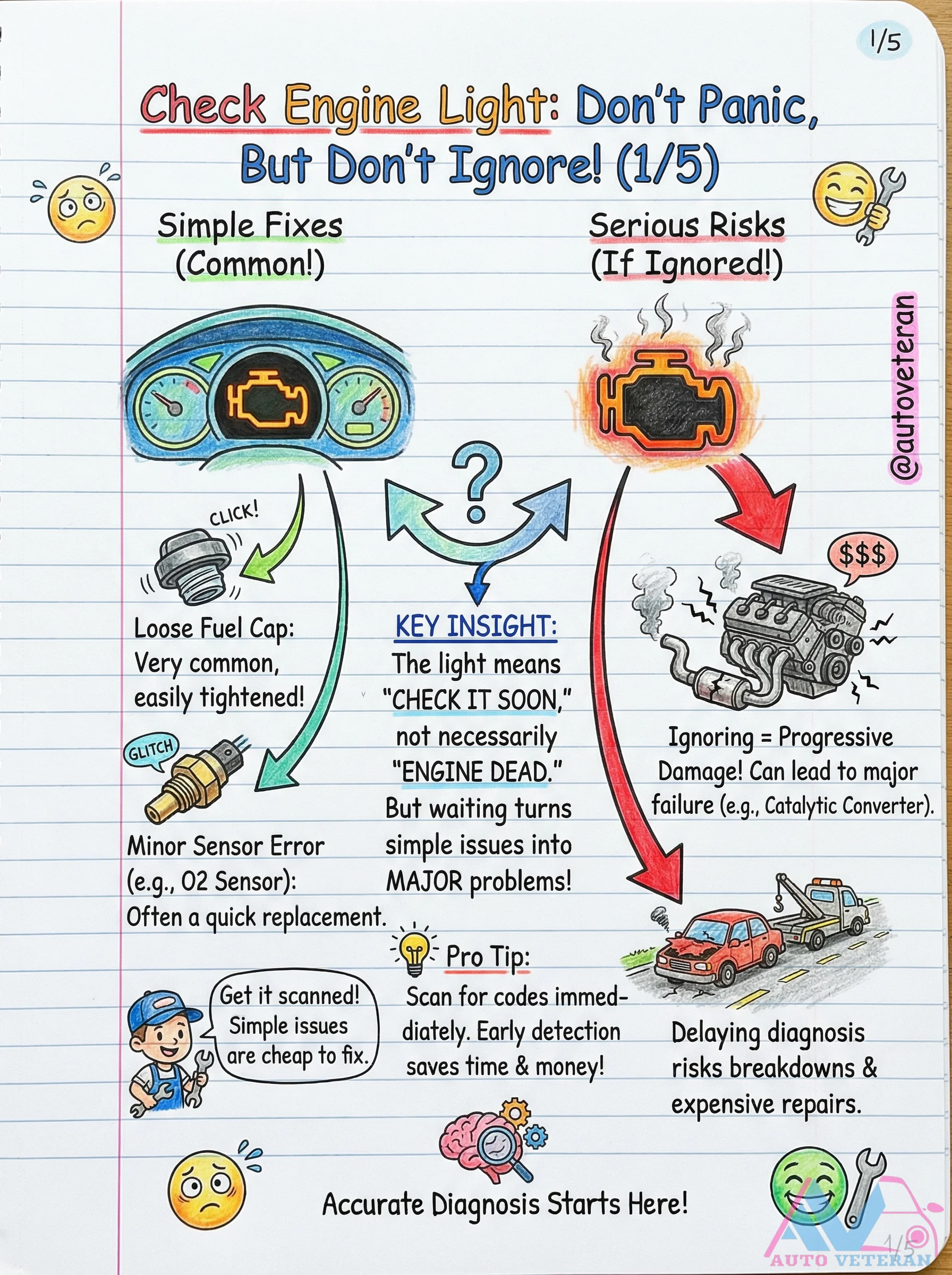
When your check engine light illuminates, immediate action is crucial; a loose fuel cap can often be tightened easily, while minor sensor errors like an O2 sensor may require quick replacement. Ignoring these warnings can transform simple issues into major problems, including progressive engine damage, catalytic converter failure, and expensive repairs. Early detection through code scanning saves both time and money, preventing breakdowns and ensuring accurate diagnosis begins promptly.

Chinese Automotive Manufacturers Overview
An infographic presenting key Chinese automakers including BYD, Geely, Great Wall Motors, Changan, SAIC Motor, NIO, XPeng, Li Auto, Dongfeng Motor, BAIC Group, Chery, and Byton. It highlights their founders, founding years, iconic vehicles, and strategic focuses ranging from EV leadership to global expansion and autonomous driving.

Clutch Basics: How It Works Step-by-Step
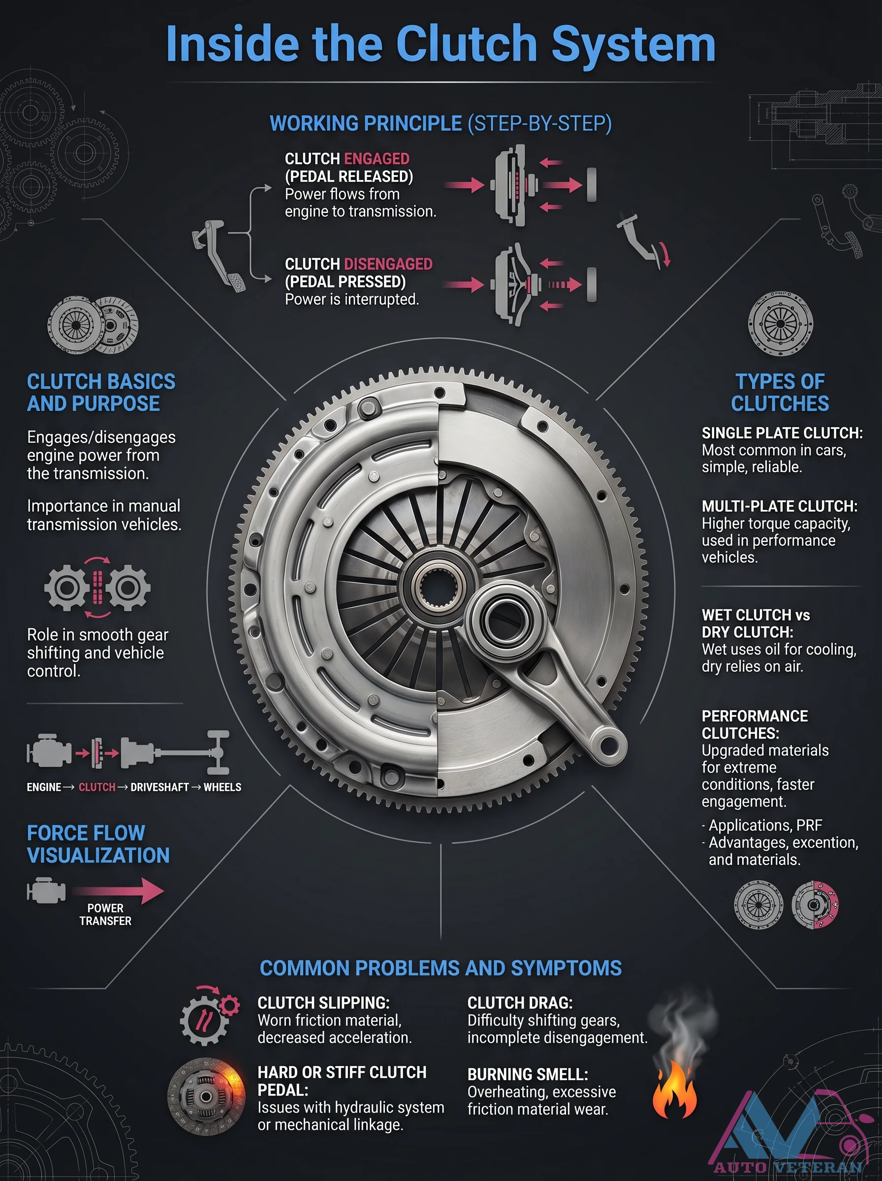
This diagram breaks down the clutch system fundamentals; showing how the clutch connects and disconnects engine power during gear changes. It covers the single plate clutch used in everyday vehicles and multi plate clutches for high performance or heavy duty applications. Key components like the clutch disc, pressure plate with diaphragm spring, release bearing, pilot bearing and flywheel are labeled. The engaged position transfers power from engine to transmission while disengaged cuts power for smooth shifts. Common issues such as clutch slipping from worn material, hard or stiff pedal, clutch drag causing difficult shifting, and burning smell from overheating are also highlighted, making this a complete visual guide for manual transmission understanding.
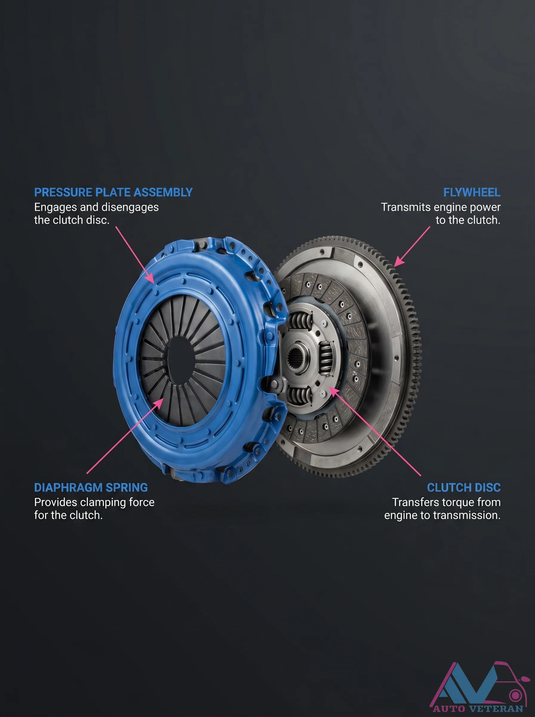
Clutch Pressure Plate Assembly Components
The pressure plate assembly works with the flywheel to engage and disengage the clutch disc. A diaphragm spring provides clamping force, ensuring the clutch disc transmits torque from the engine to the transmission smoothly.
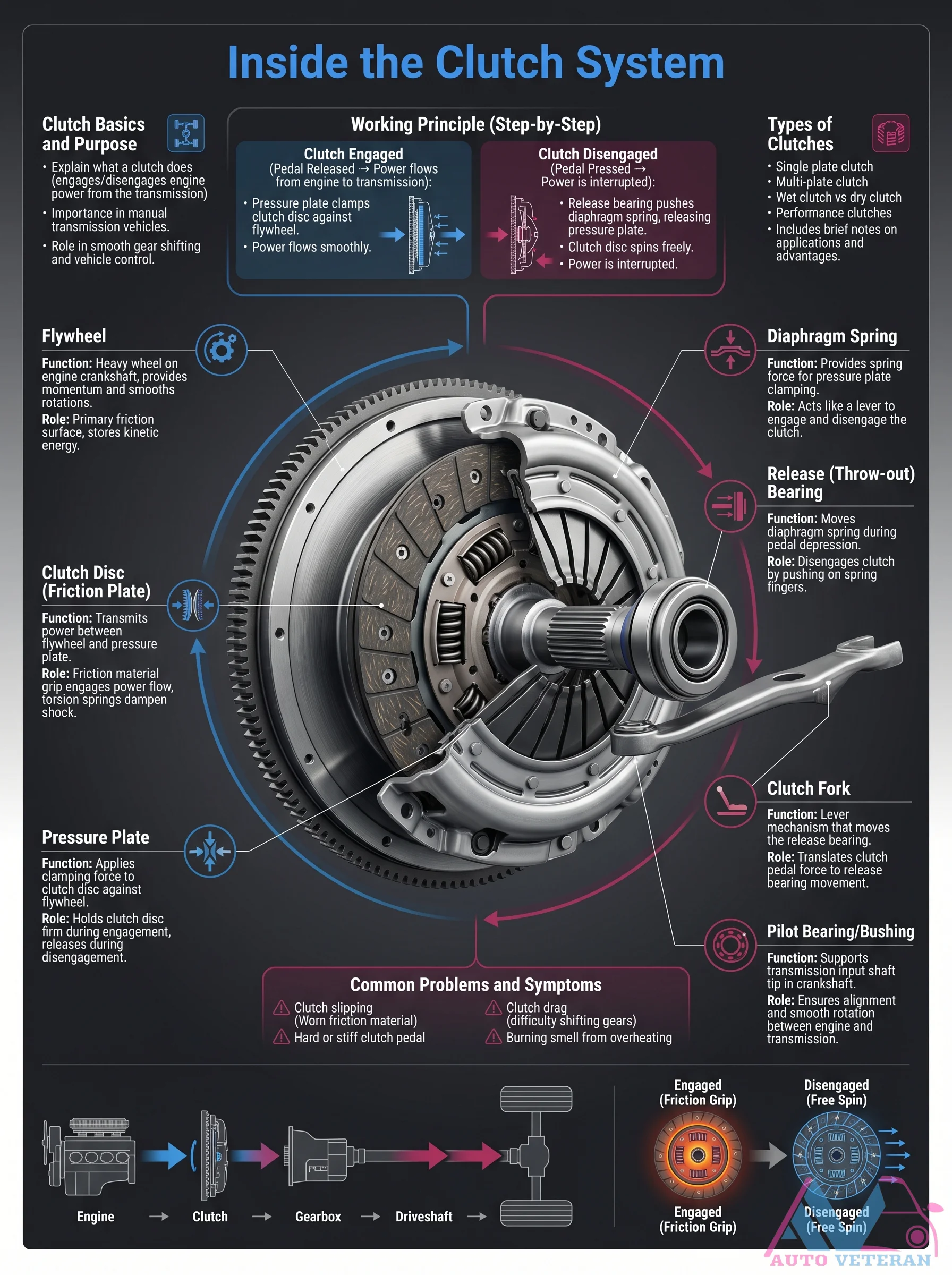
Clutch System Basics and Working Principle
The clutch system serves as the critical interface between engine power and vehicle motion, operating through a precise mechanical dance. When the clutch pedal is released, the pressure plate clamps the clutch disc against the flywheel, allowing power to flow smoothly from the engine through the transmission to the driveshaft. Depressing the pedal activates the release bearing, which pushes against the diaphragm spring to disengage the clutch disc, interrupting power transfer for gear changes. Key components like the clutch fork, pilot bearing, and tension springs work in concert to enable smooth shifting while managing kinetic energy and damping shock. Understanding this engagement and disengagement cycle is fundamental to diagnosing common issues such as clutch slipping, drag, or a stiff pedal.
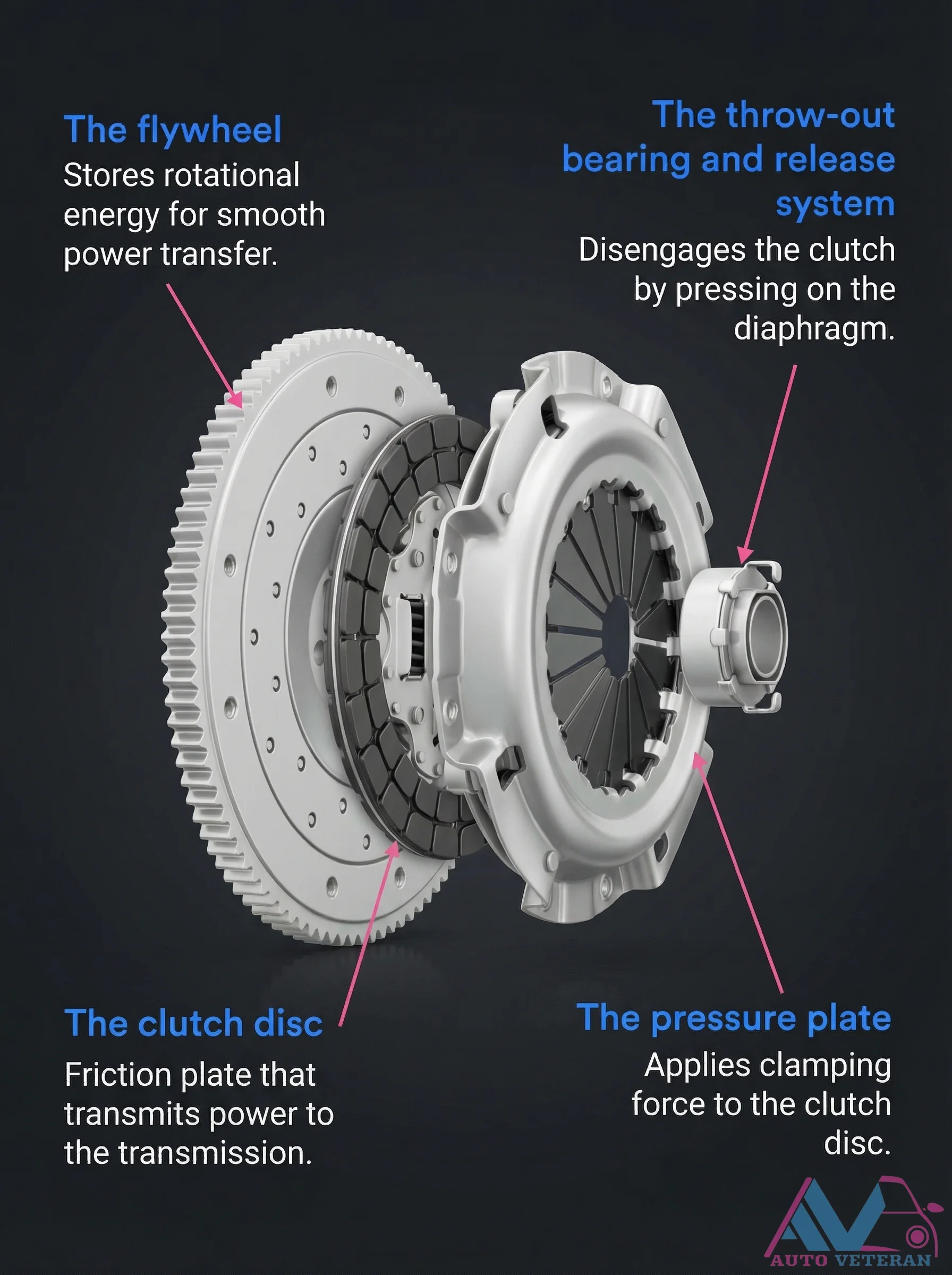
Clutch System Components and Functions Diagram
This diagram illustrates the key components of a manual transmission clutch system and their specific functions. The flywheel stores rotational energy for smooth power transfer, while the clutch disc serves as the friction plate that transmits power to the transmission. The pressure plate applies clamping force to secure the clutch disc, and the throw-out bearing with release system disengages the clutch by pressing on the diaphragm spring. Understanding how these components work together is essential for diagnosing clutch issues and performing proper maintenance.
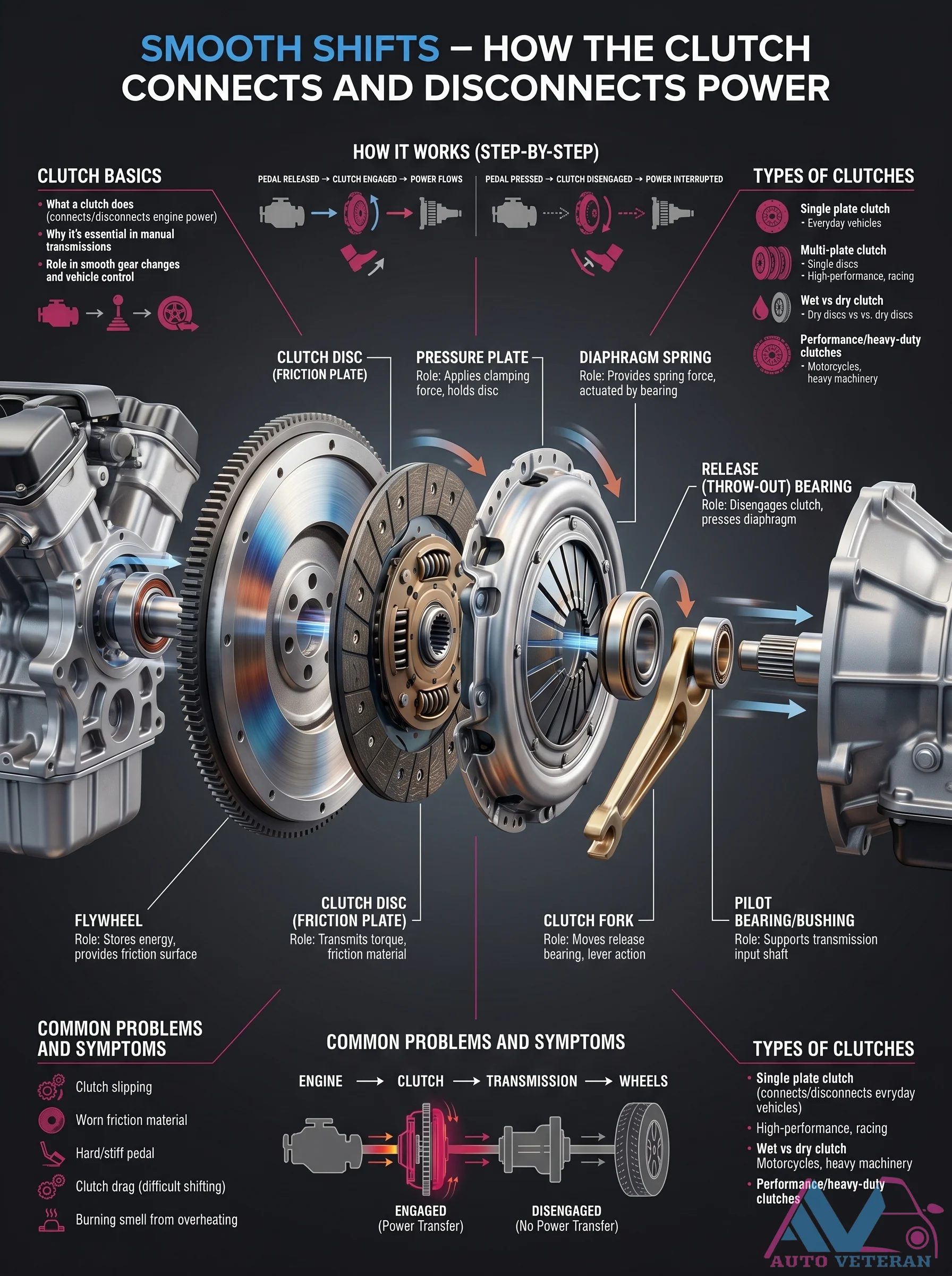
Clutch System Parts and Diagram
This detailed manual transmission clutch diagram breaks down every component from the flywheel and clutch disc to the pressure plate, diaphragm spring, release bearing, and pilot bearing, showing how they work together during engagement and disengagement to deliver smooth gear shifts and power transfer.
Clutch System Working Principle, Types, and Common Problems
Understanding the clutch system begins with its fundamental working principle: when the pedal is released, power flows from the engine to the transmission, engaging the clutch; when pressed, power is interrupted, disengaging it. This system is crucial for smooth gear changes and power control in manual vehicles. Various clutch types serve different needs, including the single plate clutch, common in cars for its simplicity and reliability, and the multi plate clutch, which offers higher torque capacity for performance vehicles. The distinction between wet and dry clutches is also key, with wet clutches using oil for cooling and dry ones relying on air. Performance clutches feature upgraded materials for extreme conditions and faster engagement. Common problems include clutch slipping, characterized by worn friction material and decreased acceleration; clutch drag, which causes difficulty shifting gears due to incomplete disengagement; a hard or stiff clutch pedal, often from hydraulic system or mechanical linkage issues; and a burning smell, indicating overheating and excessive friction material wear. Recognizing these symptoms helps in timely maintenance and ensures optimal vehicle performance.
Coil-on-Plug Ignition System Components and Operation
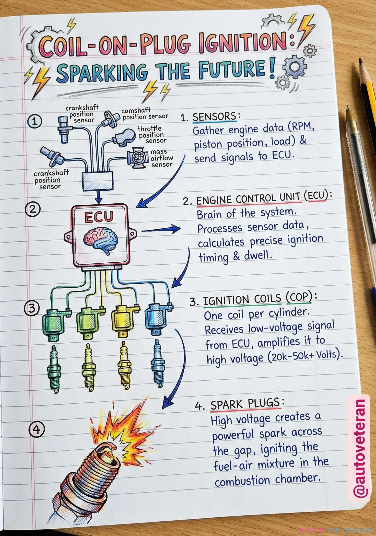
Modern coil-on-plug ignition systems represent a significant advancement in engine technology, where each cylinder receives its own dedicated ignition coil mounted directly on the spark plug. This system relies on precise sensor data from the crankshaft position sensor, camshaft position sensor, throttle position sensor, and mass airflow sensor to feed information to the Engine Control Unit. The ECU processes this real-time engine data including RPM, load, and position to calculate optimal ignition timing and dwell. Each coil then receives a low-voltage signal from the ECU and amplifies it to between 20,000 and 50,000 volts, creating a powerful spark across the spark plug gap that ignites the air-fuel mixture in the combustion chamber. This direct coil-on-plug design eliminates traditional spark plug wires, reduces electrical losses, and allows for more precise spark timing control, resulting in improved combustion efficiency, better fuel economy, and reduced emissions.
Common Check Engine Light Causes
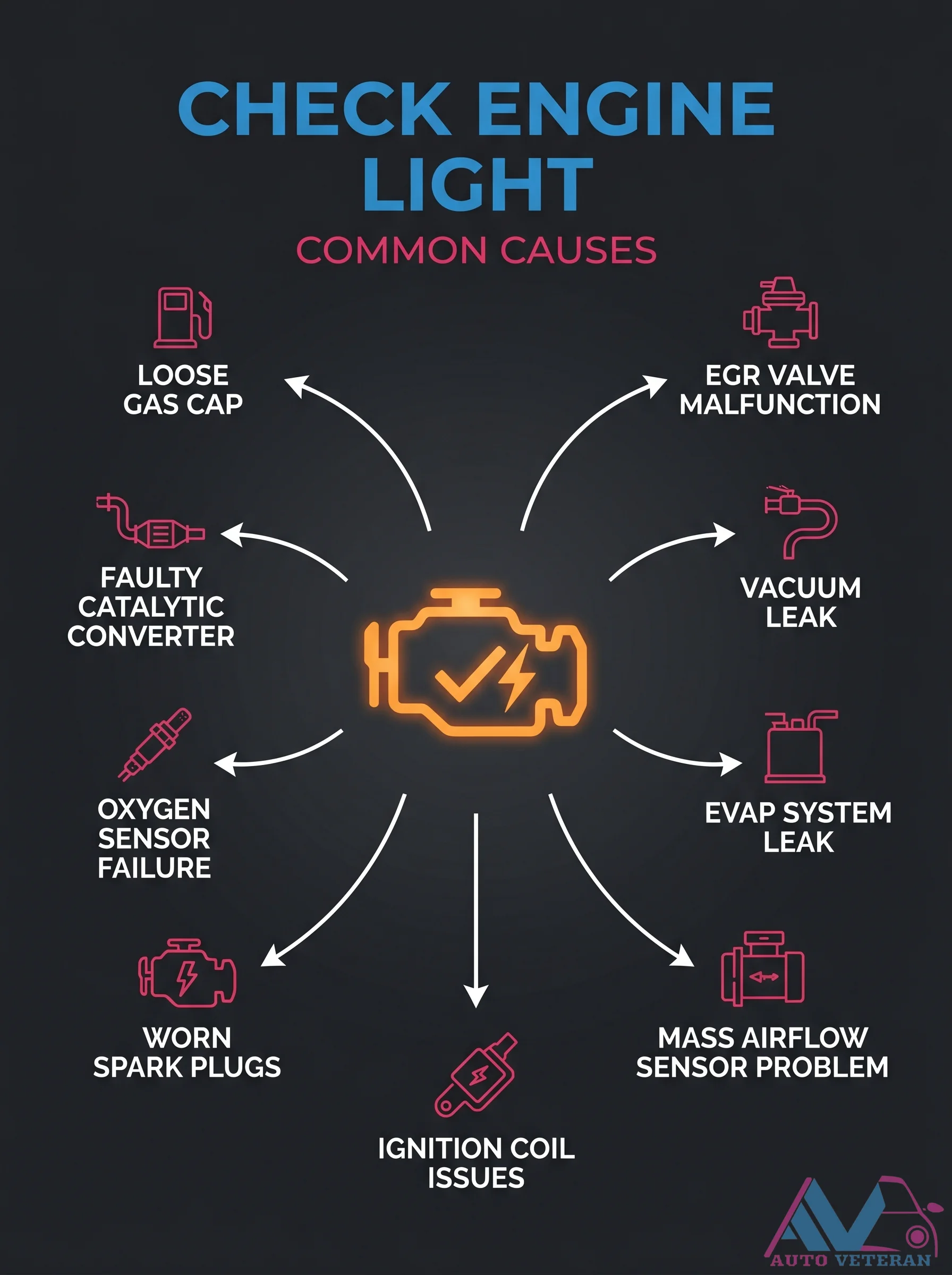
Your check engine light can illuminate for numerous reasons including a loose gas cap, faulty EGR valve, vacuum leak, catalytic converter failure, oxygen sensor malfunction, evaporative system leak, worn spark plugs, ignition coil issues, or a problematic mass airflow sensor. Identifying the specific cause through diagnostic scanning is crucial to prevent further engine damage and ensure optimal performance.
Coolant Temperature Warning Light Causes and Driver Response
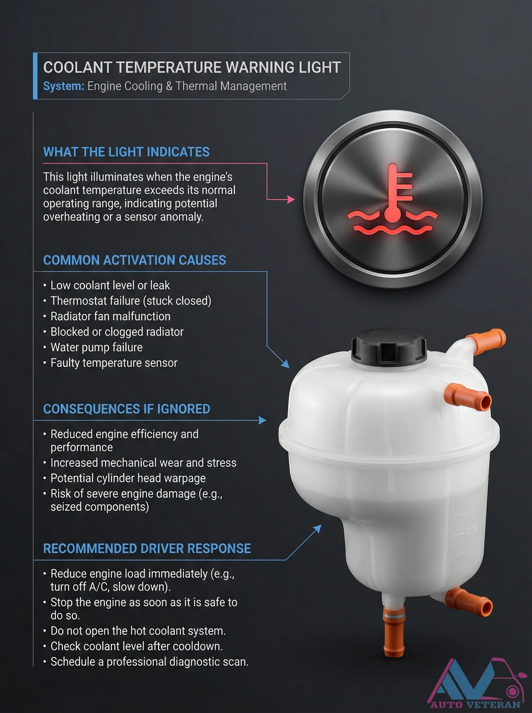
When the coolant temperature warning light activates on your dashboard, it signals that engine coolant has exceeded normal operating parameters, potentially due to low coolant levels, thermostat failure, radiator fan malfunction, clogged radiator, water pump issues, or faulty temperature sensors. Ignoring this warning can lead to reduced engine efficiency, increased mechanical wear, cylinder head warpage, and severe engine damage including seized components. The recommended driver response involves immediately reducing engine load by turning off air conditioning and slowing down, stopping the engine when safe, avoiding opening the hot coolant system, checking coolant levels after cooldown, and scheduling professional diagnostic scanning.
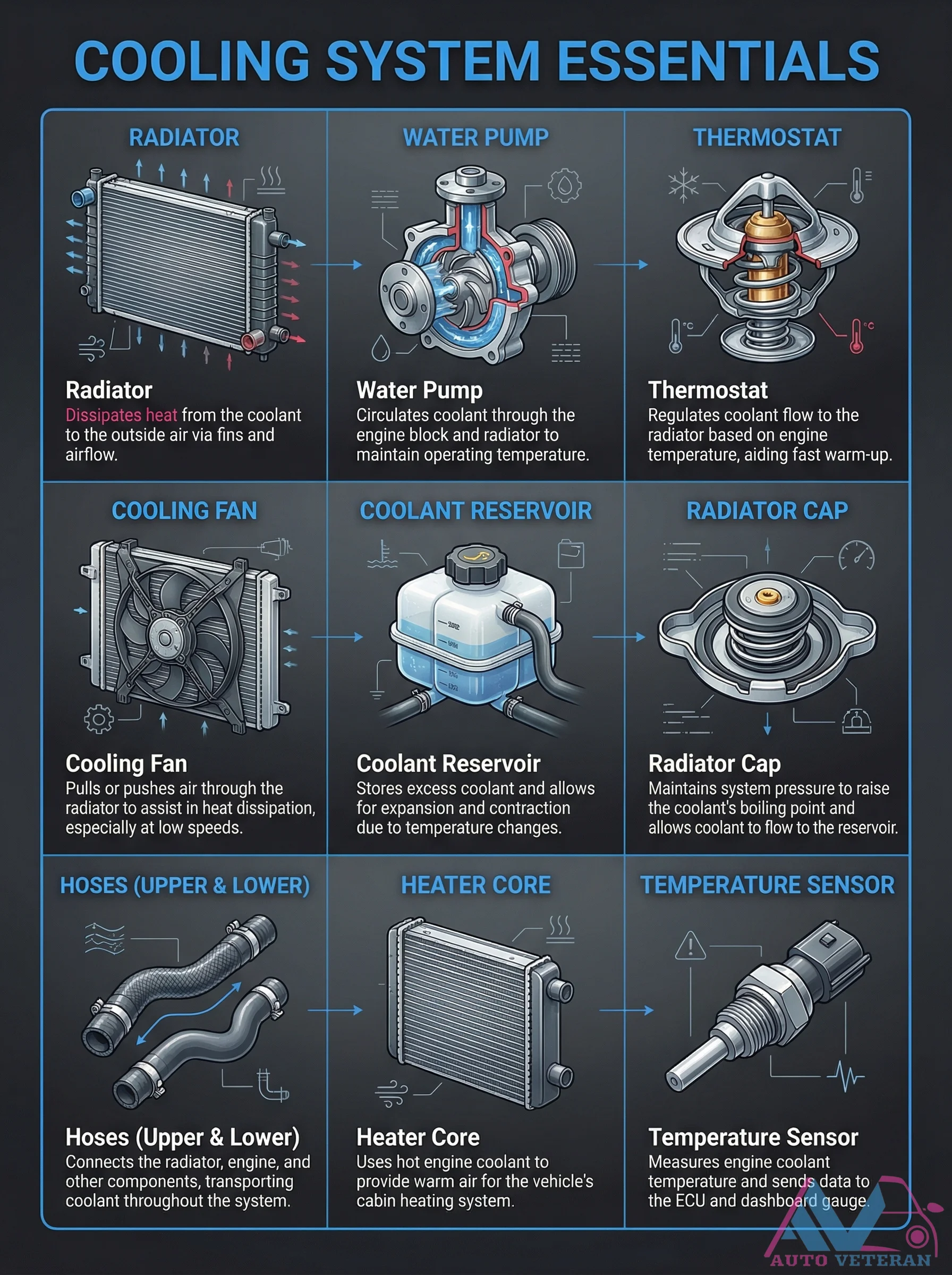
Cooling System Components and Functions Diagram
This comprehensive diagram illustrates the essential components of an automotive cooling system and their specific functions. The radiator dissipates heat from coolant to outside air via fins and airflow, while the water pump circulates coolant through the engine block and radiator to maintain operating temperature. The thermostat regulates coolant flow to the radiator based on engine temperature, aiding fast warm up. Additional components include the cooling fan that pulls or pushes air through the radiator, especially at low speeds, the coolant reservoir that stores excess coolant for expansion and contraction, and the radiator cap that maintains system pressure to raise the coolant boiling point. The system also features upper and lower hoses connecting components, a heater core that uses hot coolant for cabin heating, and a temperature sensor that measures coolant temperature for the ECU and dashboard gauge.
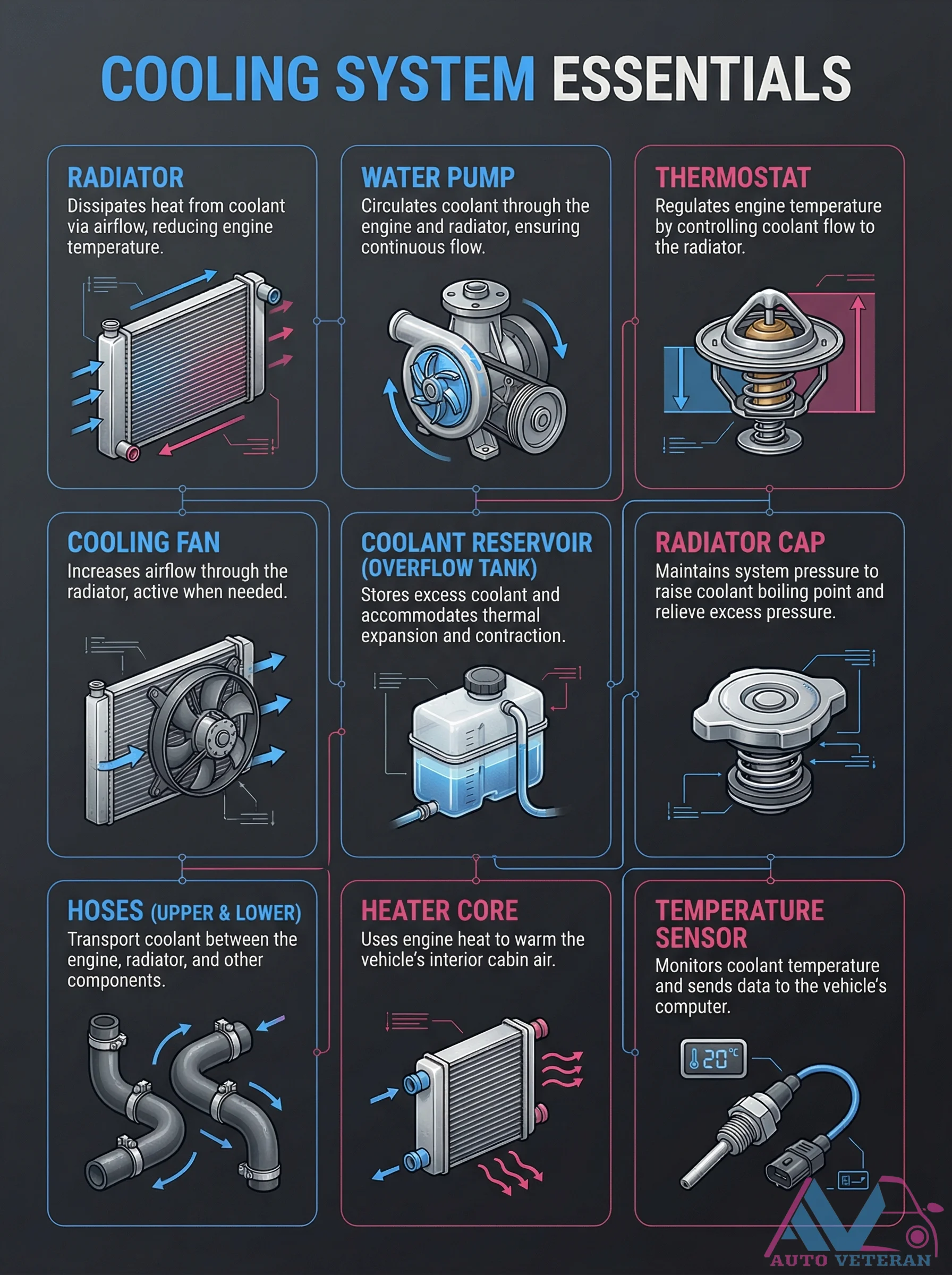
Cooling System Essentials Diagram with Components
This comprehensive diagram illustrates the essential components of an automotive cooling system, including the radiator, water pump, thermostat, cooling fan, coolant reservoir, radiator cap, hoses, heater core, and temperature sensor. Each component is clearly labeled with its specific function, such as dissipating heat from coolant, circulating coolant through the engine and radiator, regulating engine temperature, increasing airflow through the radiator, storing excess coolant, maintaining system pressure, transporting coolant between components, warming the vehicle's interior cabin air, and monitoring coolant temperature for the vehicle's computer.