Interactive Explorer
ECM Function Common Failures and Maintenance
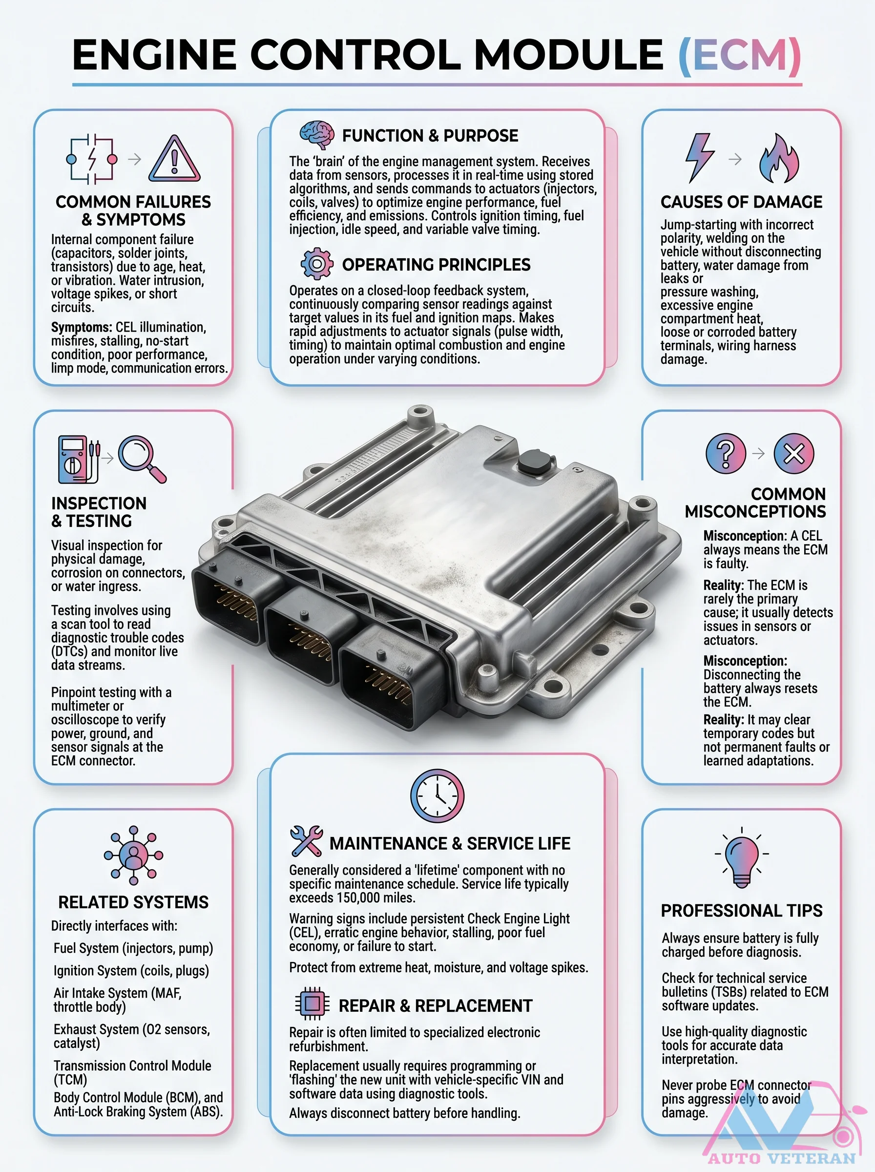
The Engine Control Module acts as the brain of the engine system; receiving sensor data and processing it in real time to control ignition timing; fuel injection; idle speed and variable valve timing. Common failures include water ingress; voltage spikes from incorrect jump starting or welding; and internal component degradation. Symptoms range from check engine light illumination and misfires to stalling; no start conditions and limp mode. Maintenance involves ensuring a fully charged battery; protecting from heat and moisture; and checking for technical service bulletins related to software updates. Testing requires a scan tool for diagnostic trouble codes and live data; plus an oscilloscope for pinpoint testing at the ECM connector. Contrary to misconception; the ECM is rarely the primary cause of issues; it usually detects sensor or actuator problems. Disconnecting the battery only clears temporary codes; not permanent faults or learned adaptations. The ECM interfaces with fuel; air intake; exhaust; transmission; body control and ABS systems.
ECU Input Sensors and Output Actuator Diagram
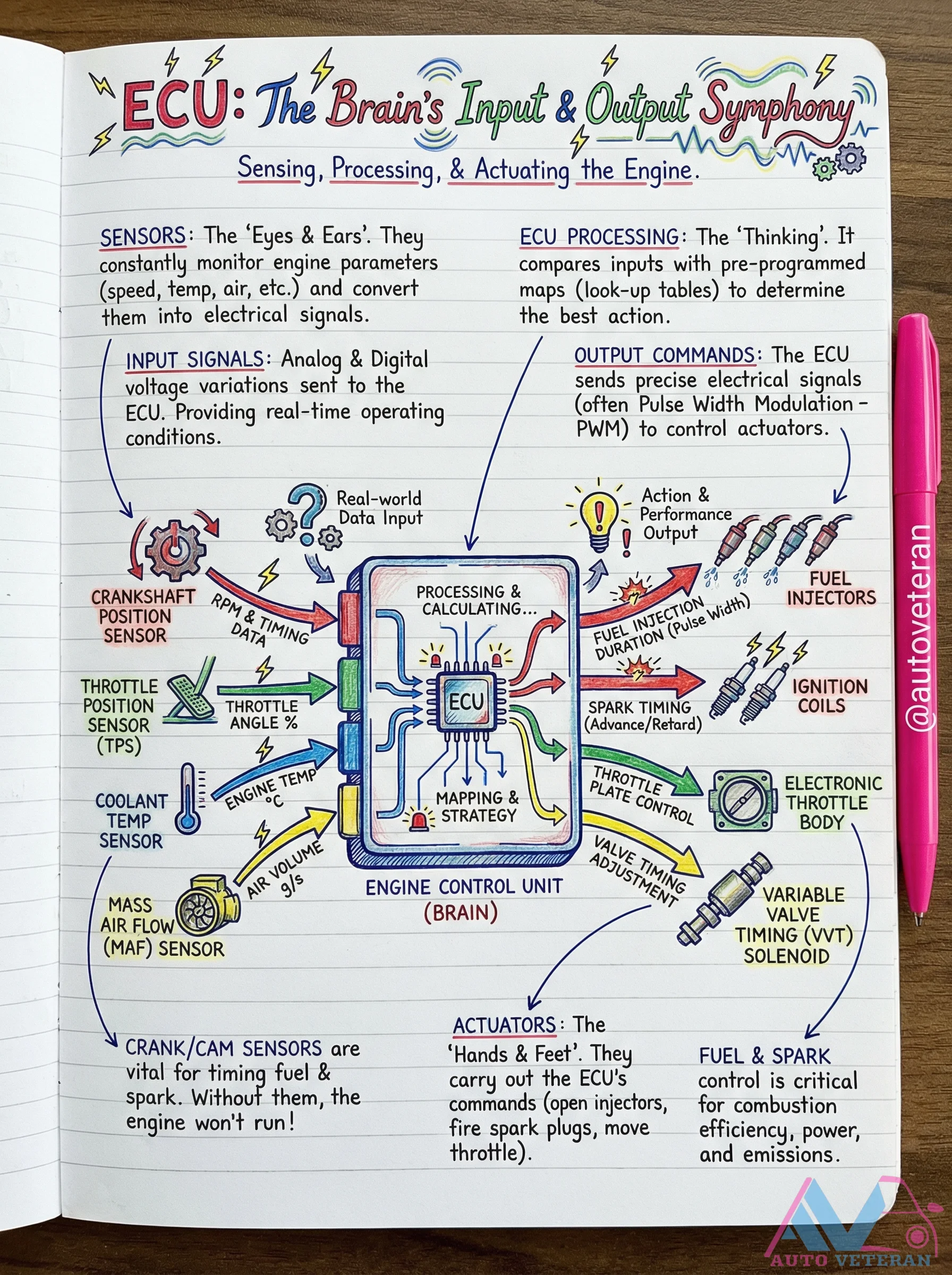
The Engine Control Unit functions as the central processing brain of modern vehicles, constantly monitoring real-time operating conditions through a network of input sensors. These sensors, including the Mass Airflow Sensor, Crankshaft Position Sensor, Throttle Position Sensor, and Coolant Temperature Sensor, provide critical data on parameters like air volume, engine speed, throttle angle, and temperature. The ECU processes this information by comparing it against pre-programmed maps and lookup tables, then calculates optimal responses. It sends precise output commands using Pulse Width Modulation to control actuators such as fuel injectors, ignition coils, throttle bodies, and Variable Valve Timing solenoids. This coordinated system ensures accurate fuel injection timing, spark advance or retard, and throttle plate adjustment for optimal combustion efficiency, power delivery, and emissions control.
ECU Inputs and Outputs Diagram
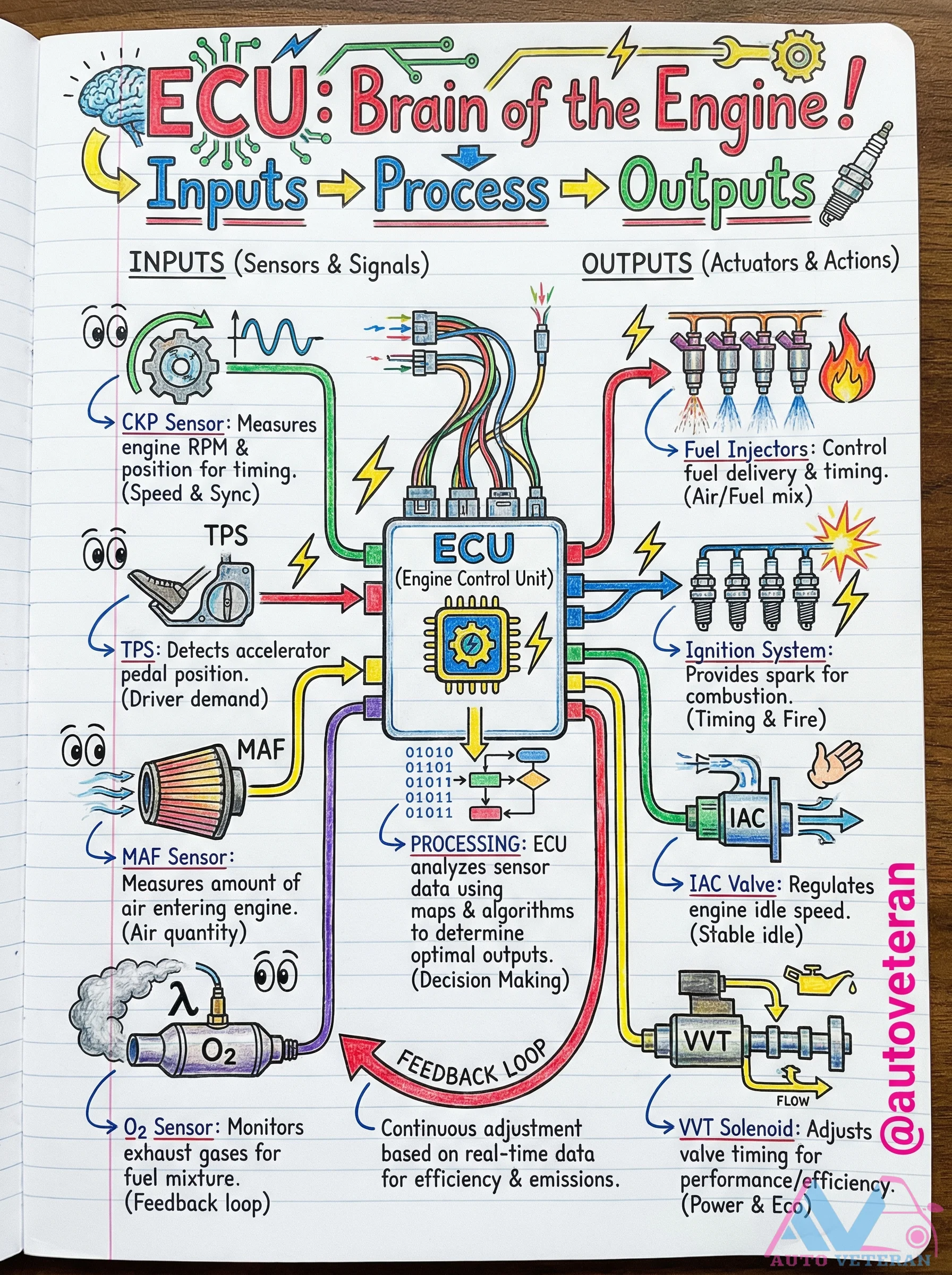
The Engine Control Unit functions as the central processing hub of your vehicle, continuously analyzing sensor inputs like CKP, TPS, MAF, and O2 data to calculate optimal outputs including fuel injection timing, ignition spark, idle speed control via the IAC valve, and variable valve timing adjustments through the VVT solenoid. This real-time feedback loop ensures precise air/fuel mixture, stable engine operation, and balanced performance with emissions efficiency.
EGR Valve Ported Vacuum Control Operation
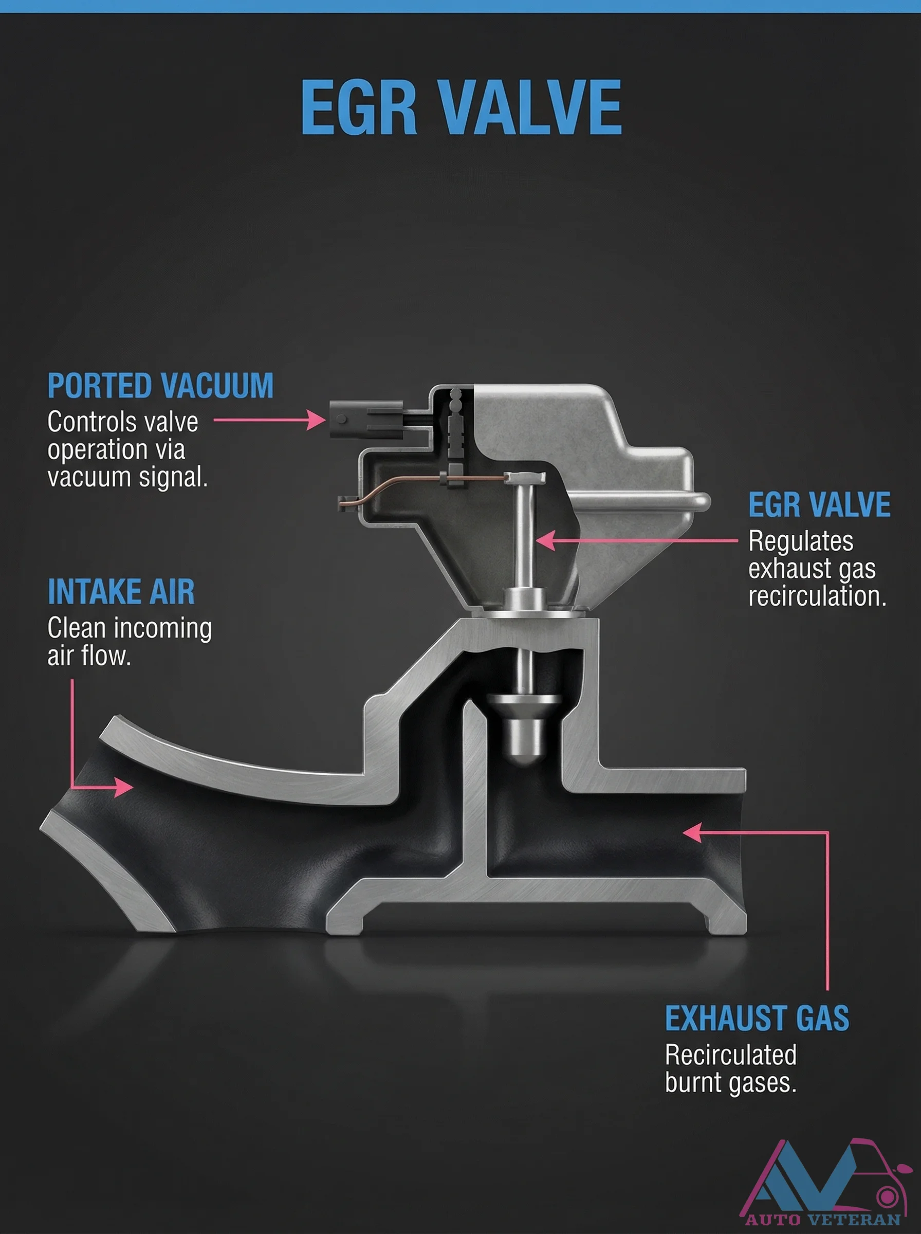
The EGR valve's ported vacuum system precisely controls valve operation through a vacuum signal, regulating exhaust gas recirculation into the intake air stream. This mechanism manages the flow of clean incoming air mixed with recirculated burnt gases to optimize combustion efficiency and reduce emissions.
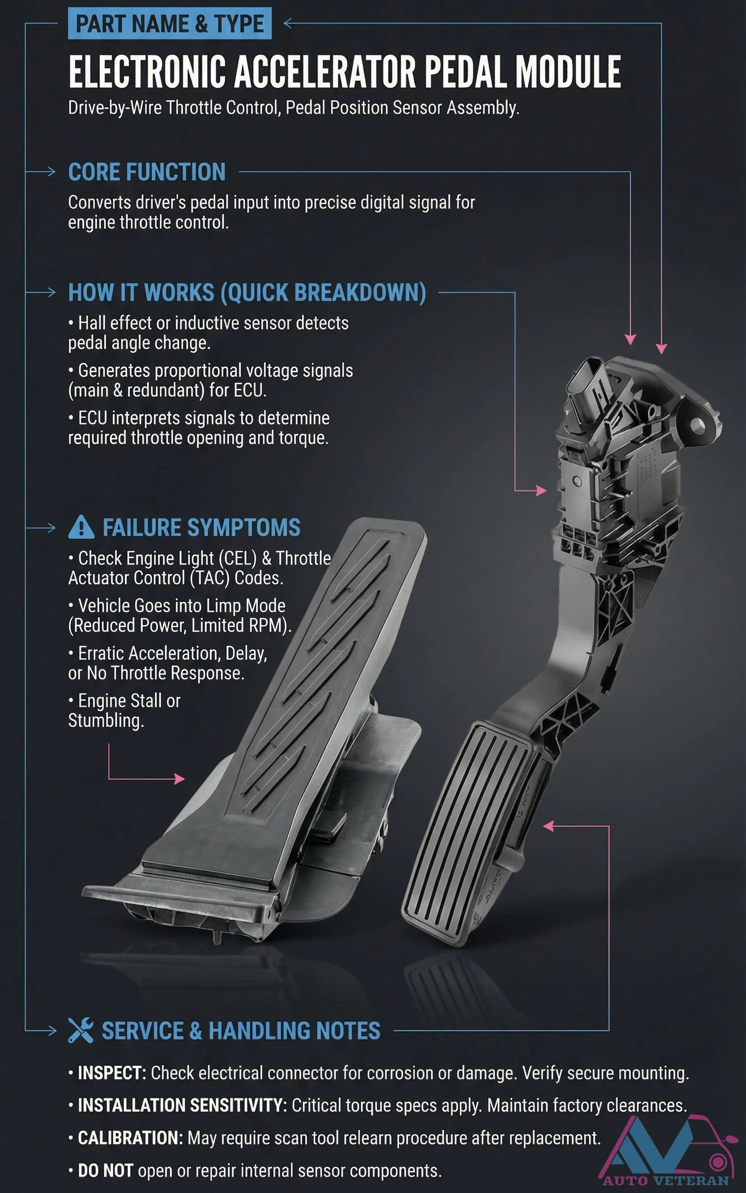
Electronic Accelerator Pedal Module Failure Symptoms
When the electronic accelerator pedal module fails, drivers experience critical symptoms including a check engine light with throttle actuator control codes, limp mode with reduced power and limited RPM, erratic acceleration or delayed throttle response, and potential engine stalling or stumbling. This drive by wire throttle control system uses Hall effect or inductive sensors to convert pedal position into precise digital signals for the ECU, with installation requiring careful attention to torque specifications and clearance requirements, plus potential scan tool calibration after replacement.
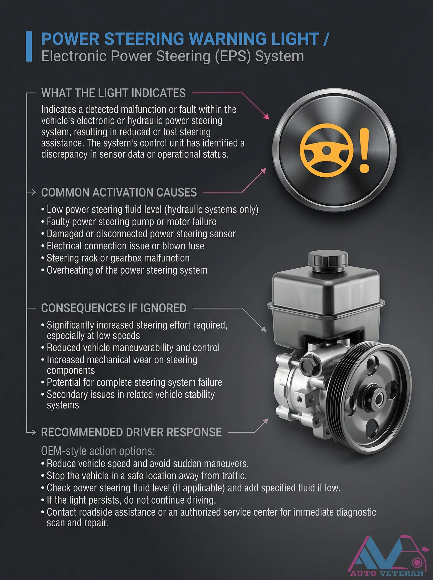
Electronic Power Steering Warning Light Activation Causes
When the POWER STEERING warning light illuminates on your dashboard, it signals that the vehicle's Electronic Power Steering system has detected a critical malfunction. This alert indicates reduced or lost steering assistance due to issues ranging from low fluid levels in hydraulic systems to faulty pumps, sensor failures, electrical problems, or overheating. Ignoring this warning can lead to significantly increased steering effort, reduced maneuverability, accelerated component wear, and potential complete system failure. Immediate driver response should include reducing speed, avoiding sudden maneuvers, checking fluid levels if applicable, and seeking professional diagnostic scanning and repair to restore safe steering operation.
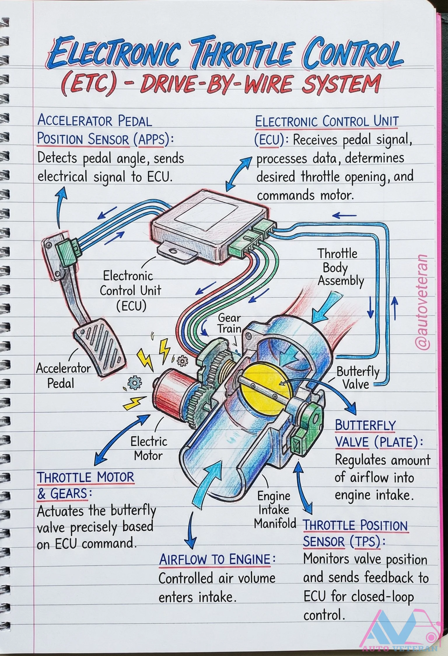
Electronic Throttle Control Drive-By-Wire System Components
The drive-by-wire system replaces mechanical throttle linkages with electronic components for precise engine control. An accelerator pedal position sensor detects pedal angle and sends an electrical signal to the electronic control unit, which processes this data to determine the desired throttle opening. The ECU then commands an electric motor in the throttle body assembly, which actuates the butterfly valve through a gear train to regulate airflow into the engine intake manifold. A throttle position sensor monitors the valve's position and provides feedback to the ECU for closed-loop control, ensuring accurate air volume delivery to the engine based on driver input.
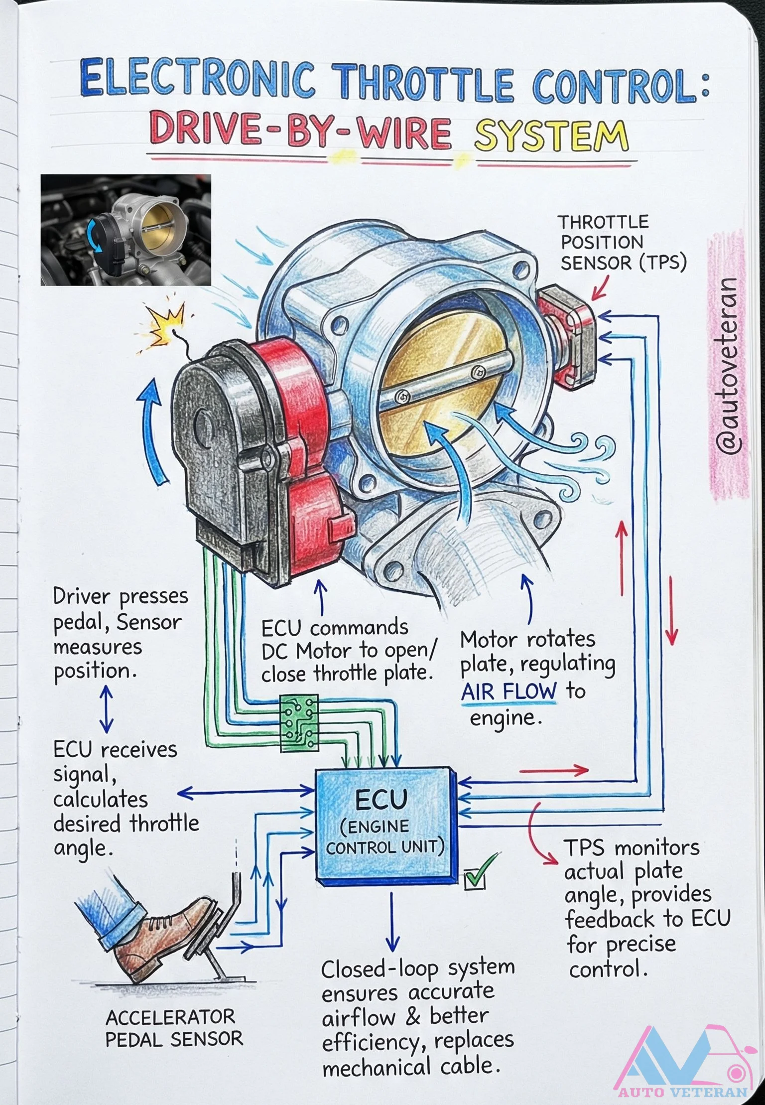
Electronic Throttle Control Drive-by-Wire System Operation
The electronic throttle control system, also known as drive-by-wire, replaces traditional mechanical cables with an intelligent network of sensors and actuators. When the driver presses the accelerator pedal, the pedal sensor sends a signal to the Engine Control Unit, which calculates the desired throttle angle and commands a DC motor to rotate the throttle plate accordingly. The Throttle Position Sensor continuously monitors the actual plate position, providing real-time feedback to the ECU for precise closed-loop control. This sophisticated system ensures accurate airflow regulation, improved engine efficiency, and seamless throttle response without physical cable connections.
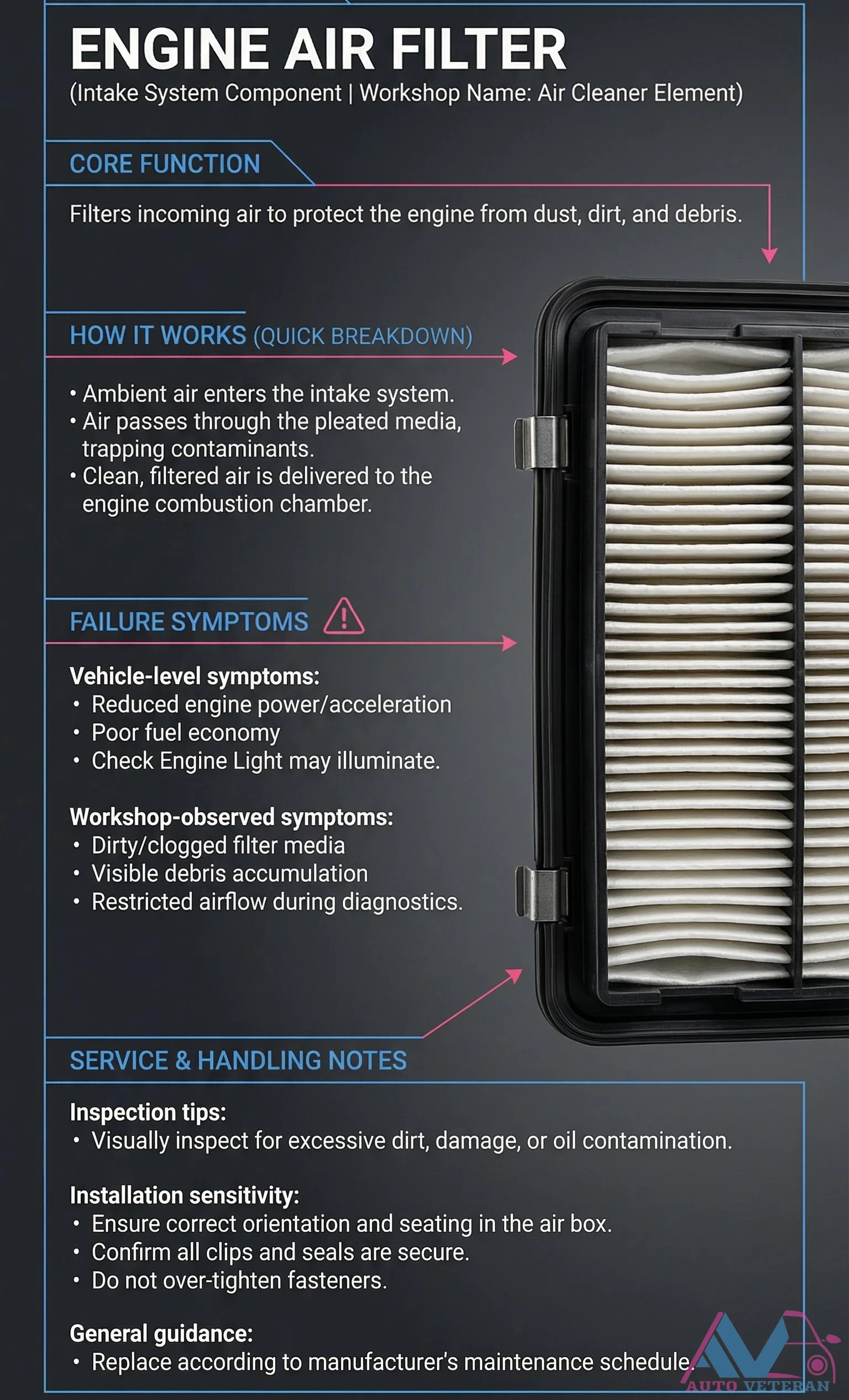
Engine Air Filter Failure Symptoms and Inspection Tips
A clogged or contaminated engine air filter restricts airflow to the combustion chamber, causing noticeable vehicle level issues like reduced power, poor acceleration, and decreased fuel economy. During workshop diagnostics, technicians look for visible debris accumulation, oil contamination on the filter media, and measurable airflow restriction. Proper installation requires correct orientation in the air box, secure clips and seals, and avoiding over tightened fasteners to maintain optimal engine performance.
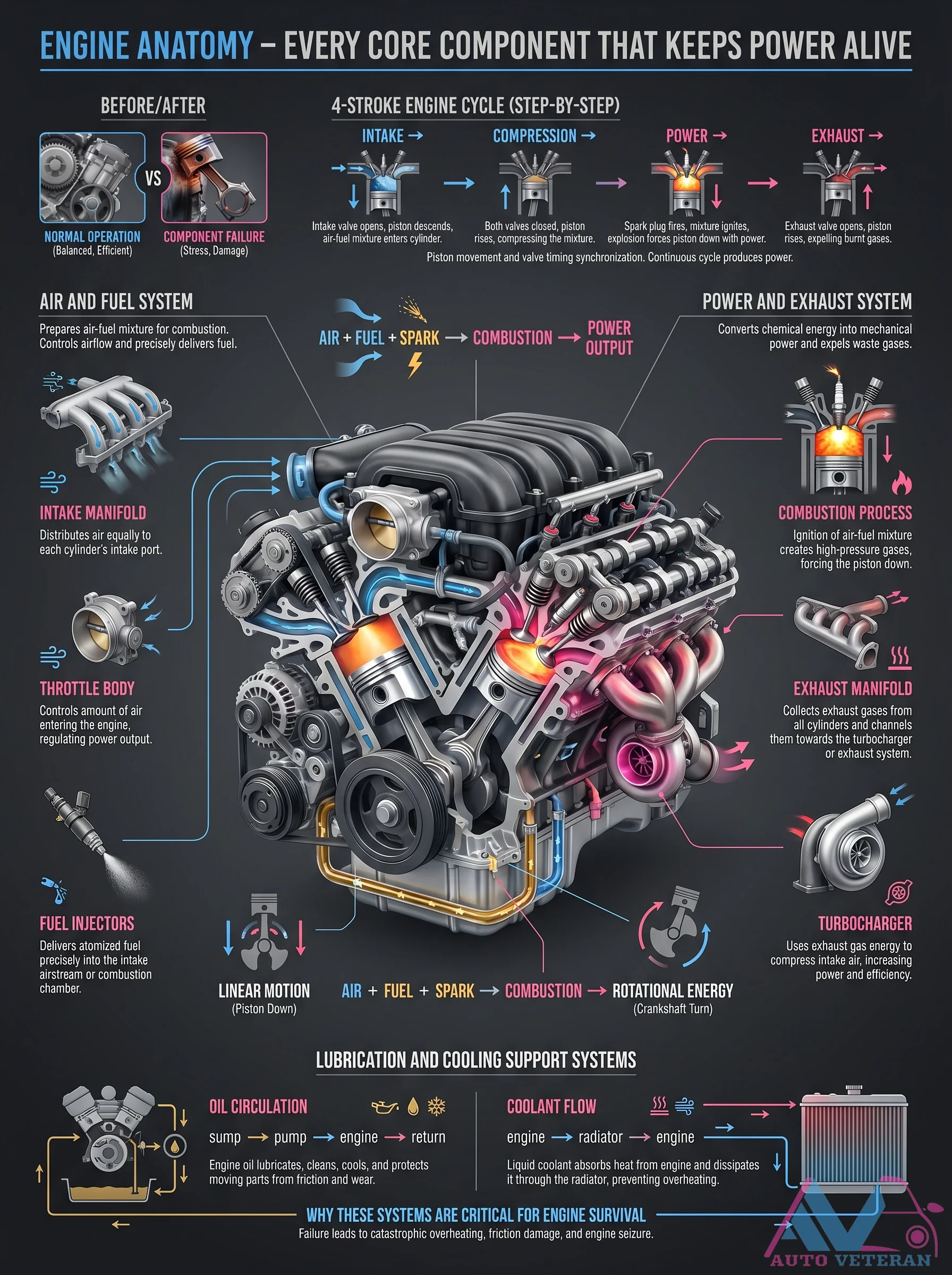
Engine Anatomy Core Components
This detailed diagram breaks down the 4 stroke engine cycle (intake, compression, power, exhaust) and labels every core component that keeps power alive; from the air and fuel system preparing the mixture, to the combustion process converting chemical energy into mechanical output, and the power and exhaust system expelling waste gases. It also highlights the critical lubrication and cooling support systems; noting how oil circulation lubricates, cleans, and protects while coolant absorbs and dissipates heat. The illustration emphasizes why these systems are critical for engine survival; failure leads to catastrophic overheating, friction damage, and engine seizure.
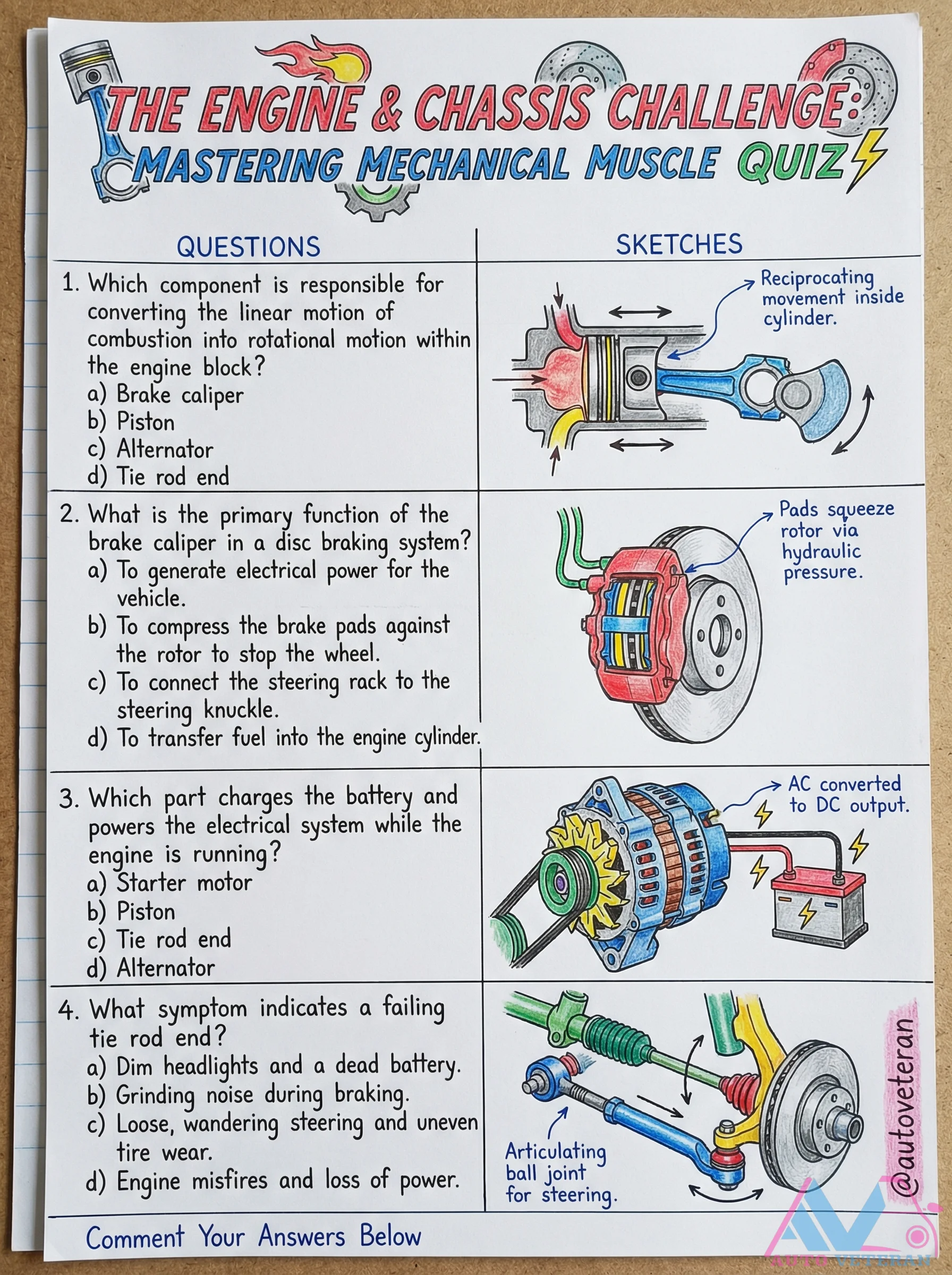
Engine and Chassis Quiz Questions on Piston and Brake
This quiz tests your knowledge of key automotive components, focusing on the piston's role in converting combustion into rotational motion and the brake caliper's function in squeezing pads against the rotor via hydraulic pressure. It also covers symptoms of failing tie rod ends, such as grinding noises and uneven tire wear, and identifies the alternator as the component that charges the battery and powers electrical systems. Answer these questions to master the mechanical muscle of your vehicle.
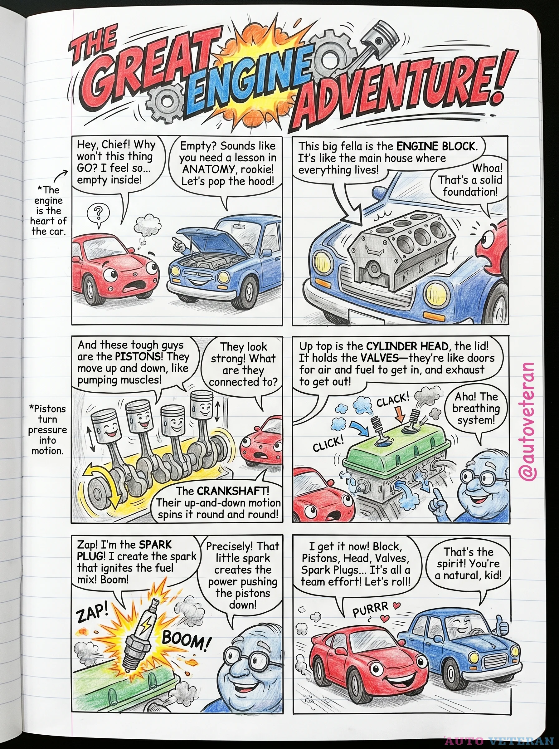
Engine Block Anatomy with Pistons, Valves, and Crankshaft
The engine block serves as the main housing where all critical components work together; the cylinder head acts as the lid holding valves that regulate air and fuel intake and exhaust flow; pistons move up and down within the block, connected to the crankshaft which converts their motion into rotational power; spark plugs ignite the fuel mixture to create the combustion that drives the pistons, making it a coordinated team effort for engine operation.
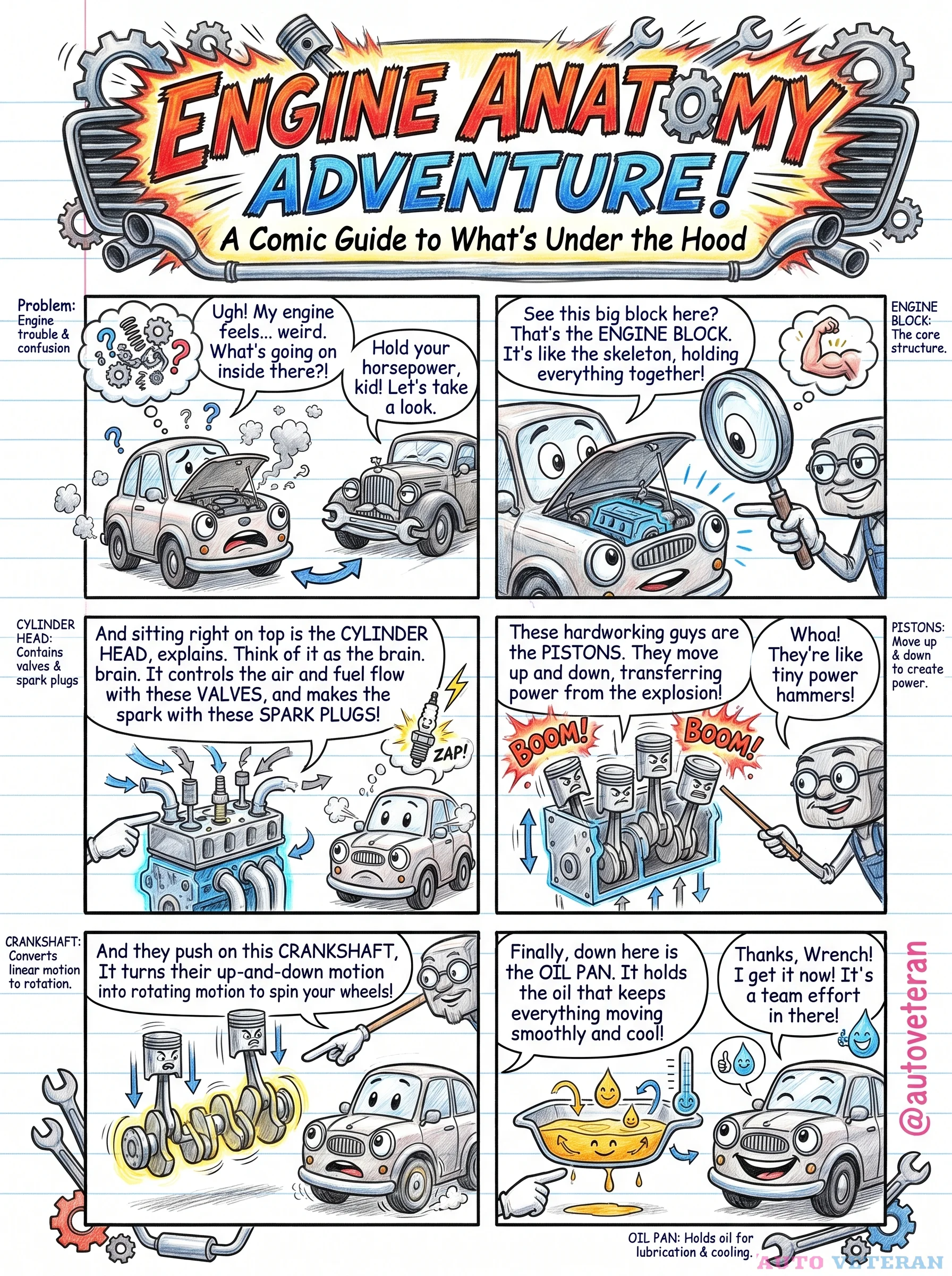
Engine Block, Pistons, Crankshaft, and Oil Pan
The engine block serves as the core structure, holding all components together like a skeleton. Inside, pistons move up and down, transferring power from combustion to the crankshaft, which converts linear motion into rotation to spin the wheels. Below, the oil pan holds lubrication oil to keep everything running smoothly.
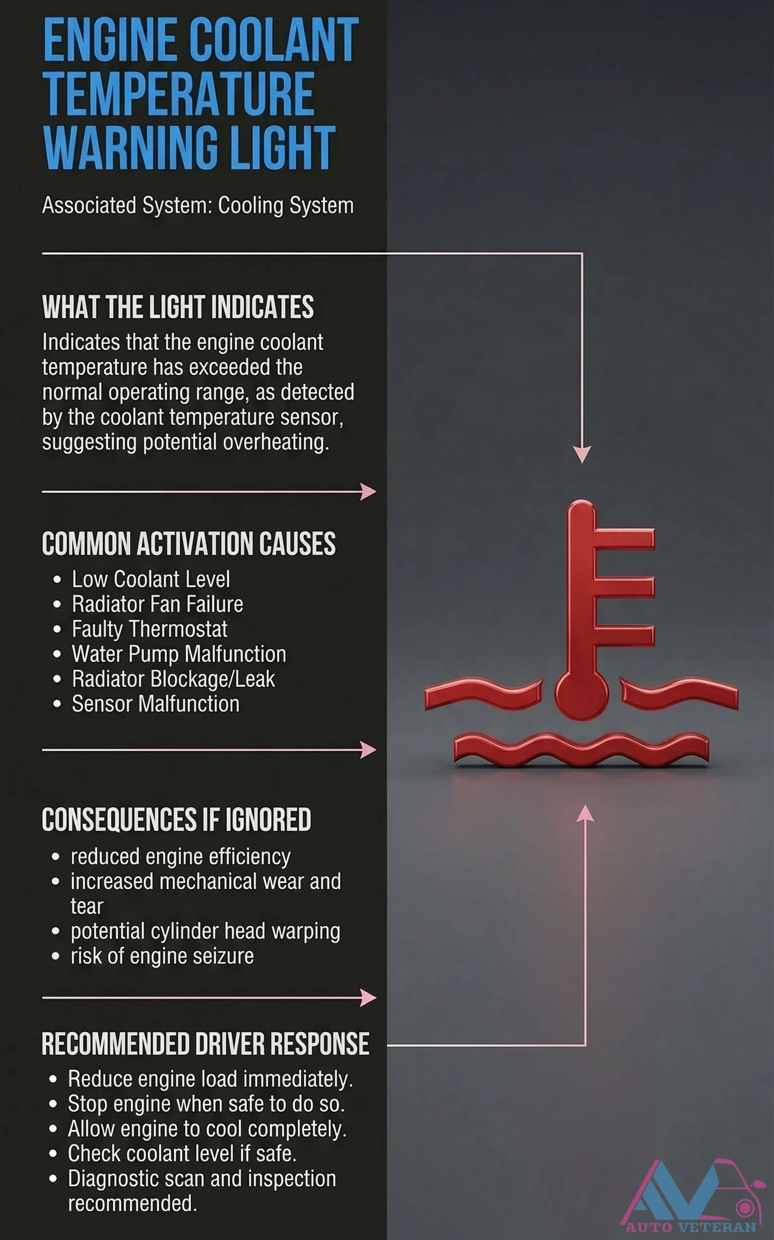
Engine Coolant Temperature Warning Light Activation
The engine coolant temperature warning light illuminates when the coolant temperature sensor detects temperatures exceeding the normal operating range, signaling potential overheating. Common causes include low coolant levels, radiator cap issues, water pump malfunctions, radiator blockages or leaks, and sensor failures. Ignoring this warning can lead to reduced engine efficiency, increased mechanical wear, cylinder head warping, and even engine seizure. Recommended driver responses include immediately reducing engine load, safely stopping the engine, allowing it to cool completely, checking coolant levels if safe, and performing diagnostic scans and inspections to address the underlying issue.
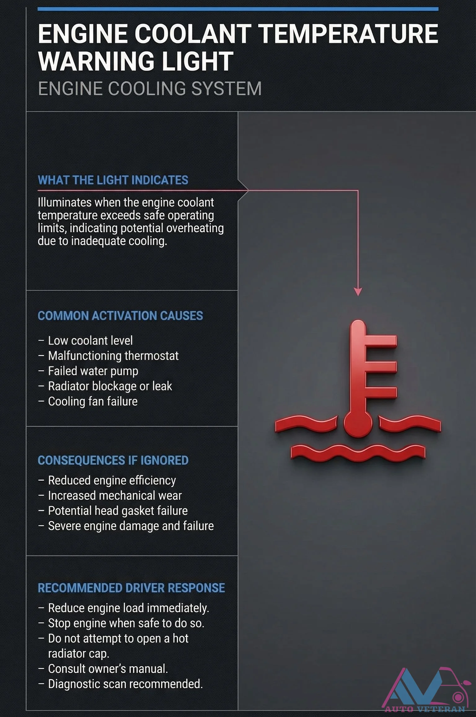
Engine Coolant Temperature Warning Light Activation Causes
The engine coolant temperature warning light illuminates when coolant temperature exceeds safe operating limits, signaling potential overheating from inadequate cooling. Common activation triggers include low coolant levels, malfunctioning thermostats, radiator blockages or leaks, and cooling fan failures. Ignoring this warning leads to reduced engine efficiency, increased mechanical wear, potential head gasket failure, and severe engine damage. Recommended driver response involves immediately reducing engine load, stopping the engine when safe, avoiding opening hot radiator caps, consulting the owner's manual, and performing diagnostic scans.
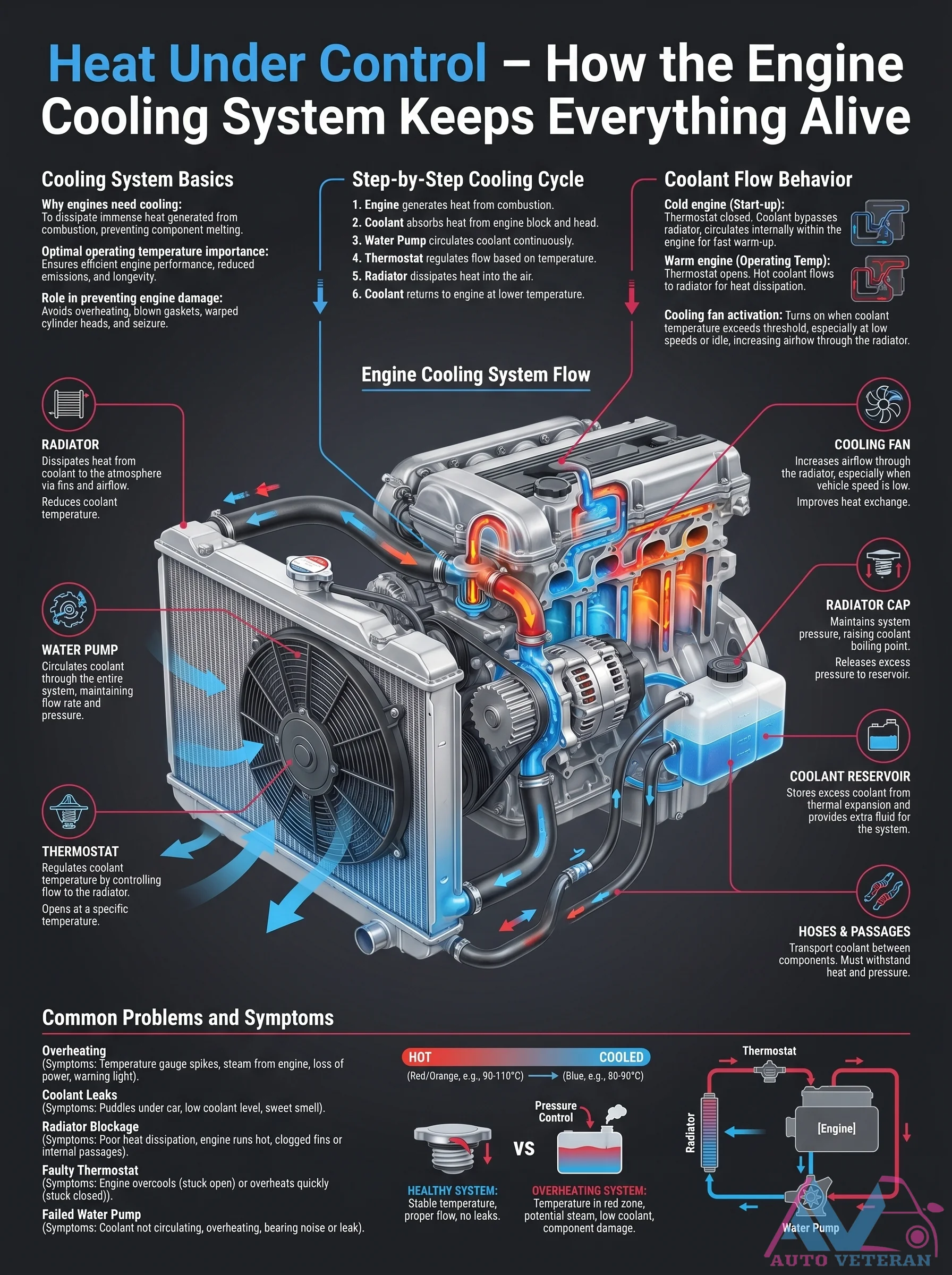
Engine Cooling System Flow Cycle
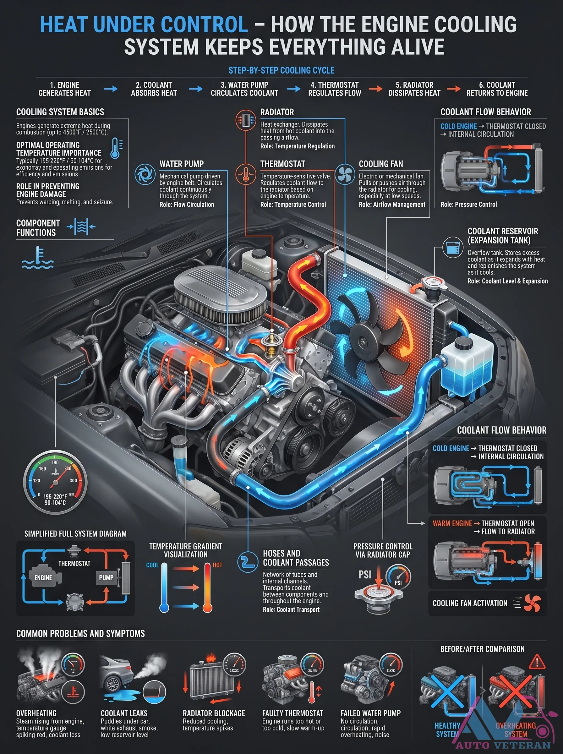
The step by step cooling cycle ensures your engine maintains the perfect operating temperature. At cold start, coolant is trapped in the engine block by a closed thermostat. As the engine warms up, the thermostat opens allowing coolant to flow to the radiator where the cooling fan and radiator cap manage pressure and heat dissipation. This continuous loop keeps the engine from overheating while allowing rapid warm up for efficiency. The water pump drives circulation while hoses and passages direct fluid between components including the coolant reservoir and heater core. Understanding this flow helps diagnose issues like overheating or overcooling caused by a stuck thermostat, failed water pump, or radiator blockage.

Engine Cooling System Step Cycle
This diagram walks through the engine cooling system's step-by-step cycle: engine coolant absorbs heat from combustion, the water pump circulates it, the thermostat regulates flow to maintain optimal operating temperature near 195-220°F, the radiator dissipates heat into the air, and coolant returns to the engine. It also illustrates cold engine internal circulation with thermostat closed versus warm engine flow to the radiator, highlighting the role of the cooling fan, expansion tank, and radiator cap in pressure control and preventing overheating, warping, or seizure.
Engine Cooling System Step-by-Step Cycle
This step-by-step cooling cycle diagram illustrates how the engine cooling system keeps everything alive. Coolant absorbs heat from the engine, circulates via the water pump, gets regulated by the thermostat, dissipates heat in the radiator, and returns to the engine. Key components include the coolant reservoir, hoses, radiator cap, and cooling fan. The system maintains optimal operating temperature around 195 to 220 degrees Fahrenheit to prevent overheating, warping, melting, and seizure. Common problems shown include overheating, coolant leaks, radiator blockage, faulty thermostat, and failed water pump. Symptoms like high temperature gauge, coolant loss, and low reservoir level are highlighted.
Engine Cooling System Thermal Balance and Operation
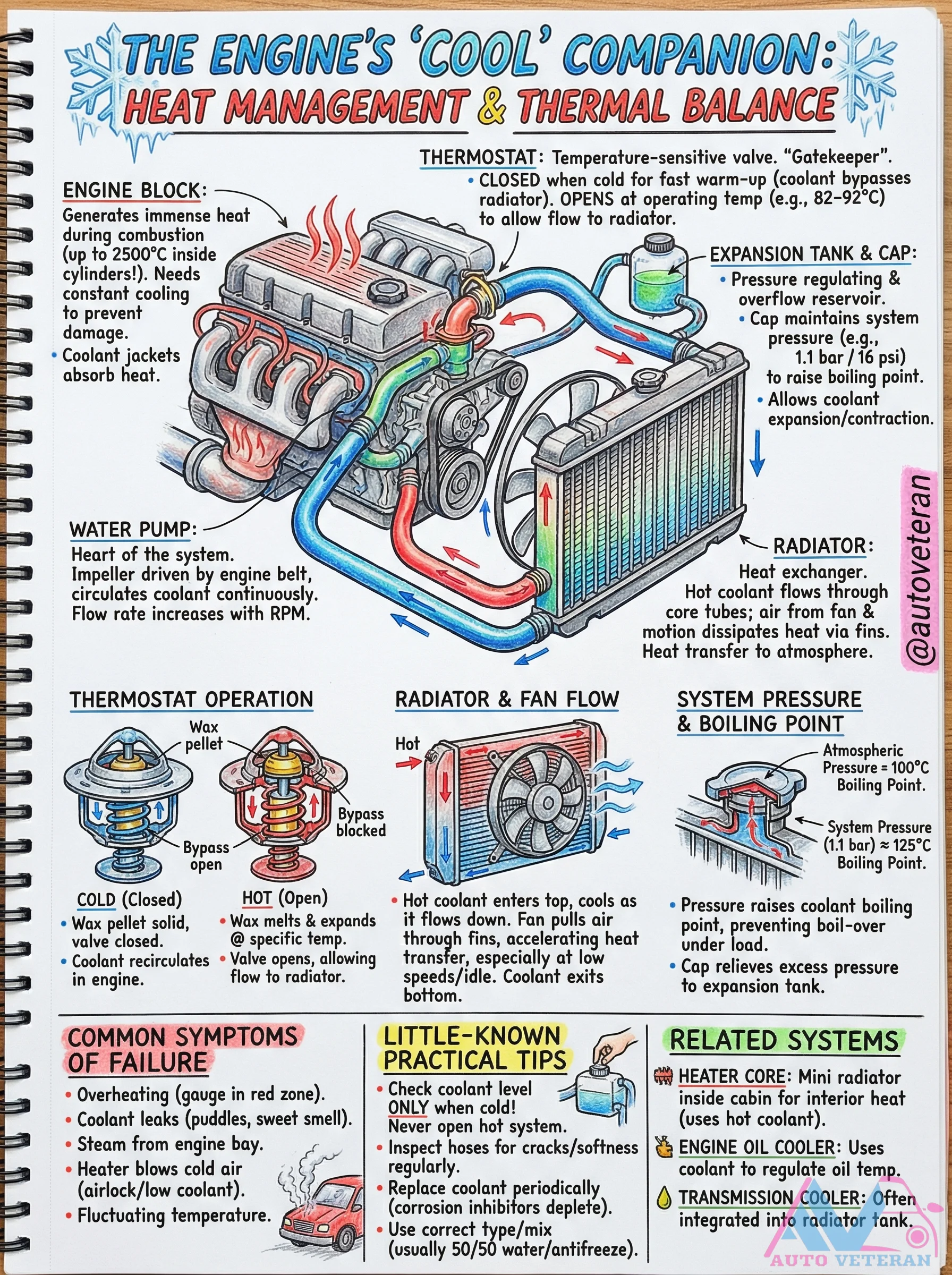
The automotive cooling system maintains precise thermal balance through a coordinated network of components. The thermostat acts as a temperature sensitive gatekeeper, remaining closed during cold starts to accelerate engine warm up, then opening at operating temperature to allow coolant flow to the radiator. Coolant jackets within the engine block absorb immense combustion heat, reaching temperatures up to 2500°C inside cylinders. The water pump circulates coolant throughout the system, with flow rate increasing proportionally with engine RPM. The radiator transfers heat to the atmosphere through its finned core tubes, assisted by the cooling fan which accelerates heat dissipation, particularly at low speeds or idle. System pressure regulation is critical, with the radiator cap maintaining approximately 1.1 bar (16 psi) to raise the coolant boiling point from 100°C to about 125°C, preventing vaporization under load. The expansion tank accommodates coolant expansion and contraction while serving as an overflow reservoir. Related systems including the heater core, engine oil cooler, and transmission cooler integrate with this thermal management network to maintain optimal operating conditions across all vehicle systems.
Engine Core Components Diagram and Functions
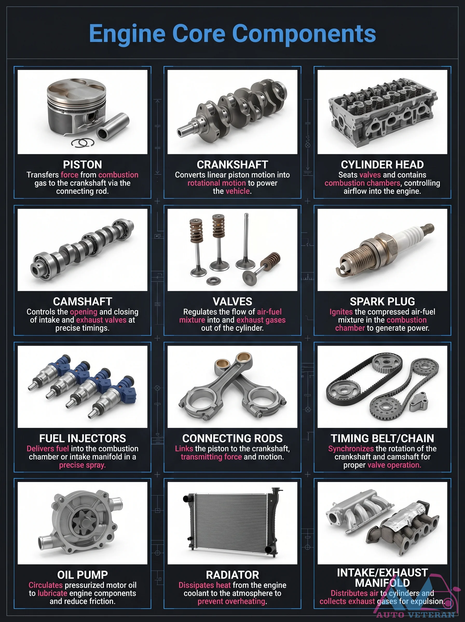
This diagram illustrates the fundamental components that make up an internal combustion engine, detailing their specific roles in power generation. The piston transfers force from combustion to the crankshaft via the connecting rod, while the crankshaft converts linear motion into rotational power. The cylinder head houses valves and combustion chambers, controlling airflow, and the camshaft precisely times valve operation. Valves regulate air fuel mixture flow, spark plugs ignite the mixture, and fuel injectors deliver fuel. Connecting rods link pistons to the crankshaft, the timing belt synchronizes crankshaft and camshaft rotation, the oil pump circulates lubricant, the radiator dissipates heat, and intake exhaust manifolds distribute air and collect gases. Each component works in concert to ensure efficient engine operation.