Interactive Explorer
H4 Headlight Bulb Working Principle and Components
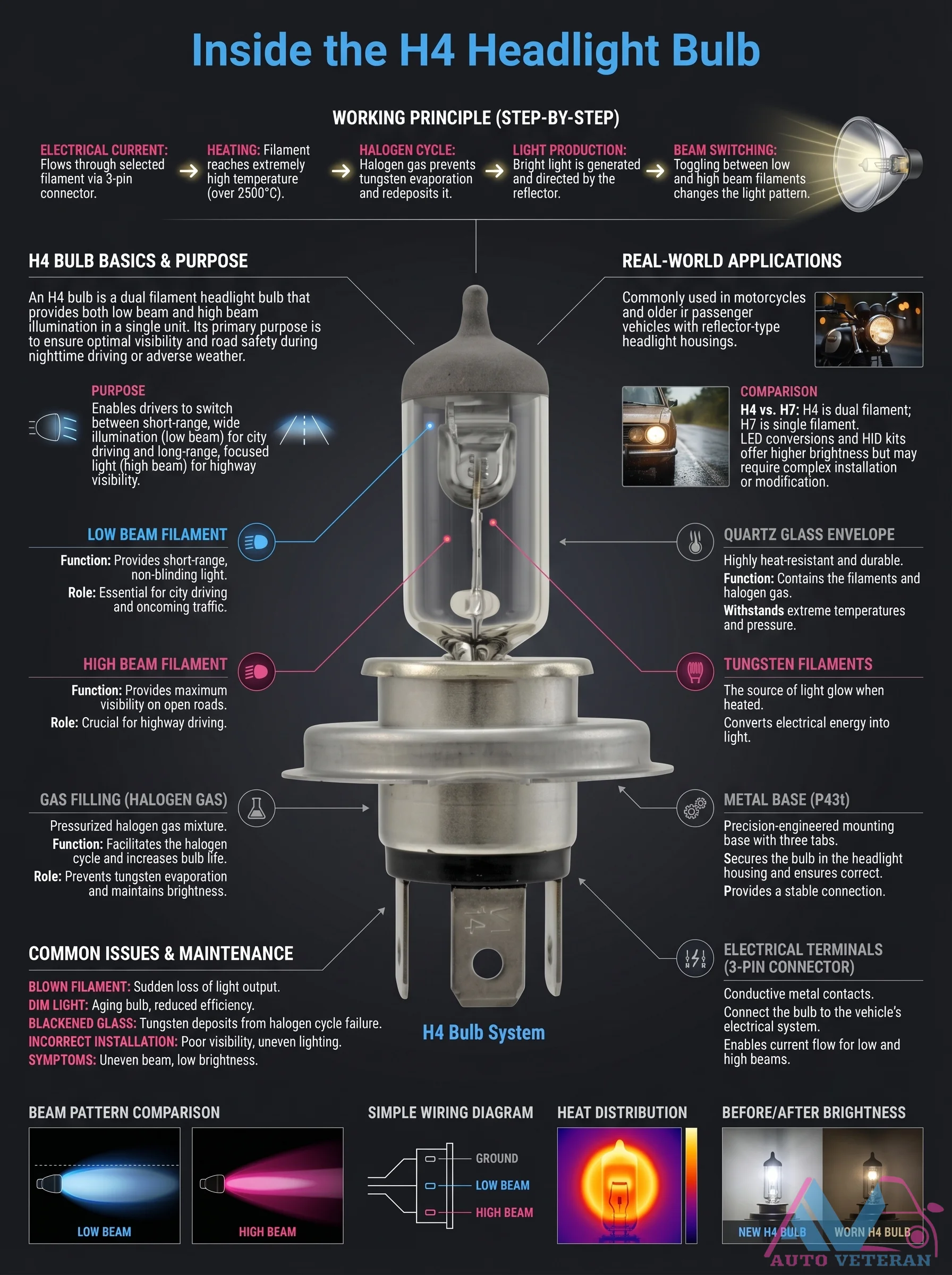
The H4 dual filament headlight bulb operates through a precise electrical and thermal process; electrical current flows through the selected filament via a 3 pin connector, heating the tungsten filament to about 2500°C. This triggers the halogen cycle, where halogen gas prevents tungsten evaporation and redeposits it, maintaining brightness and bulb life. The quartz glass envelope withstands extreme heat and pressure, while beam switching toggles between low and high beam filaments to change the light pattern for optimal visibility in various driving conditions.
Hall-Effect VSS P0500 Failure Symptoms
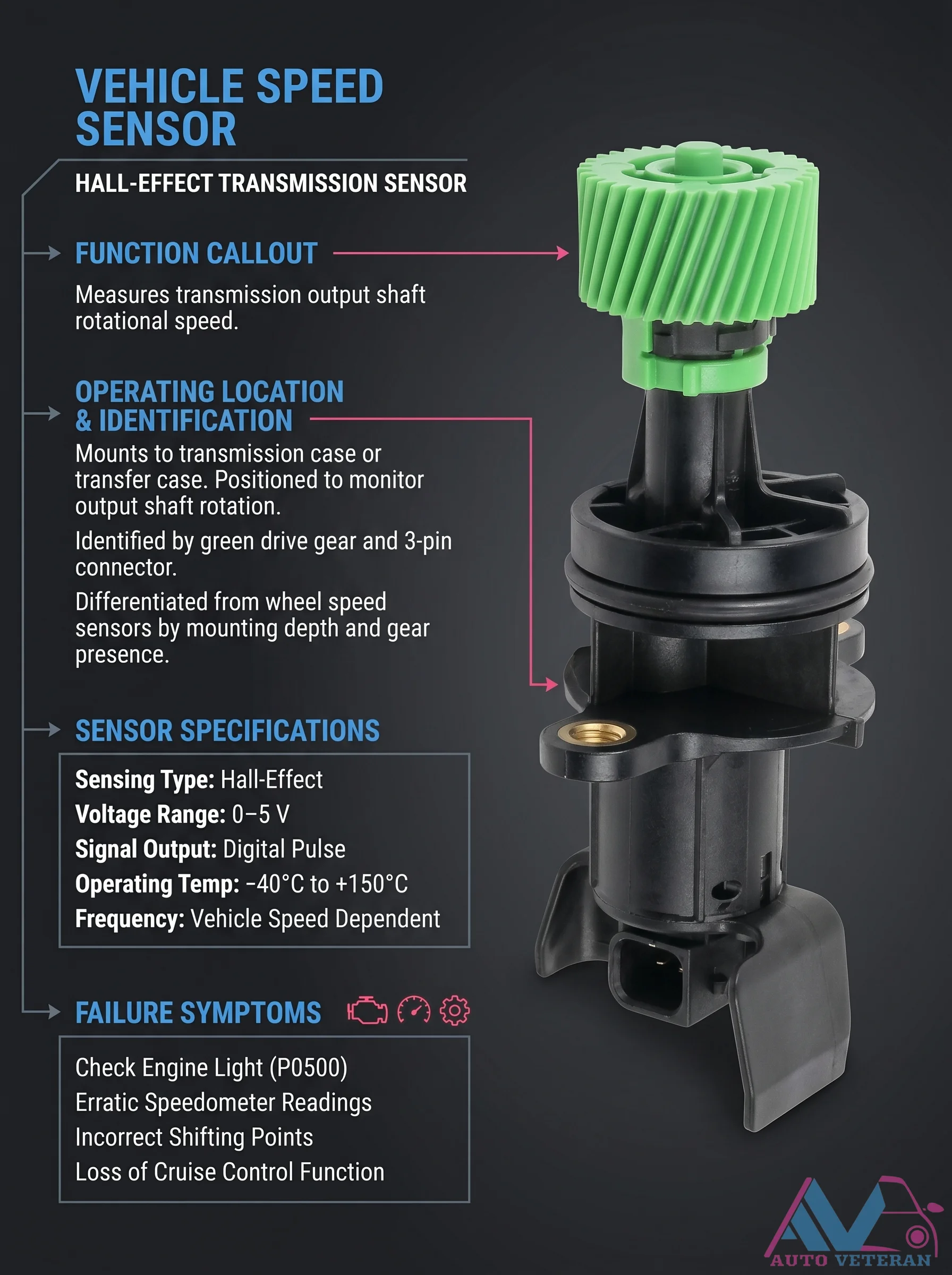
This Hall-Effect Vehicle Speed Sensor monitors transmission output shaft rotational speed via a digital pulse signal. Mounted to the transmission case with a green drive gear and 3-pin connector, it operates on a 0-5V range. When failing, it triggers a P0500 code, erratic speedometer, incorrect shifting, and cruise control loss.
Helicopter Aerodynamics and Flight Control Systems
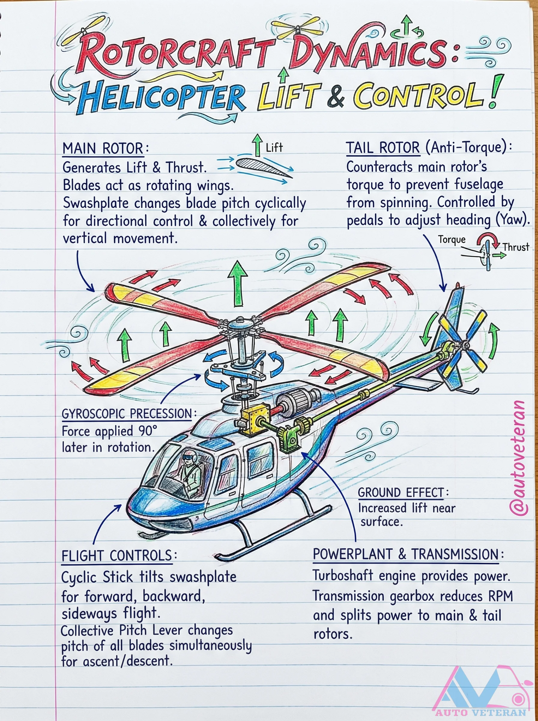
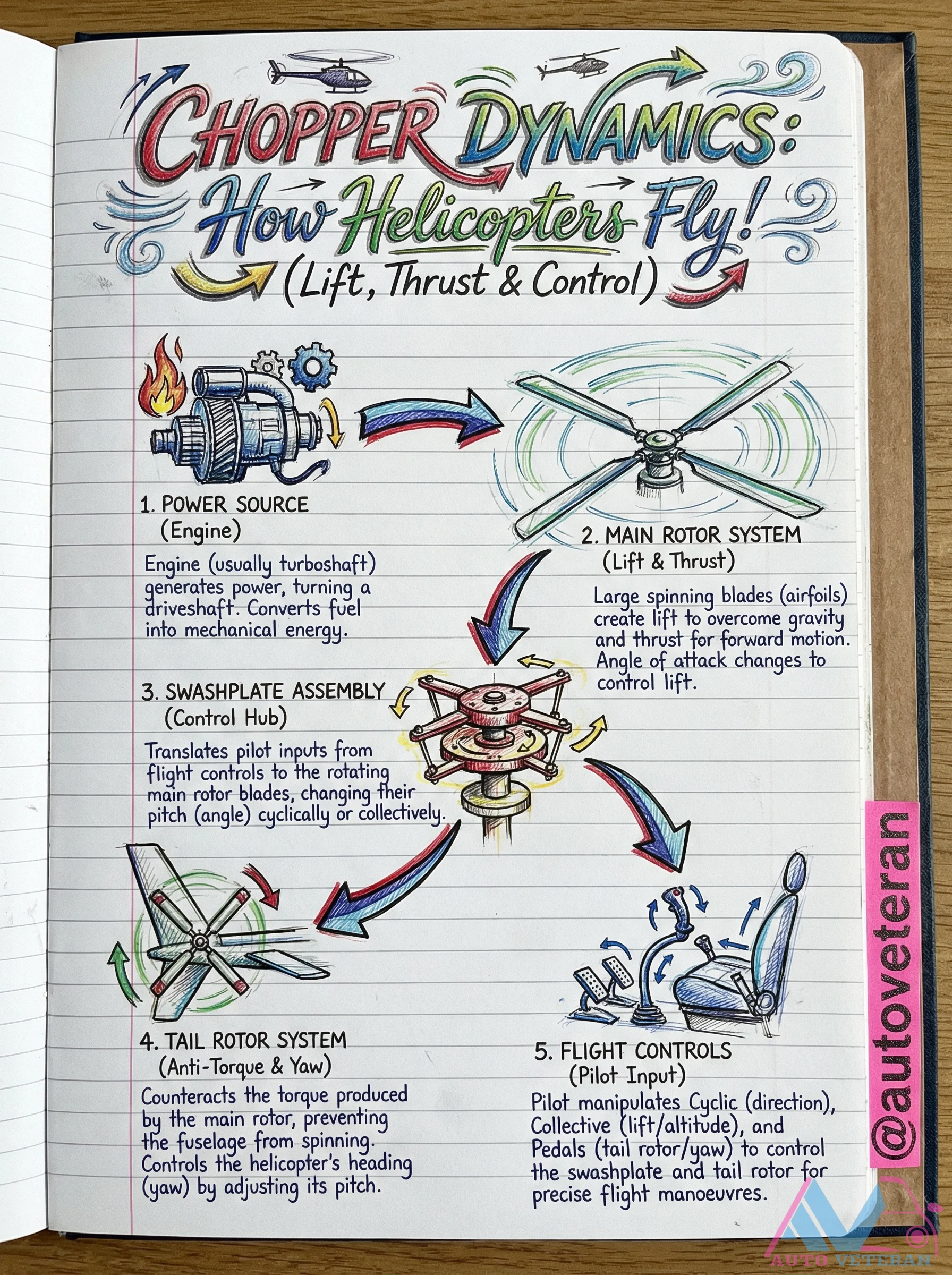
Helicopter flight dynamics involve complex interactions between lift generation, torque management, and precise control systems. The main rotor creates lift and thrust through blades that function as rotating wings, while the tail rotor counteracts the main rotor's torque to prevent fuselage spinning, controlled via pedals for yaw adjustments. Gyroscopic precession causes control inputs to manifest 90 degrees later in rotation, and ground effect provides increased lift near surfaces. Flight controls include the cyclic stick that tilts the swashplate for directional movement, and the collective pitch lever that simultaneously adjusts all blade angles for vertical ascent or descent. Power comes from turboshaft engines through transmission systems that reduce RPM and distribute power to both main and tail rotors.
Helicopter Aerodynamics, Components, and Flight Controls
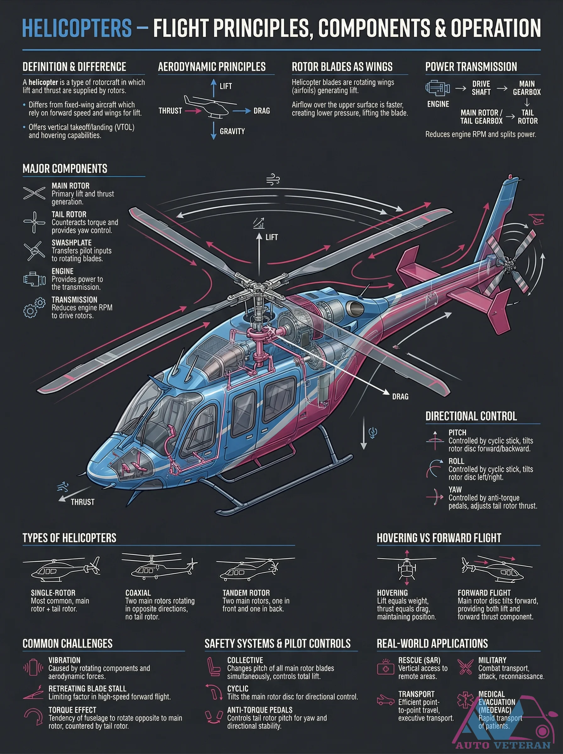
Helicopters operate on aerodynamic principles where rotating rotor blades function as wings, generating lift through airflow differences. Key components include the main rotor for lift and thrust, tail rotor for yaw control and countering torque, transmission systems that reduce engine RPM, and the swashplate that translates pilot inputs. Flight controls involve the cyclic stick for pitch and roll by tilting the rotor disc, collective stick for adjusting total lift via blade pitch, and anti-torque pedals for yaw control. Helicopters support vertical takeoff and landing, hovering, and forward flight, with applications in rescue, military, and transport operations.
Helicopter Aerodynamics, Components, and Flight Principles
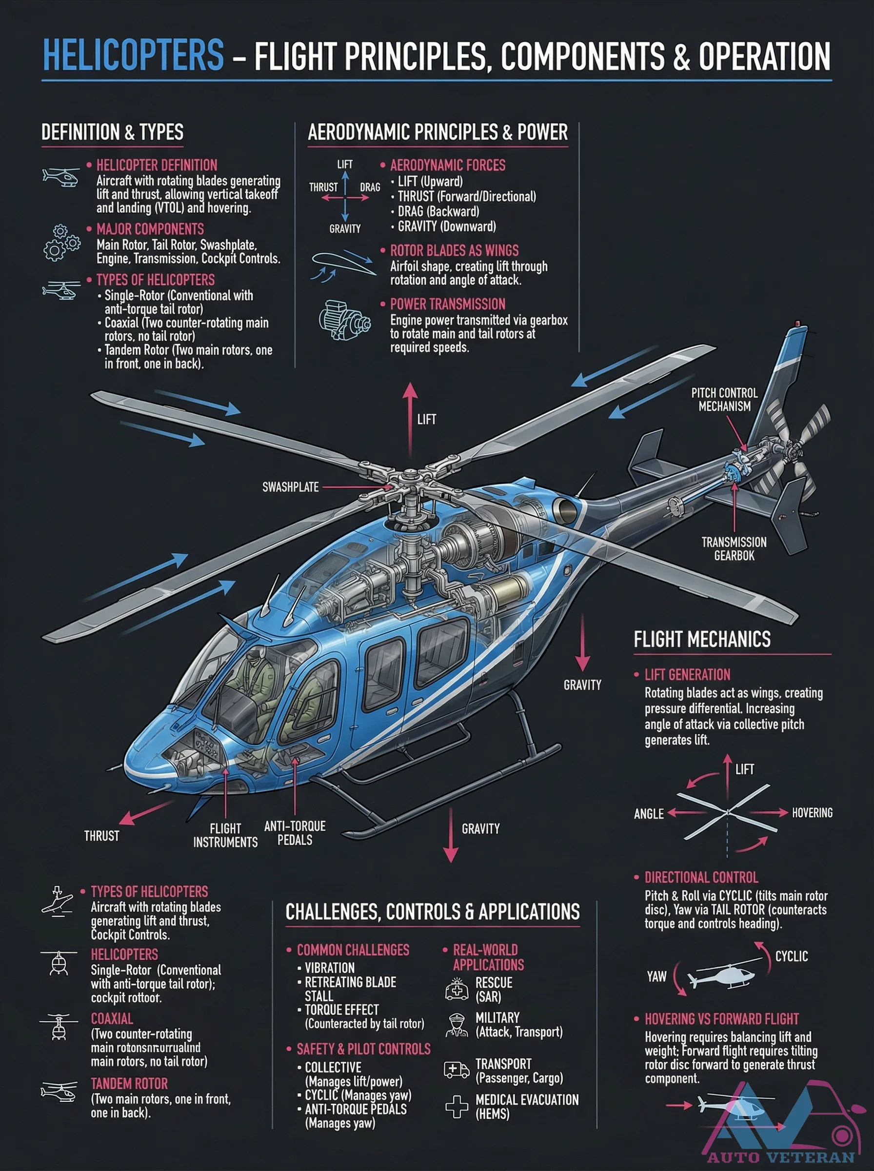
Helicopters operate through complex aerodynamic principles where rotating blades act as wings, generating lift via pressure differentials and angle of attack adjustments. Key components include the main rotor, tail rotor, swashplate, and transmission system, which work together to manage thrust, drag, lift, and gravity for vertical takeoff and hovering. The image details various helicopter types such as single-rotor, coaxial, and tandem rotor configurations, along with flight mechanics like pitch control, anti-torque mechanisms, and the challenges of vibration and retreating blade stall. Real world applications span rescue operations, military missions, and medical evacuations, highlighting the versatility of these aircraft.
Helicopter Dynamics Power Source and Main Rotor System
The helicopter's power source, typically a turboshaft engine, converts fuel energy into mechanical power that drives the main rotor system. This system features large spinning blades with airfoil shapes that generate lift to overcome gravity and thrust for forward motion. By adjusting the angle of attack on these blades, pilots can precisely control lift and thrust, enabling the complex flight dynamics unique to rotary wing aircraft.
Helicopter Flight Controls and Lift Mechanics
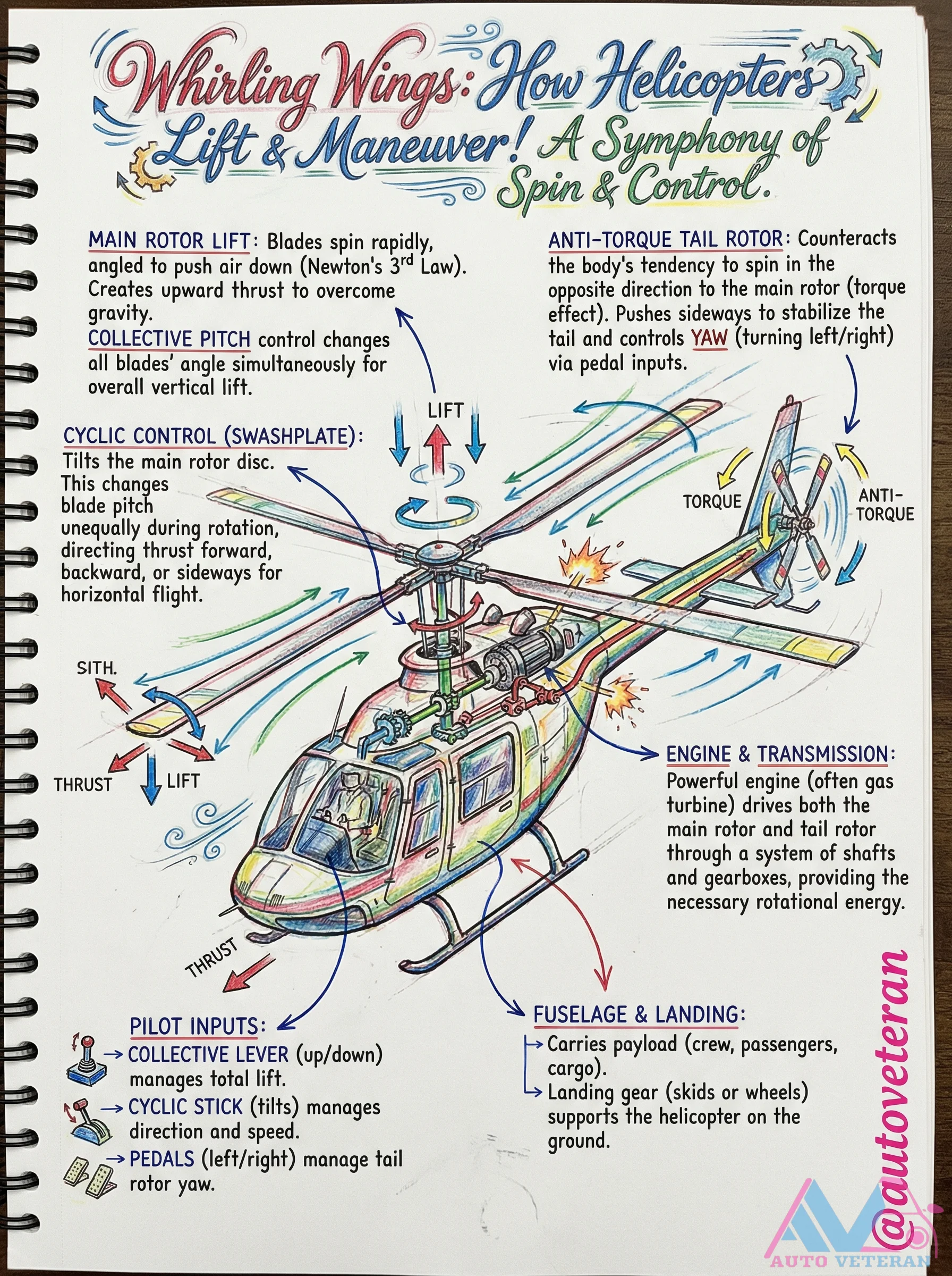
Helicopters achieve flight through the coordinated operation of main and tail rotors, with the main rotor generating lift by spinning blades angled to push air downward according to Newton's third law, while the tail rotor counteracts torque to prevent spinning. The collective pitch control adjusts all blade angles simultaneously for vertical lift, the cyclic control tilts the rotor disc via a swashplate for directional movement, and pedals manage yaw through tail rotor adjustments. A powerful engine, often a gas turbine, drives both rotors through a transmission system, enabling precise pilot inputs for hovering, forward flight, and stabilization.
Helicopter Flight Power Source Transmission and Drive
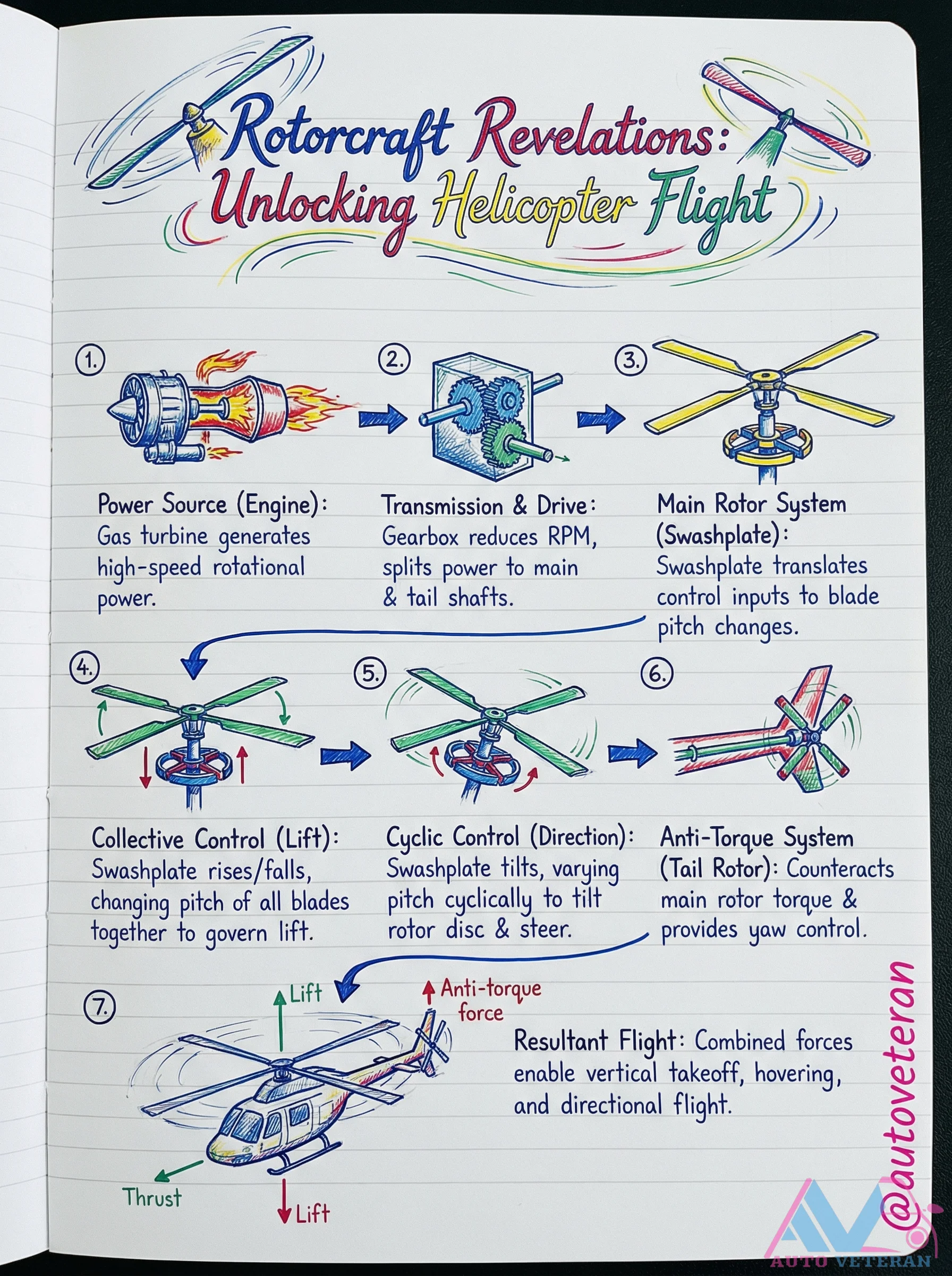
In rotorcraft operations, the gas turbine engine generates high-speed rotational power that is transmitted through a gearbox to reduce RPM for the main rotor system; the swashplate splits this power to both main and tail shafts while translating control inputs into blade pitch changes for collective lift, cyclic direction, and anti-torque yaw control, enabling vertical takeoff, hovering, and directional flight.
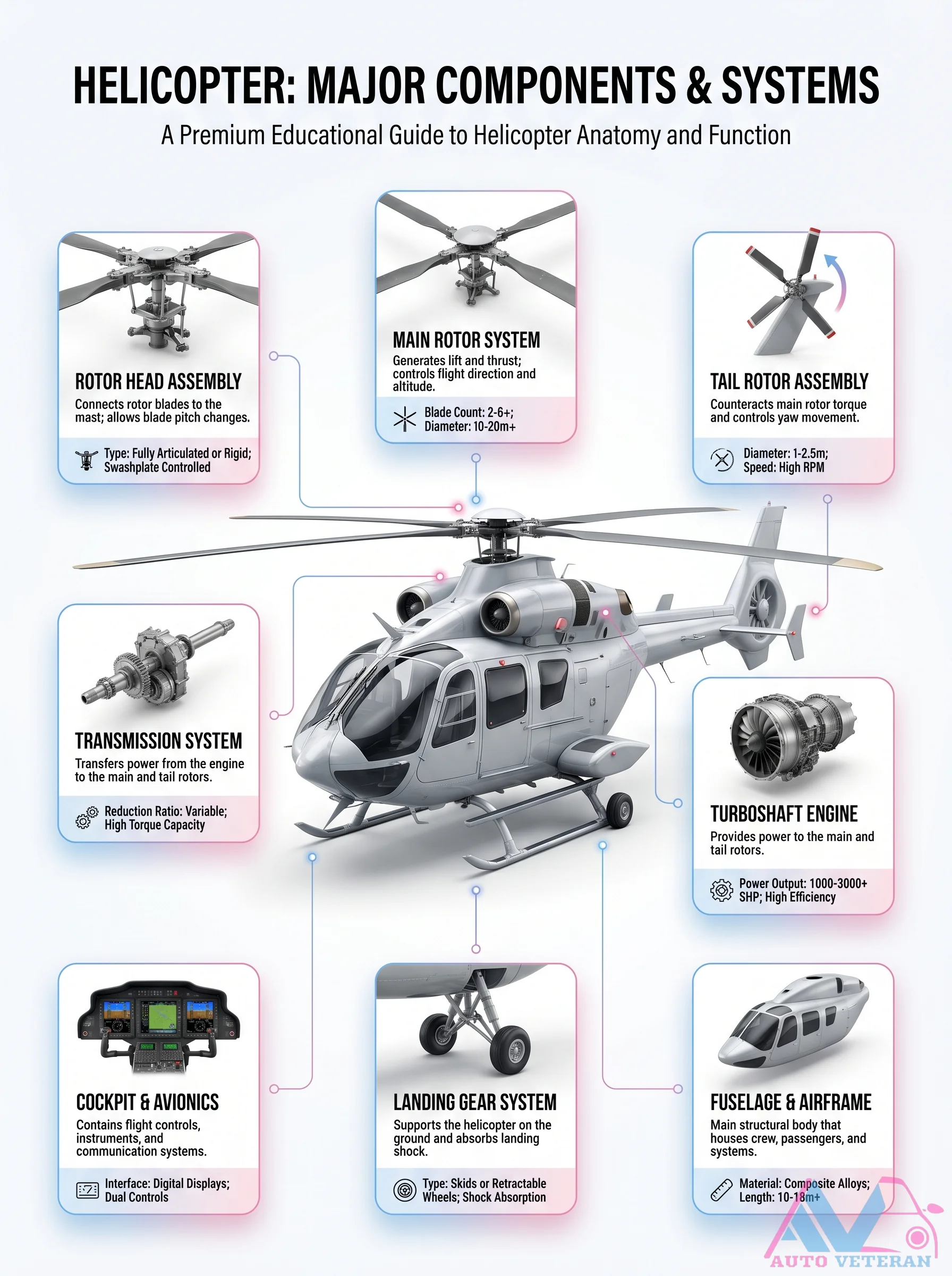
Helicopter Major Components & Systems
This comprehensive guide details the anatomy and function of a helicopter: the main rotor system with its rotor head assembly and blade pitch changes; the tail rotor assembly counteracting torque; the transmission system transferring power at variable reduction ratios; the turboshaft engine providing 1000-3000+ SHP; the cockpit with digital displays and dual controls; the landing gear with skids or retractable wheels; and the fuselage constructed from composite alloys. Each system works together to achieve lift, thrust, and directional control.
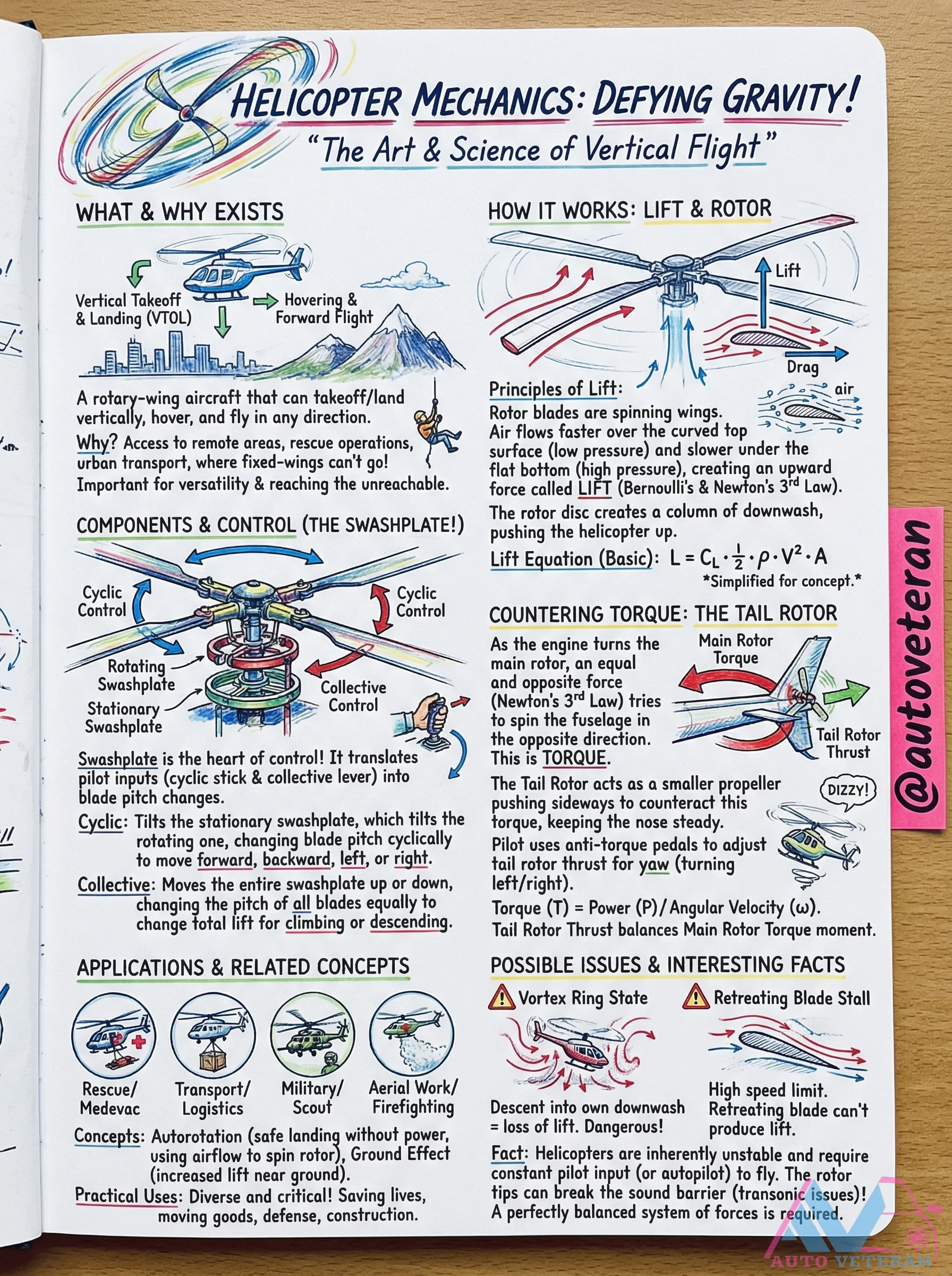
Helicopter Mechanics and VTOL Principles
Helicopter mechanics involve the art and science of vertical flight, focusing on Vertical Takeoff and Landing (VTOL) capabilities that enable access to remote areas and rescue operations. Key principles include lift generated by rotor blades acting as spinning wings, where air flows faster over curved surfaces to create upward force. The swashplate serves as the heart of control, translating pilot inputs into blade pitch changes for cyclic and collective movements. To counter torque from the main rotor, a tail rotor provides sideways thrust to maintain stability and control yaw. Applications span rescue, transport, military, and aerial work, while challenges like vortex ring state and retreating blade stall highlight the complexity of maintaining a perfectly balanced system of forces for safe hover and flight.
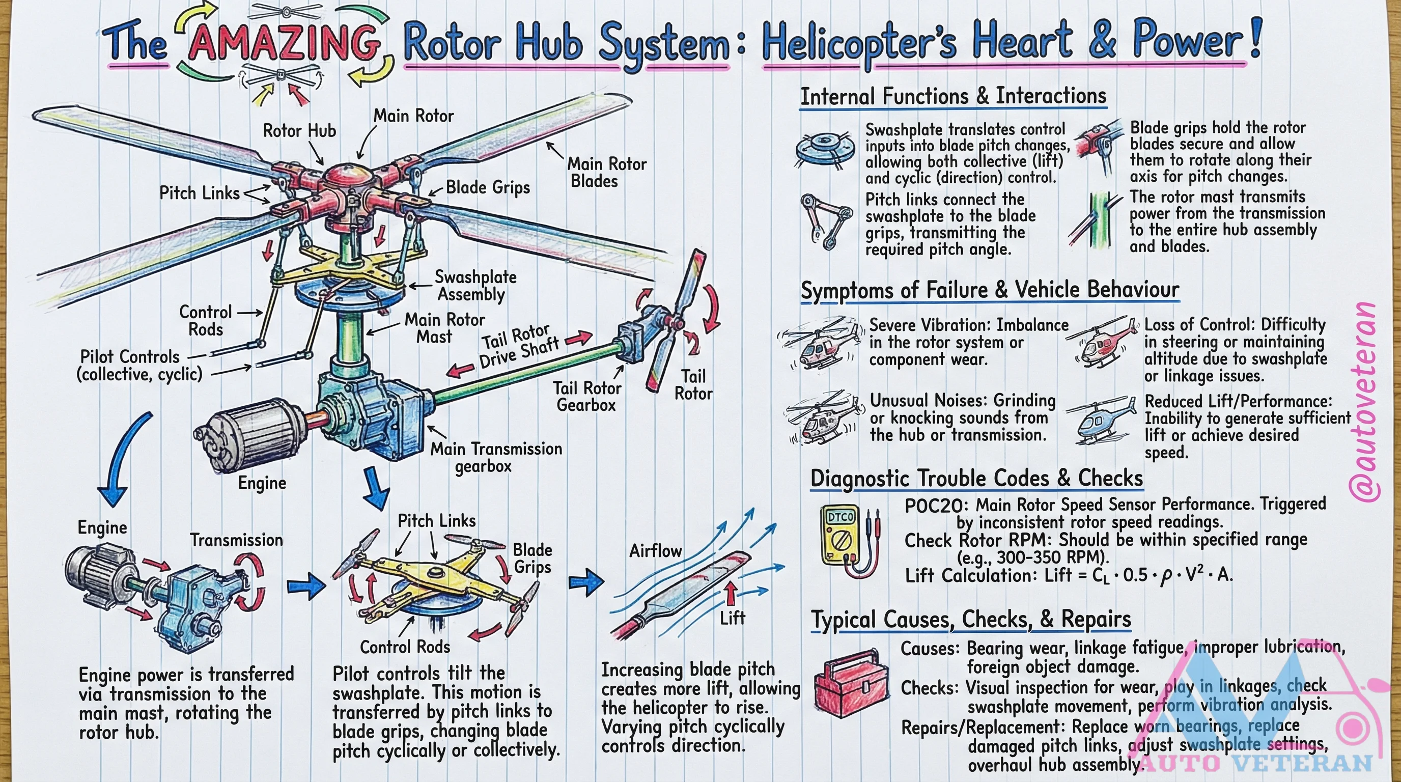
Helicopter Rotor Hub Failure Symptoms and Diagnosis
The rotor hub system, often called the helicopter's heart, is critical for flight control and power transmission. When components like bearings, pitch links, or blade grips fail, symptoms include severe vibration, loss of control, unusual grinding noises, and reduced lift performance. Diagnostic checks involve visual inspections for wear, vibration analysis, and verifying rotor speed sensor readings, such as ensuring RPM stays within the 300 to 500 range. Common causes are bearing wear, improper lubrication, or foreign object damage, with repairs typically requiring bearing replacement, pitch link adjustments, or a full hub assembly overhaul.
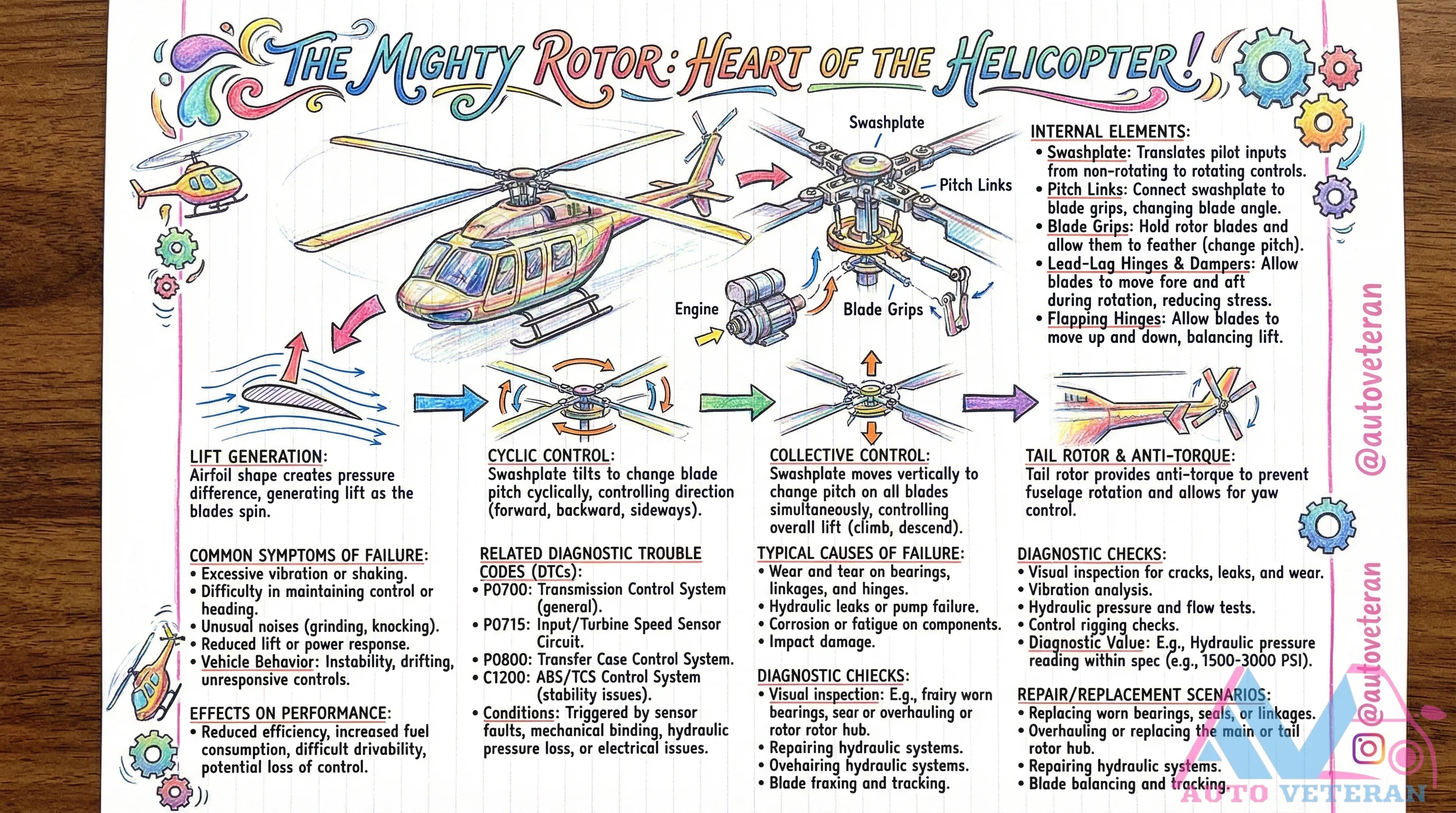
Helicopter Swashplate Failure Symptoms and Diagnosis
The swashplate serves as the critical heart of helicopter flight control, translating pilot inputs into precise rotor blade movements. When this complex assembly fails, pilots experience excessive vibration and shaking, difficulty maintaining heading control, unusual grinding or knocking noises, and reduced lift power. Diagnostic trouble codes like P0700, P0715, and P0800 often accompany these symptoms, indicating transmission control system issues, input speed sensor problems, or transfer case malfunctions. Common causes include wear and tear on bearings and linkages, hydraulic leaks or pump failures, corrosion fatigue, impact damage, and mechanical binding. Technicians perform visual inspections for cracks and leaks, vibration analysis, hydraulic pressure and flow tests, and control rigging checks to pinpoint issues. Repair scenarios involve replacing worn bearings and seals, overhauling or replacing the rotor hub, repairing hydraulic systems, and performing blade tracking and balancing. These failures lead to reduced efficiency, increased fuel consumption, difficult drivability, and potential control instability, making timely diagnosis essential for safe flight operations.
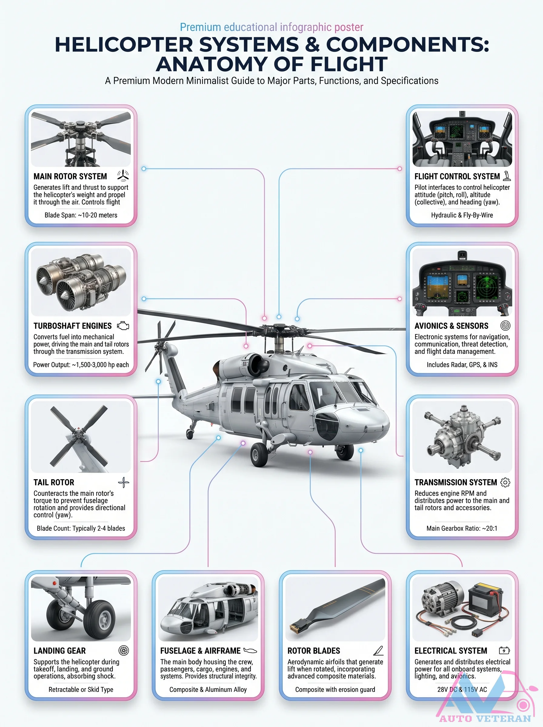
Helicopter Systems and Components Poster
This premium educational infographic breaks down the anatomy of flight across every major helicopter subsystem, from the main rotor generating 10 to 20 meters of lift and the turboshaft engines delivering 500 to 3,000 horsepower each, to the fly by wire flight controls, avionics sensors including radar GPS and INS, and the transmission system with a main gearbox ratio of approximately 20 to 1; it also covers the tail rotor counter torque, landing gear types such as retractable or skid, and the composite rotor blades and electrical system.
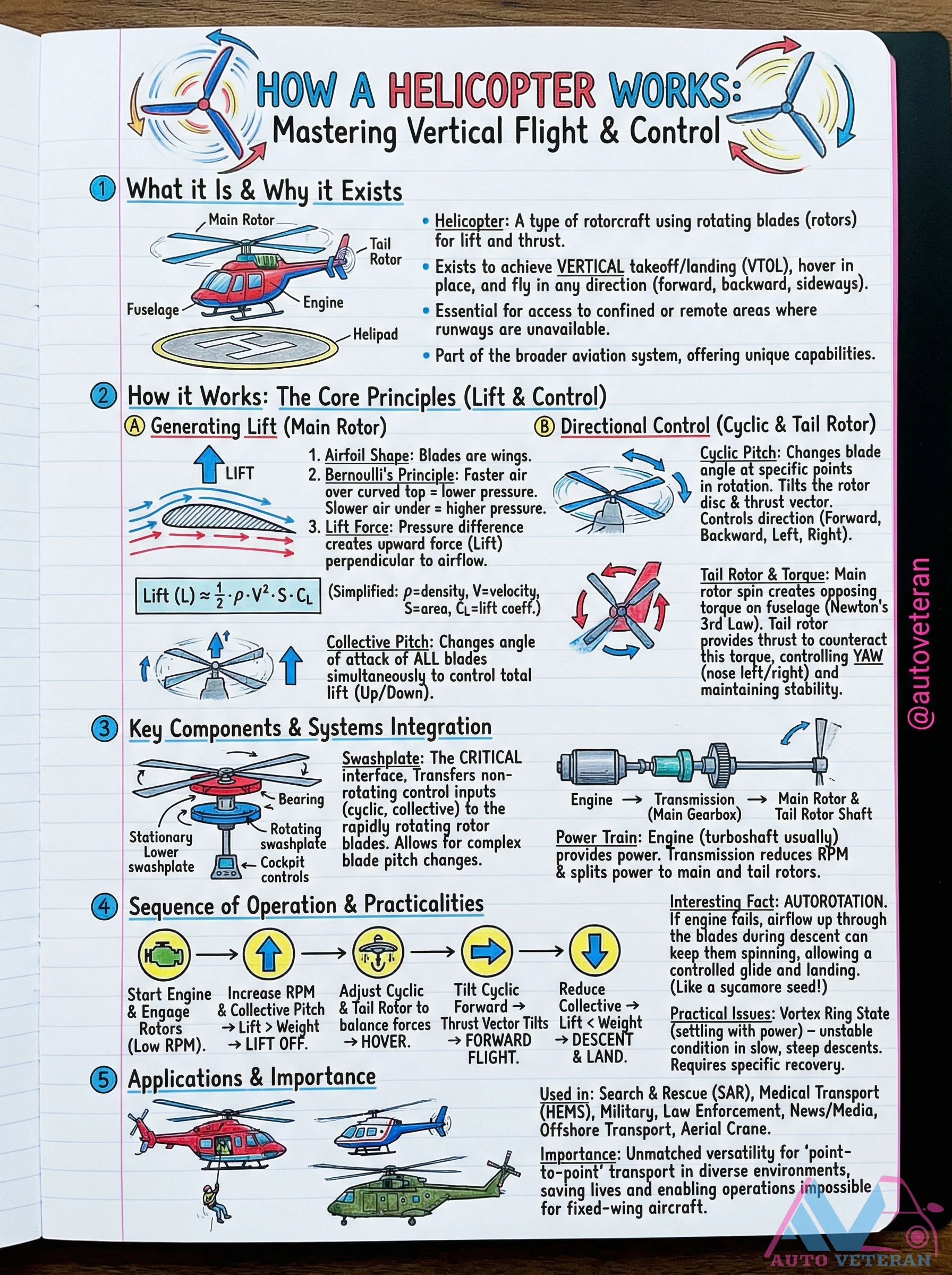
Helicopter Vertical Flight and Control Principles
Helicopters achieve vertical takeoff and landing through main rotor lift generation using airfoil blades and Bernoulli's principle. The cyclic and collective pitch controls allow directional movement while the tail rotor counters torque from the main rotor. Key systems like the swashplate transfer control inputs to rotating blades, enabling complex maneuvers including autorotation during engine failure. This unique VTOL capability provides access to confined areas where traditional runways are unavailable.
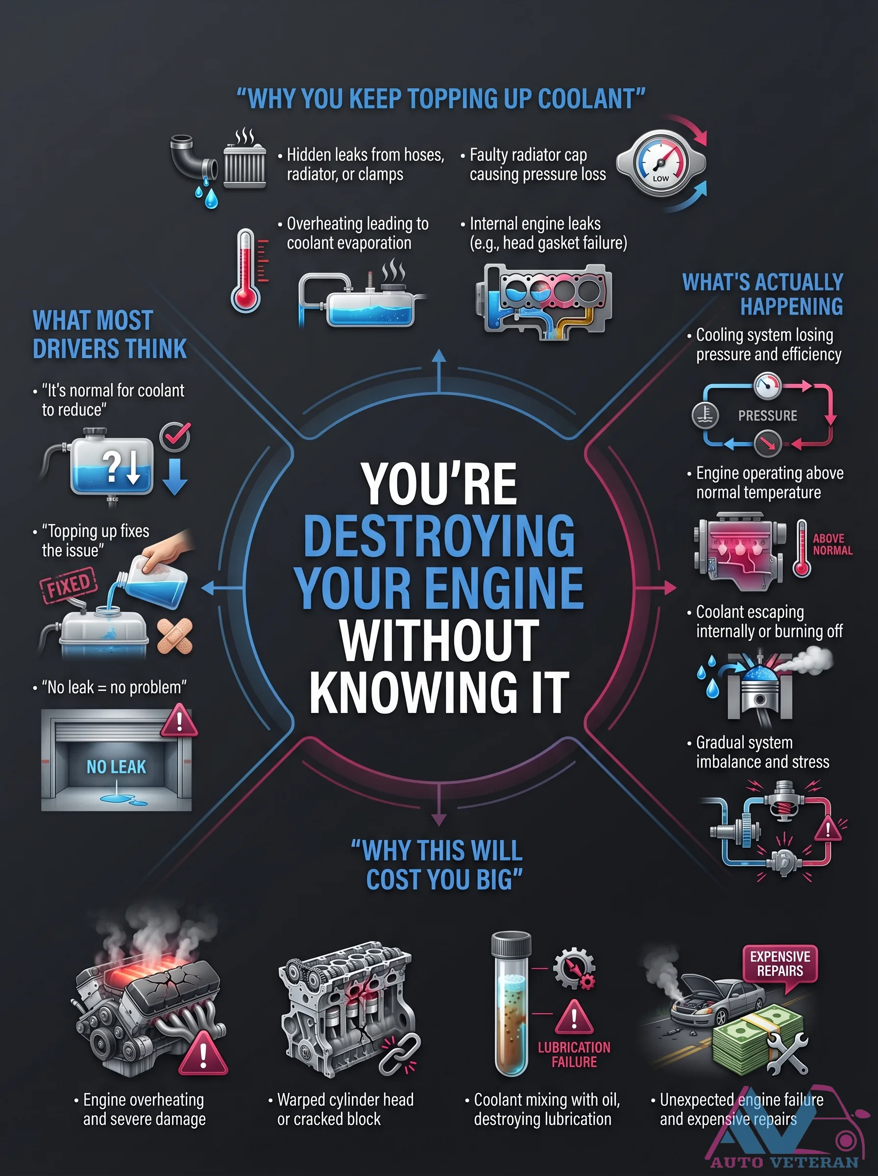
Hidden Coolant Leaks Causing Overheating and Engine Damage
Persistent coolant loss often stems from hidden leaks in hoses, clamps, or a faulty radiator cap, leading to pressure loss and system inefficiency. This causes the engine to operate above normal temperature, accelerating coolant evaporation and potentially resulting in internal leaks like head gasket failure. Ignoring these issues by repeatedly topping up coolant can lead to severe consequences, including lubrication failure from coolant mixing with oil, warped cylinder heads, cracked engine blocks, and ultimately catastrophic engine failure requiring expensive repairs.
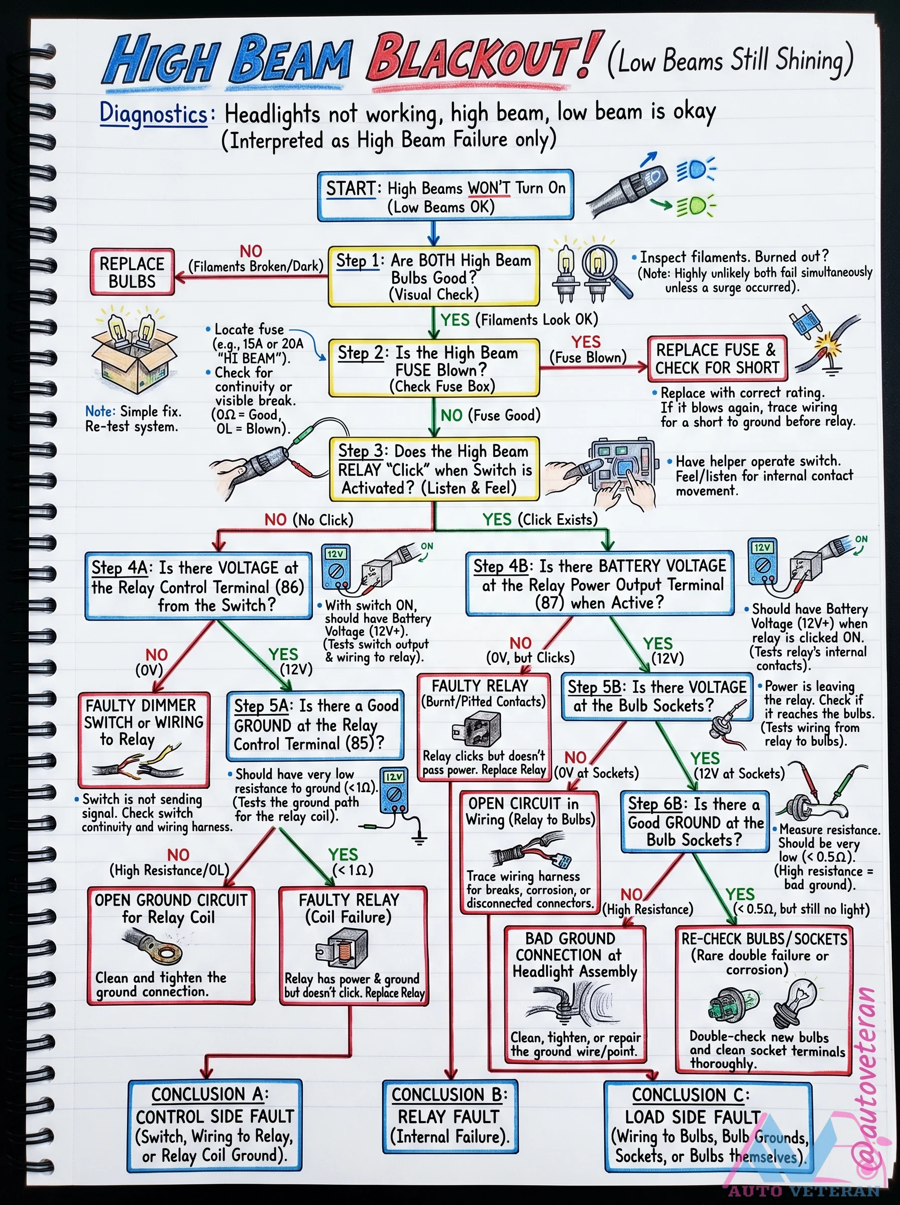
High Beam Blackout Diagnostic Flowchart
When your low beams work but the high beams refuse to illuminate, follow this systematic diagnostic flowchart. It walks you through testing filaments, the 20A fuse, the relay clicks, control and power terminals, ground paths, and voltage at bulb sockets. The chart concludes with three possible fault categories: control side (switch, dimmer), relay failure, or load side (wiring, grounds, sockets).
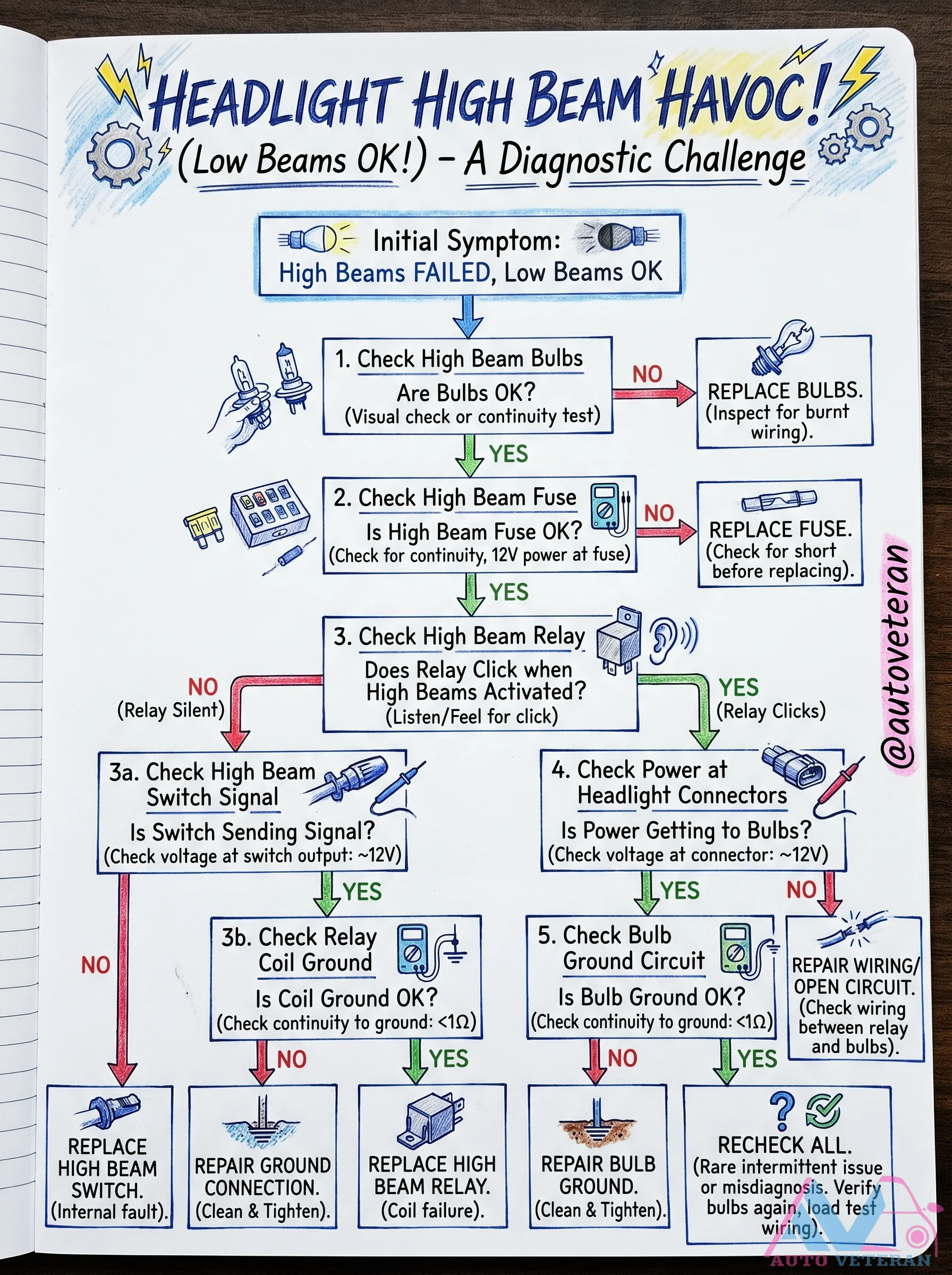
High Beam Diagnostic Flowchart
A systematic diagnostic chart for troubleshooting High Beam failure when Low Beams work: Start by checking bulbs visually or with a continuity test, then test the fuse for continuity and 12V power, listen for the relay clicking to verify activation, measure voltage at the switch output and headlight connector, check ground circuits for low resistance, and finally inspect wiring between relay and bulbs for shorts or opens. Each step branches to REPLACE or REPAIR actions for bulbs, fuses, relays, switches, grounds, and wiring.
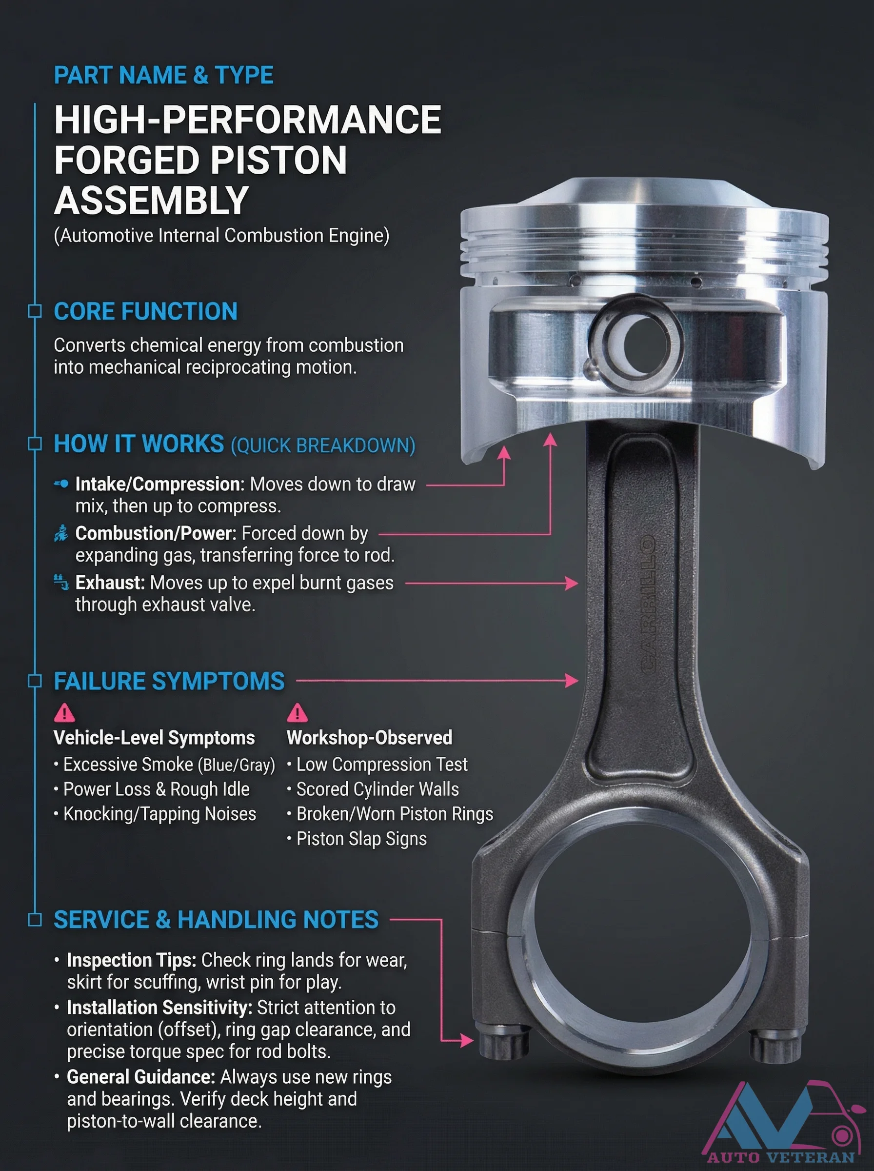
High-Performance Forged Piston Failure Symptoms and Inspection
When a high-performance forged piston assembly begins to fail, multiple symptoms manifest at both vehicle and workshop levels. Drivers experience power loss, rough idle, and knocking or tapping noises from the engine bay. During compression testing, technicians observe low readings and excessive blue smoke from the exhaust. Physical inspection reveals scored cylinder walls, broken or worn piston rings, piston slap signs, and worn wrist pins with excessive play. Proper installation requires strict attention to piston orientation with offset, precise ring gap clearance, and exact torque specifications for connecting rod bolts. Always use new rings and bearings during assembly, and verify critical measurements including deck height and piston-to-wall clearance to ensure optimal performance and longevity.
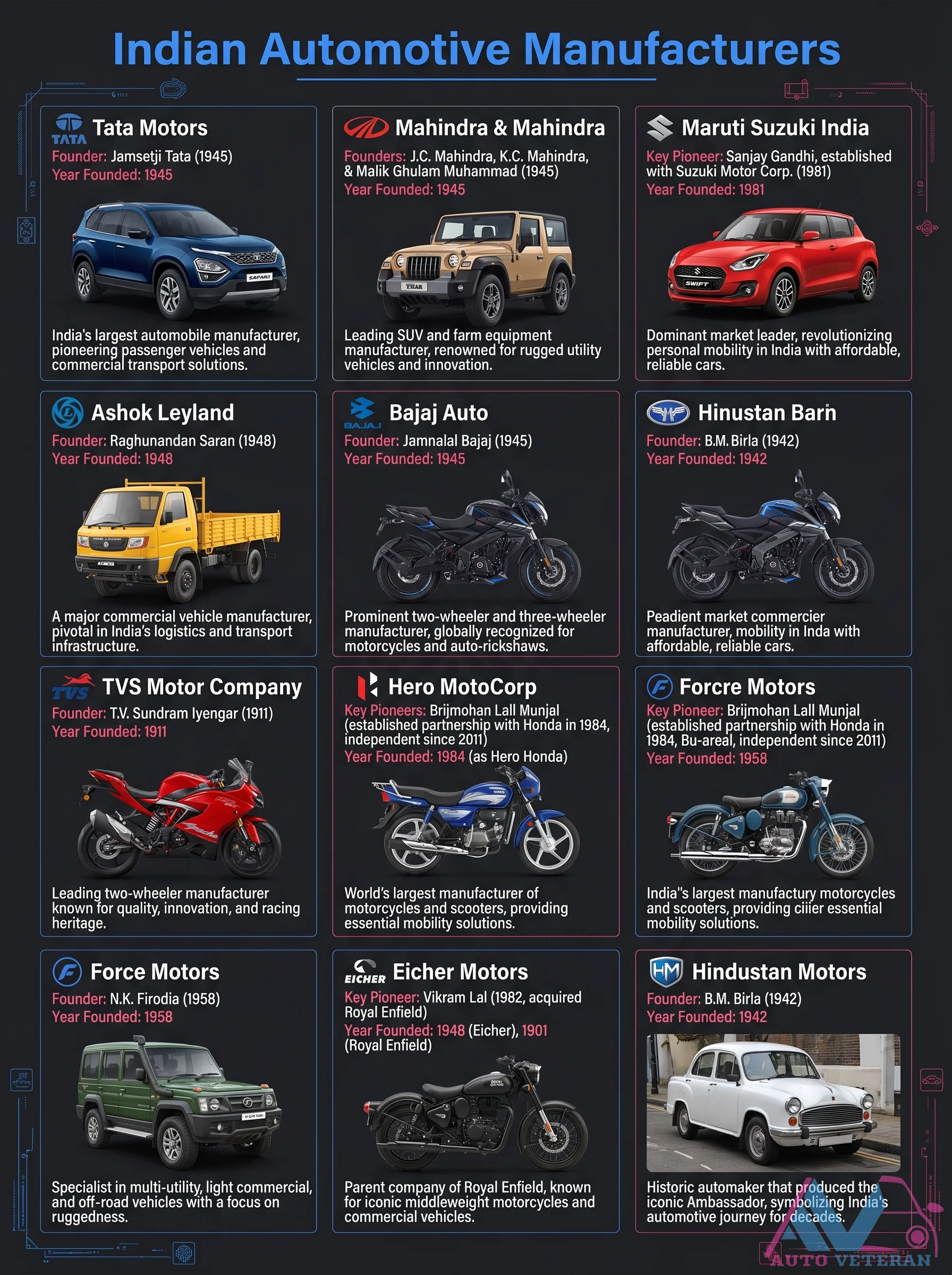
History of Indian Automotive Manufacturers
This educational overview showcases the founding years and key figures behind India's major automotive manufacturers including Tata Motors, Mahindra & Mahindra, and Maruti Suzuki India. Tata Motors was founded in 1945 by Jamsetji Tata. Mahindra & Mahindra was founded in 1945 by J.C. Mahindra and K.C. Mahindra, with Malik Ghulam Muhammad. Maruti Suzuki was established in 1981 with a key role by Sanjay Gandhi and Suzuki Motor. Other notable companies featured are Ashok Leyland (1948), Bajaj Auto (1945), Hindustan Motors (1942), TVS Motor (1911), Hero MotoCorp (1984), Force Motors (1958), Eicher Motors (1948), and Royal Enfield (1901).
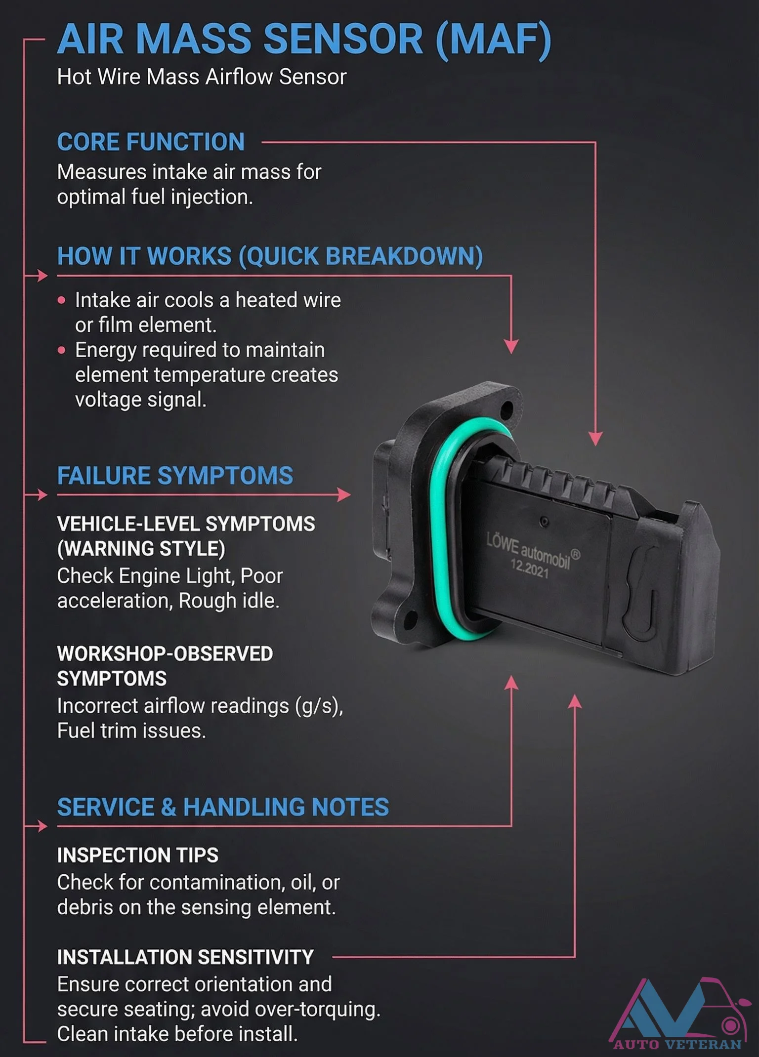
Hot-Wire MAF Sensor Failure Symptoms and Inspection
When a hot-wire mass airflow sensor fails, it triggers vehicle-level symptoms like check engine lights, poor acceleration, and rough idle, while workshop diagnostics reveal incorrect airflow readings in grams per second and fuel trim issues. Proper inspection involves checking for contamination such as oil or debris on the sensing element, and installation requires correct orientation, secure seating without over-torquing, and a clean intake system to ensure accurate function.