Interactive Explorer
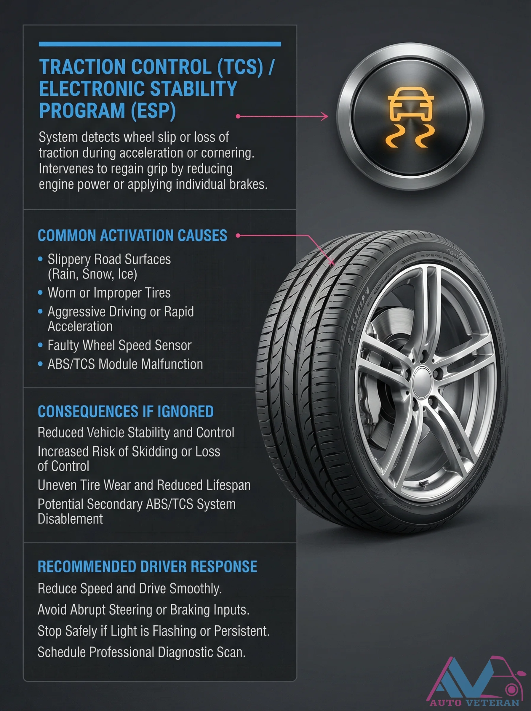
Traction Control ESP Warning Light Causes and Response
When your vehicle's Traction Control System or Electronic Stability Program detects wheel slip during acceleration or cornering, it intervenes to regain grip by reducing engine power or applying individual brakes. Common activation causes include slippery road surfaces like rain, snow, or ice; worn or improper tires; aggressive driving; faulty wheel speed sensors; or ABS/TCS module malfunctions. Ignoring this warning can lead to reduced vehicle stability, increased risk of skidding, uneven tire wear, and potential system disablement. The recommended driver response is to reduce speed, drive smoothly, avoid abrupt steering or braking, stop safely if the light flashes persistently, and schedule a professional diagnostic scan.
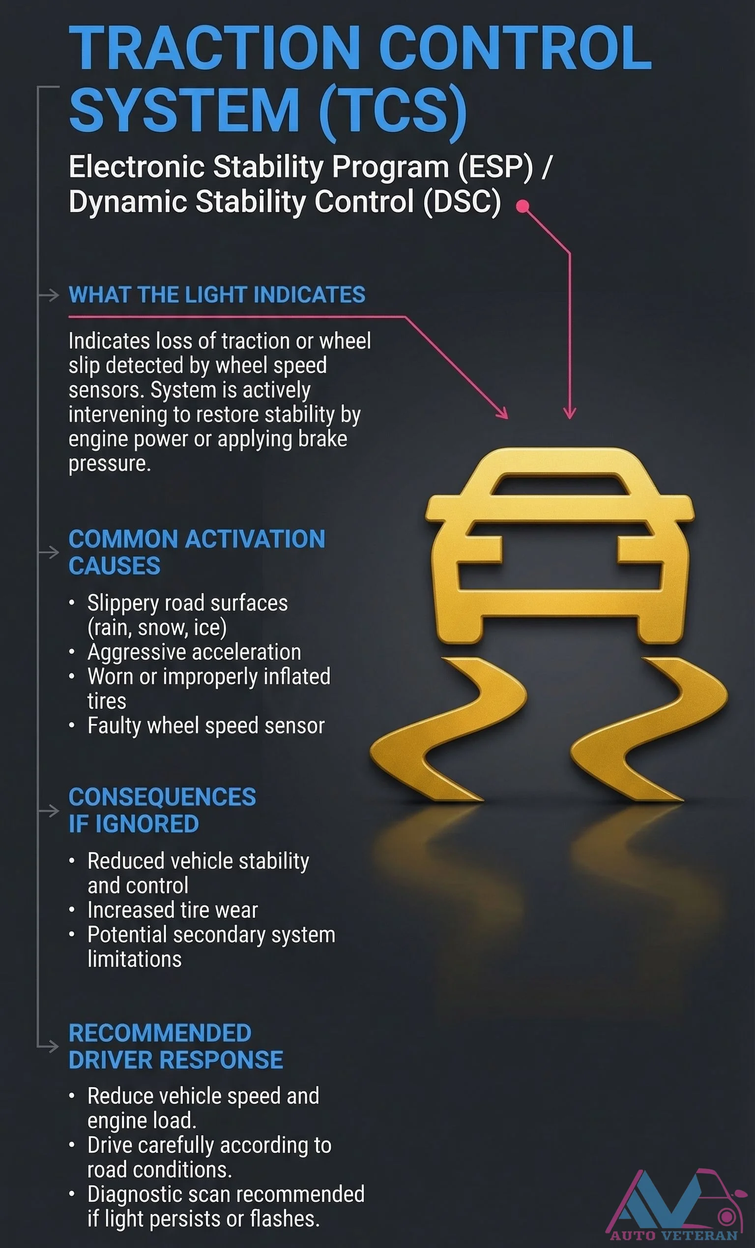
Traction Control Light Indications and Activation Causes
The traction control system light illuminates when wheel speed sensors detect loss of traction or wheel slip, signaling the system is actively intervening through engine power reduction or brake pressure application to restore vehicle stability. Common activation triggers include slippery road surfaces, worn tires, or faulty wheel speed sensors. Ignoring this warning can lead to reduced vehicle control, increased tire wear, and potential limitations in secondary safety systems. Drivers should respond by reducing speed and engine load, adapting driving to road conditions, and seeking diagnostic scanning if the light persists or flashes.
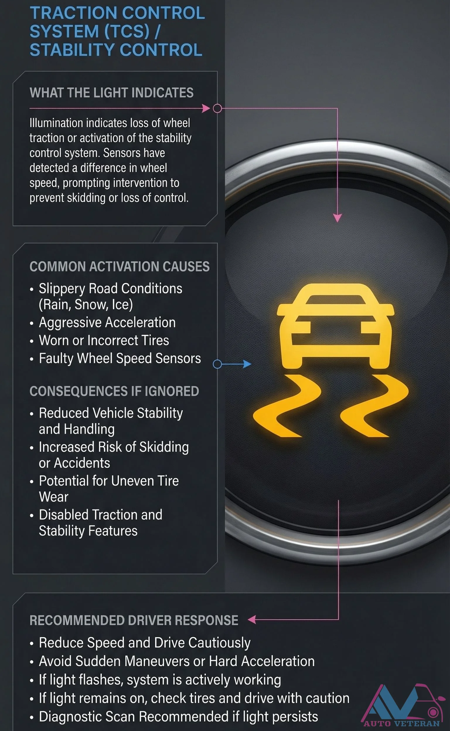
Traction Control Light Indications, Causes, and Driver Response
When your traction control system activates, the dashboard light illuminates to signal that wheel speed sensors have detected traction loss, prompting electronic intervention to prevent skidding. Common triggers include slippery road conditions like rain, snow, or ice, aggressive acceleration, worn tires, or faulty wheel speed sensors. Ignoring this warning reduces vehicle stability, increases accident risk, causes uneven tire wear, and may disable safety features. Recommended responses include reducing speed, avoiding sudden maneuvers, and checking tire condition, with a diagnostic scan if the light persists.
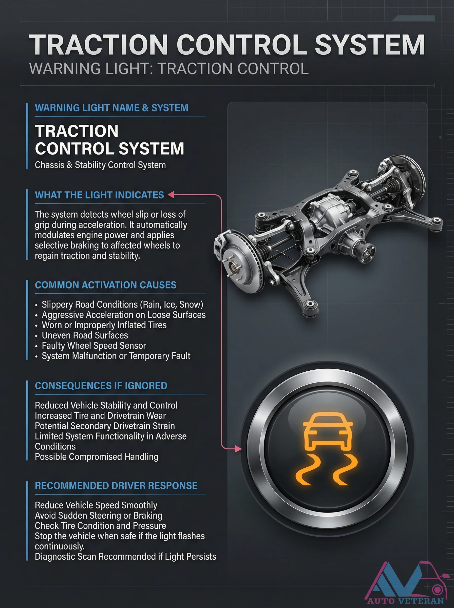
Traction Control Warning Light Causes and Driver Response
The traction control system warning light illuminates when the vehicle detects wheel slip or loss of grip during acceleration, indicating the system is actively modulating engine power and applying selective braking to maintain stability. Common activation causes include slippery road conditions like rain, ice, or snow, aggressive acceleration on loose surfaces, worn or improperly inflated tires, uneven road surfaces, faulty wheel speed sensors, or system malfunctions. Ignoring this warning can lead to reduced vehicle stability and control, increased tire and drivetrain wear, potential secondary drivetrain strain, limited system functionality in adverse conditions, and compromised handling. Recommended driver responses include reducing vehicle speed smoothly, avoiding sudden steering or braking maneuvers, checking tire condition and pressure, stopping the vehicle when safe if the light flashes continuously, and performing a diagnostic scan if the light persists.
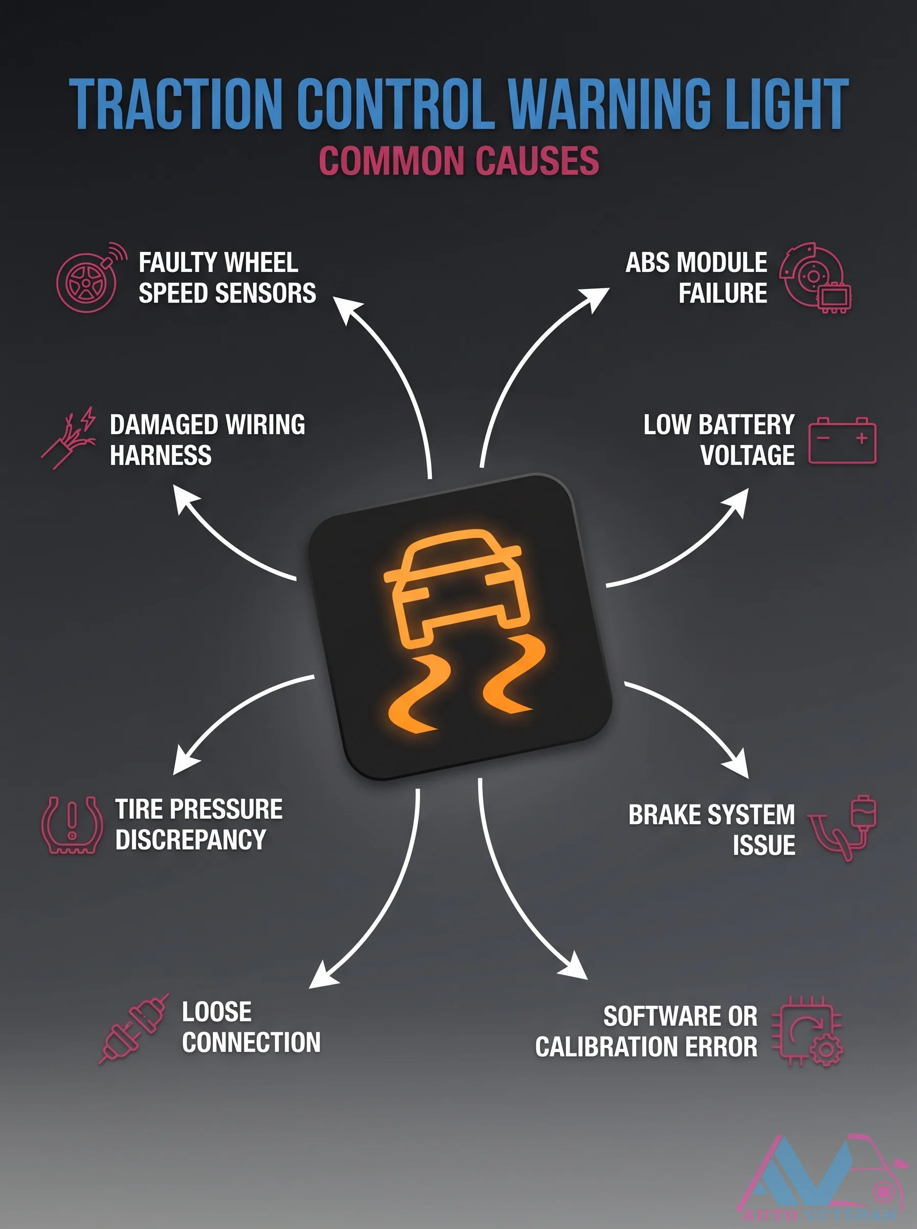
Traction Control Warning Light Common Causes
Your traction control warning light illuminates when your vehicle detects a fault in the stability system. Common triggers include a faulty wheel speed sensor, a failing ABS module, damaged wiring or harness connections, low battery voltage, tire pressure discrepancies, brake system issues, or software and calibration errors. Ignoring this warning can lead to reduced traction and stability in slippery conditions, so diagnosis should be prompt.

Tree Height Calculation Using Shadow Proportions
This practical geometry technique demonstrates how to determine a tree's height by measuring shadows and applying similar triangle principles. With a reference stick measuring 1.5 meters tall casting a 2-meter shadow, and the tree's shadow measuring 12 meters, the calculation reveals the tree stands 9 meters tall. The method relies on parallel sun rays creating proportional relationships between object heights and their corresponding shadows, providing a simple yet accurate field measurement solution without requiring direct access to the tree's crown.

Tree Height Calculation Using Similar Triangles
This practical demonstration shows how to calculate the height of a tree using the principle of similar triangles and shadow measurements. With a person's height of 1.6 meters, their shadow length of 2.4 meters, and the tree's shadow length of 18.0 meters, the calculation reveals the tree stands approximately 12 meters tall. The method relies on the constant ratio between height and shadow length when the sun's angle is identical for both objects, proving mathematical concepts work effectively in real world applications.
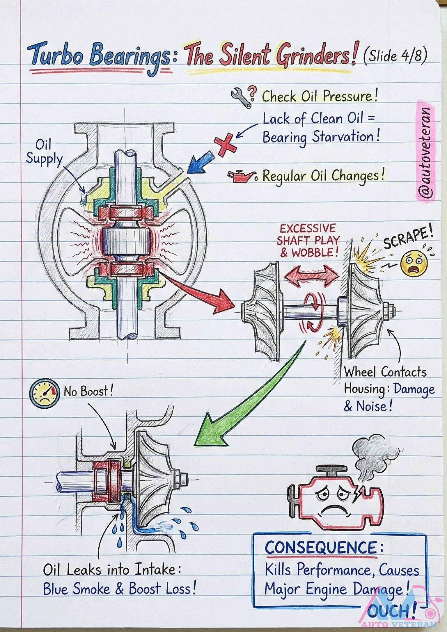
Turbo Bearing Failure Consequences from Oil Issues
When turbocharger bearings fail due to inadequate oil pressure or contamination, the consequences are severe and multifaceted. Excessive shaft play develops, causing the compressor wheel to contact the housing, which eliminates boost pressure and creates damaging noise. Oil leaks into the intake system kill engine performance while producing telltale blue smoke from burning oil. This cascade of failures ultimately leads to major engine damage if not addressed promptly through proper maintenance like regular oil changes and monitoring oil supply quality.
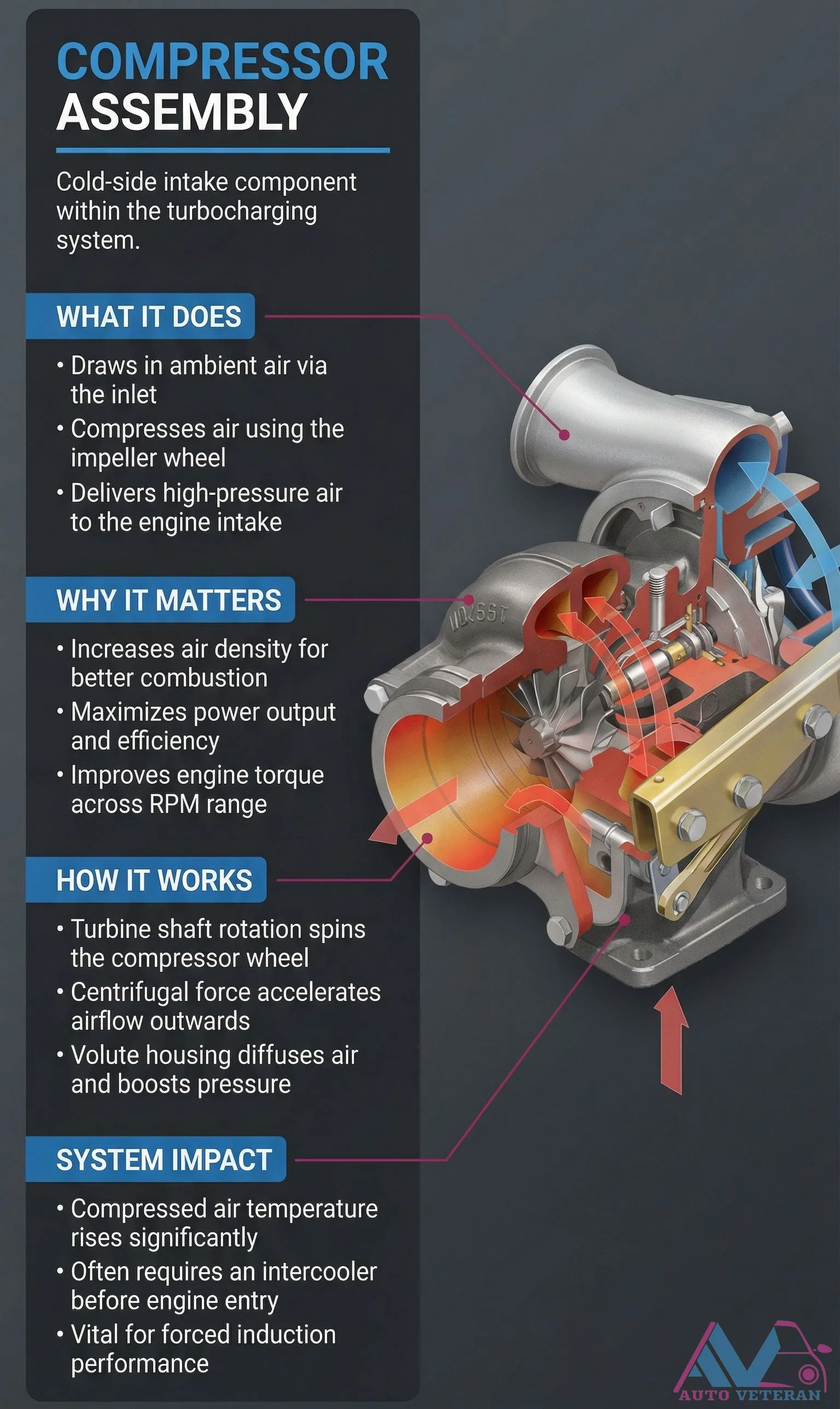
Turbo Compressor Assembly Function and System Impact
The cold-side compressor assembly is the critical intake component in turbocharging systems that draws ambient air through its inlet, compresses it via the impeller wheel, and delivers high-pressure air to the engine intake. This process increases air density for superior combustion, maximizes power output and efficiency, and improves engine torque across the entire RPM range. As the turbine shaft rotates, it spins the compressor wheel, using centrifugal force to accelerate airflow outward while the volute housing diffuses the air and boosts pressure. The system impact includes significant temperature rises in compressed air, often necessitating an intercooler before engine entry, making this assembly vital for forced induction performance.
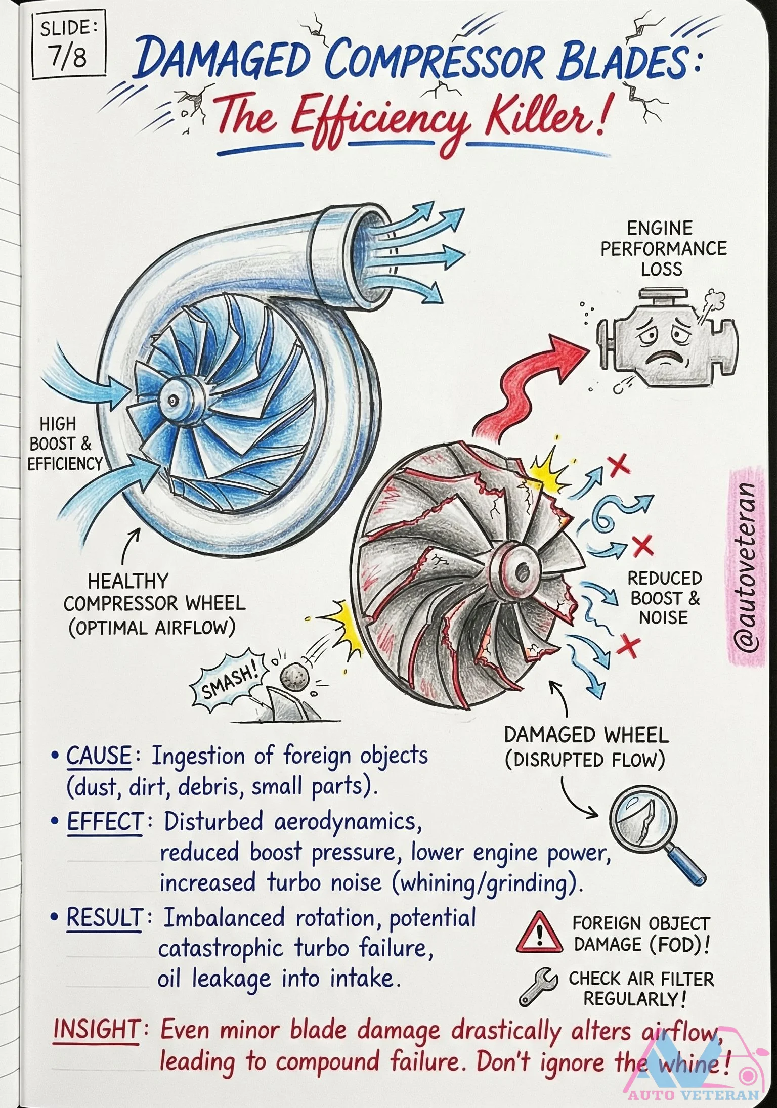
Turbo Compressor Blade Damage from Foreign Objects
When foreign object damage compromises turbocharger compressor blades, the aerodynamic disruption causes immediate performance degradation; reduced boost pressure, lower engine power output, and distinctive whining or grinding noises signal the imbalance. This condition can escalate to catastrophic turbo failure with oil ingestion into the intake system, making regular air filter inspection essential to prevent debris ingestion.
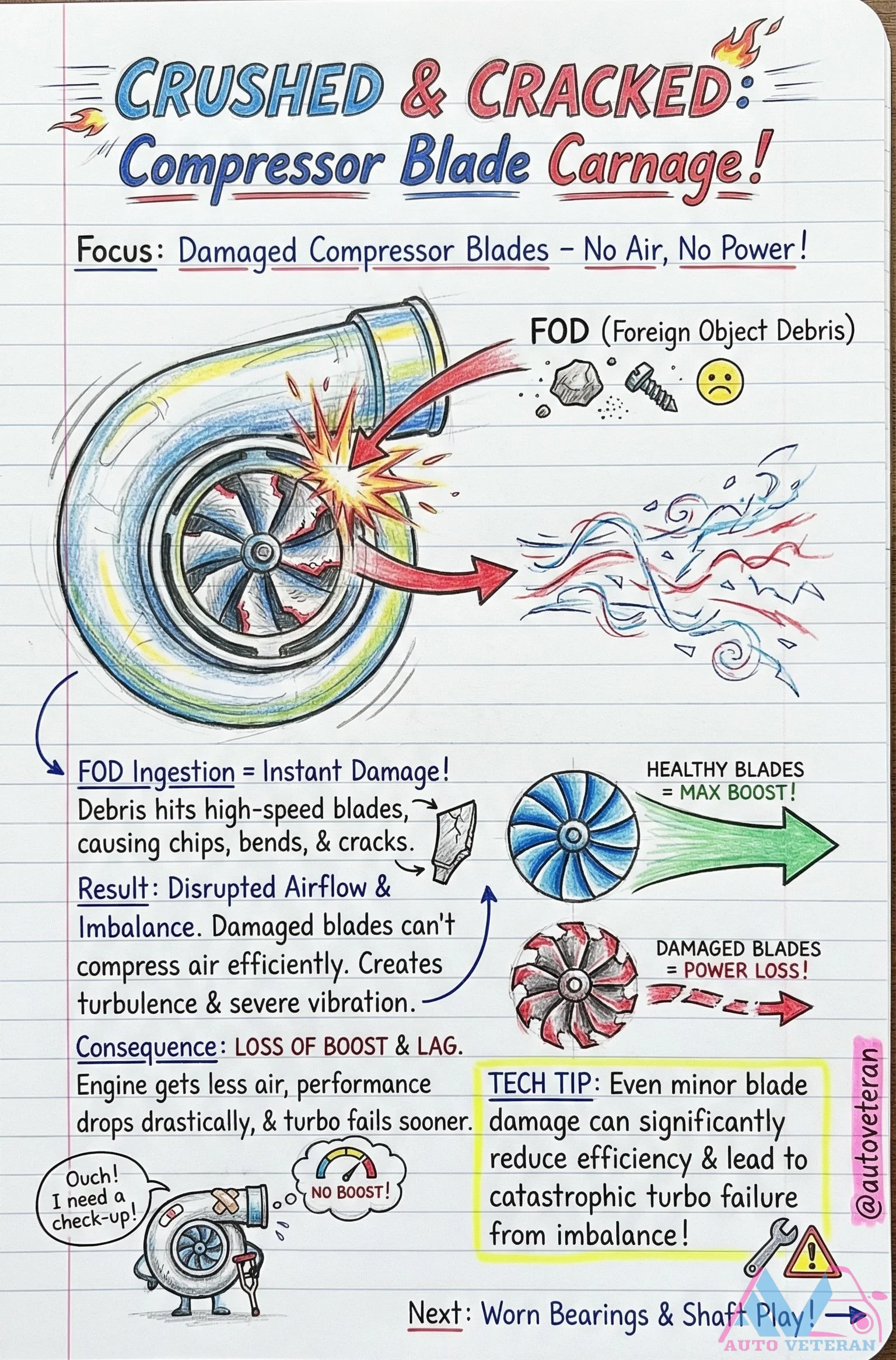
Turbo Compressor Blade FOD Damage Symptoms
When foreign object debris strikes the high speed compressor blades of a turbocharger, it creates immediate carnage with chips, bends, and cracks; this damage disrupts airflow, creates turbulence, and causes severe vibration from imbalance; the result is a significant loss of boost pressure, noticeable power lag, reduced engine performance, and eventual turbo failure from bearing and shaft wear due to the imbalance.
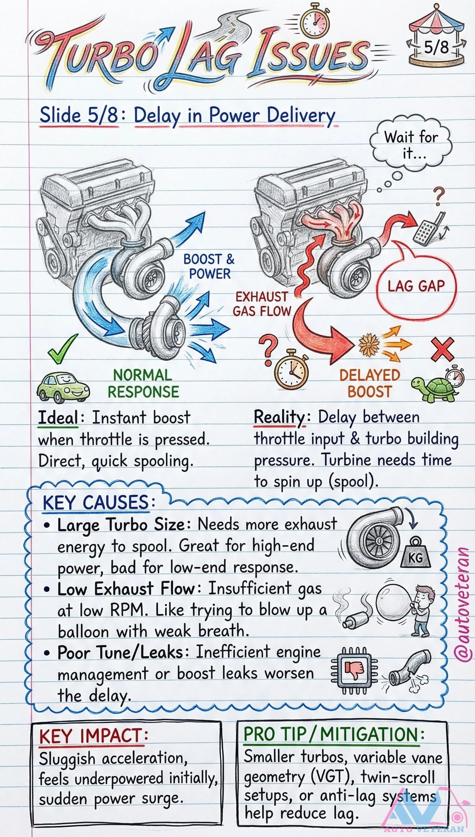
Turbo Lag Causes and Mitigation Strategies
Turbo lag occurs when there is a delay between throttle input and boost pressure delivery, creating a noticeable power gap during acceleration. This happens because the turbine requires time to spool up using exhaust gas flow. Key causes include large turbos that need more exhaust energy for high-end power but sacrifice low-end response, insufficient exhaust flow at low RPMs similar to trying to inflate a balloon with weak breath, and poor engine management or boost leaks that worsen the delay. The impact results in sluggish initial acceleration followed by a sudden power surge. Pro tips for mitigation involve using smaller turbos, variable vane geometry like VGT systems, twin-scroll designs, or anti-lag setups to reduce spool time and improve responsiveness.
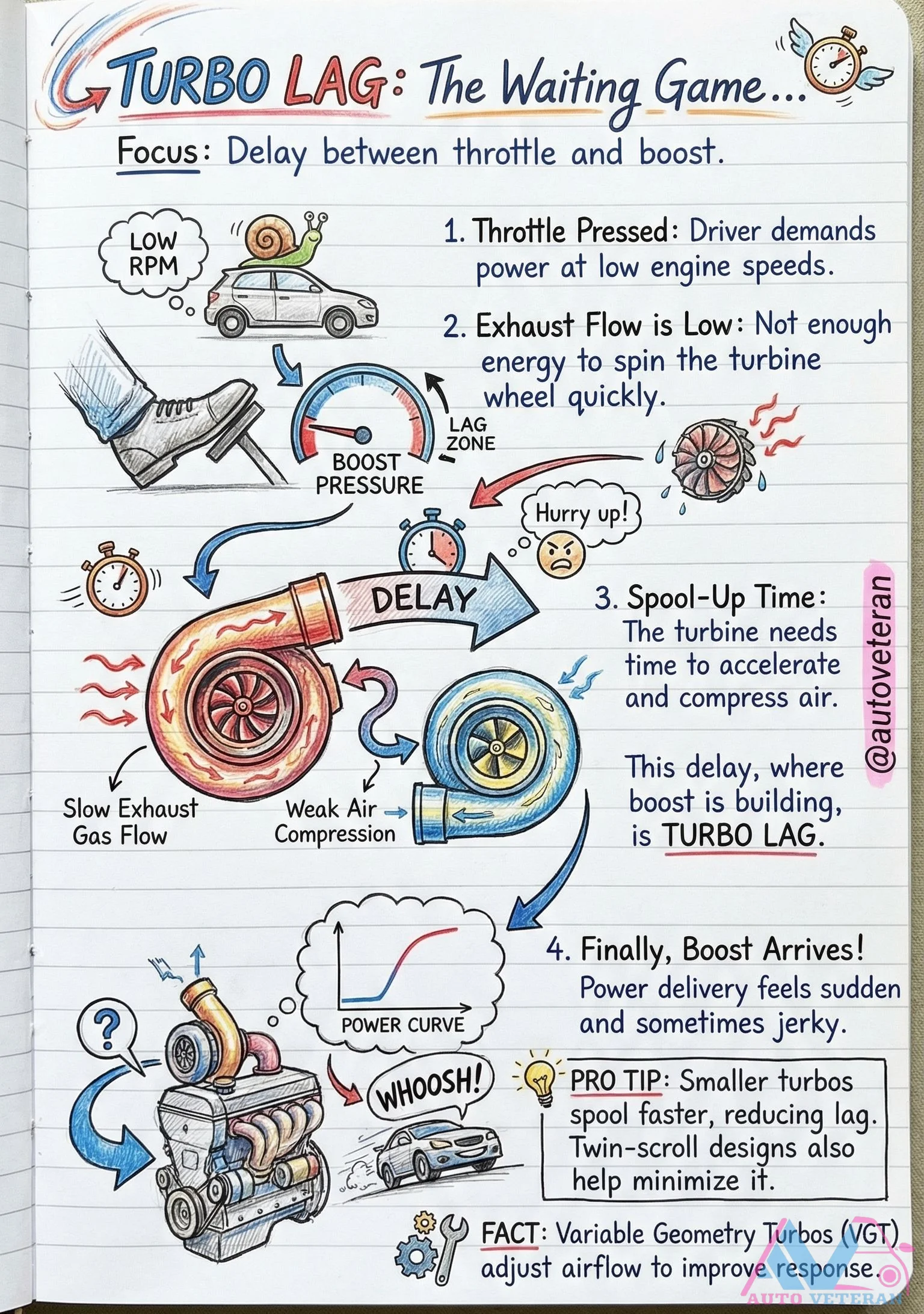
Turbo Lag Causes and Spool-Up Delay
Turbo lag occurs when there is a delay between throttle input and boost delivery, primarily at low engine RPMs where exhaust flow is insufficient to spin the turbine wheel quickly; this creates a lag zone where boost pressure builds slowly, resulting in sudden and sometimes jerky power delivery once spool-up completes. Smaller turbos reduce this delay by spooling faster, while twin-scroll designs and Variable Geometry Turbos (VGT) adjust airflow to improve throttle response and minimize waiting periods.
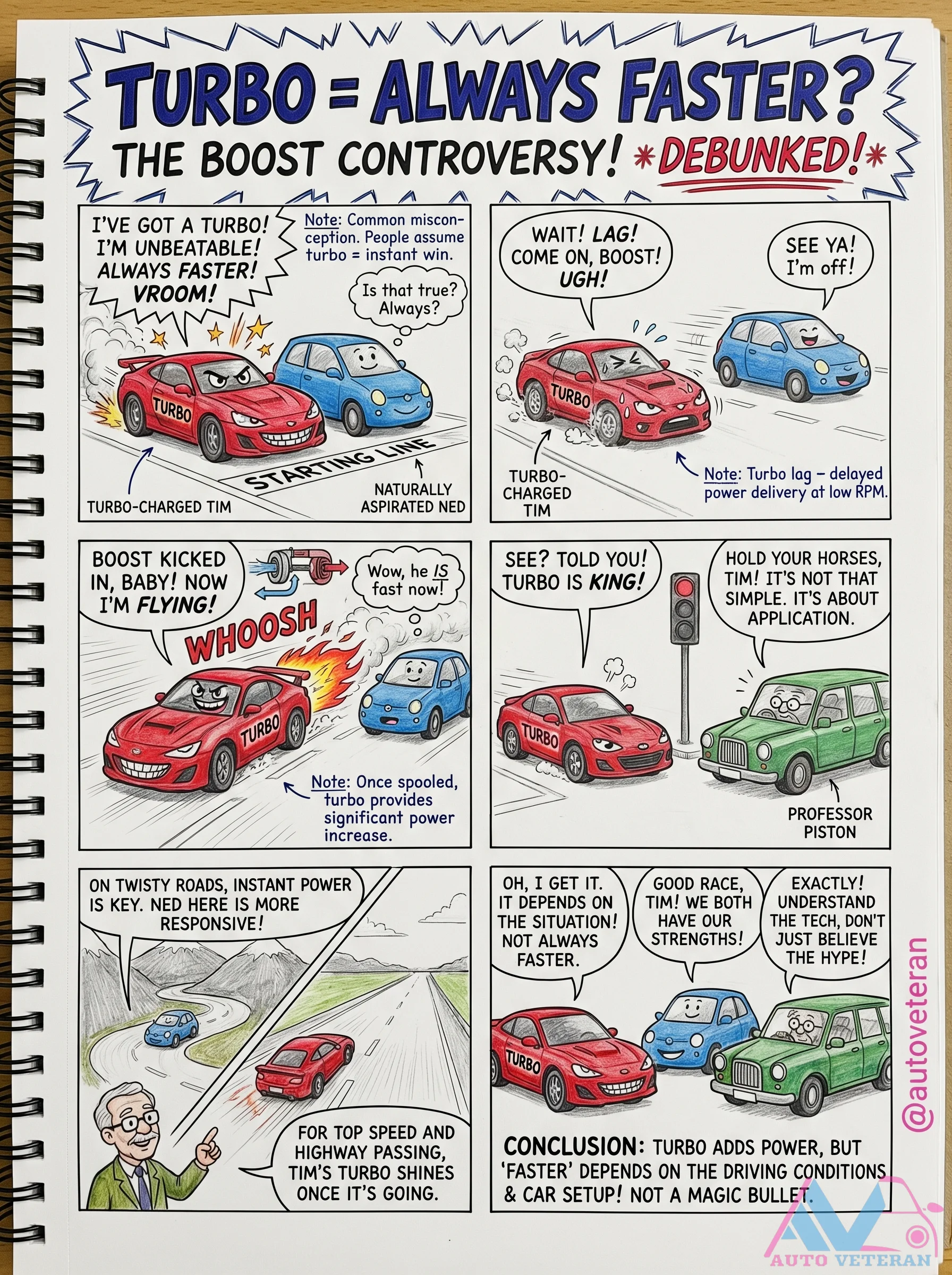
Turbo Lag vs Instant Power Application Myths
The debate over turbocharged versus naturally aspirated engines often centers on misconceptions about instant power delivery and overall speed. While turbo systems can provide significant power increases once spooled, they may suffer from lag at low RPMs, making them less responsive in certain driving conditions like twisty roads. Naturally aspirated engines offer more immediate throttle response, which can be crucial for applications requiring instant power. The truth is that neither is universally faster; performance depends on specific driving conditions, car setup, and intended use, such as top speed, highway passing, or responsive handling. Understanding these nuances helps debunk the hype that turbos are always superior, highlighting that each technology has its strengths tailored to different scenarios.
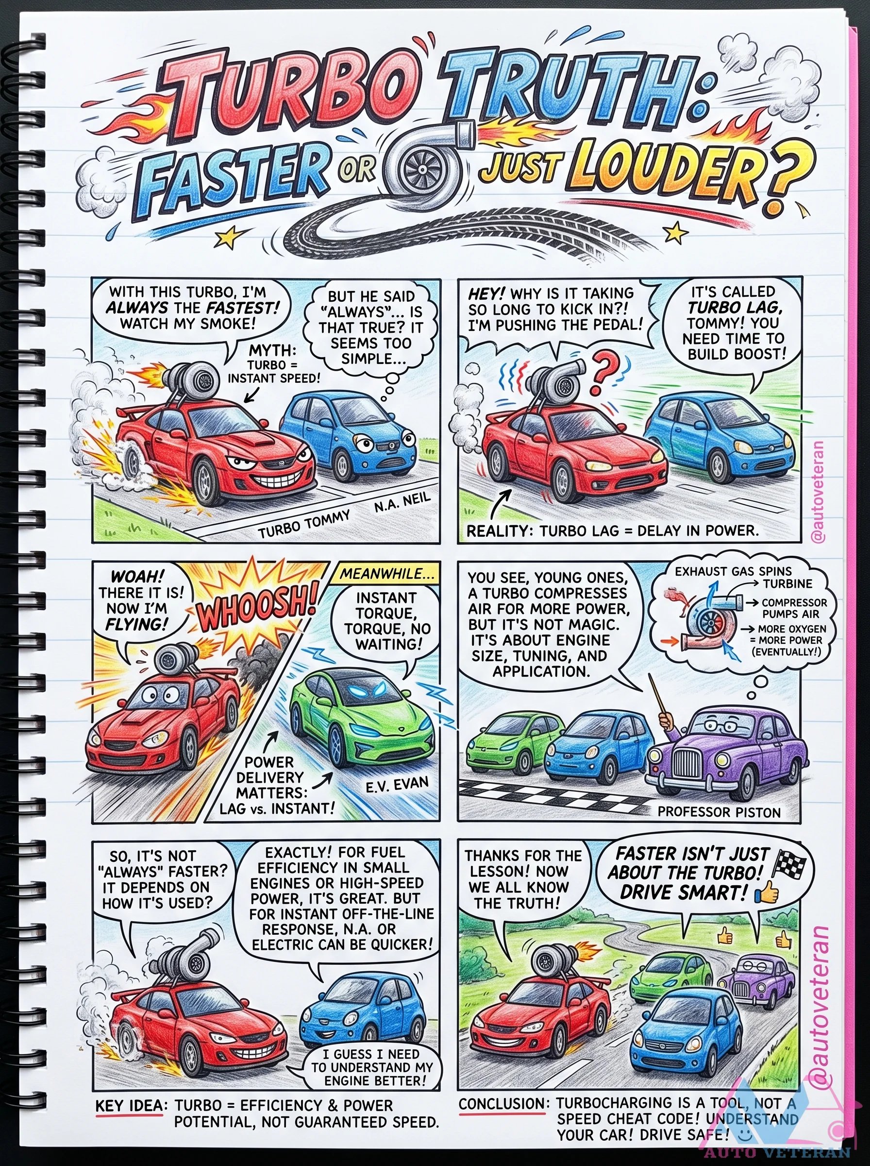
Turbo Lag vs Instant Power Reality
The common myth that turbochargers deliver instant speed is debunked through a detailed explanation of turbo lag, the delay in power delivery while exhaust gases spin the turbine to compress air for more oxygen and eventual boost. This reality contrasts with the misconception of magic speed, highlighting how factors like engine size, tuning, and application affect power delivery, making turbocharging a tool for efficiency and potential rather than a guaranteed cheat code for immediate acceleration.
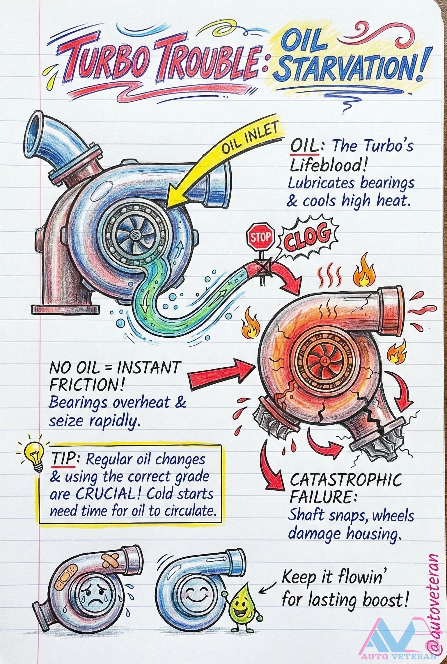
Turbo Oil Starvation Causes Catastrophic Failure
Oil starvation in turbochargers leads to instant friction, where bearings overheat and seize rapidly; this can cause catastrophic failure with the shaft snapping and wheels damaging the housing. Regular oil changes with the correct grade and allowing time for oil circulation during cold starts are crucial to prevent this, as oil lubricates bearings and cools high heat, acting as the turbo's lifeblood.
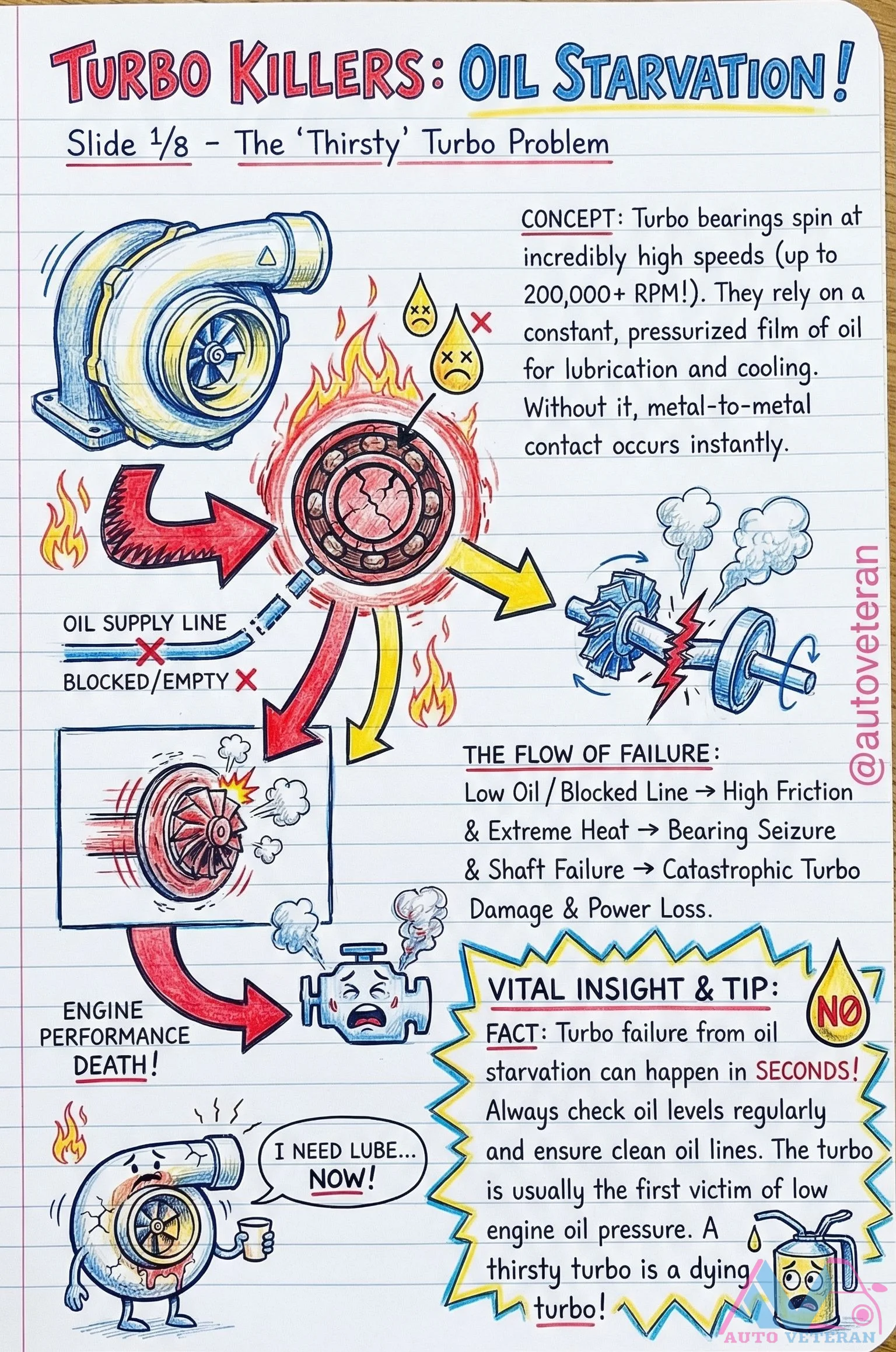
Turbo Oil Starvation Flow of Failure
When a turbocharger's oil supply line becomes blocked or empty, the bearings that spin at over 200,000 RPM lose their critical lubrication and cooling; this leads to immediate metal to metal contact, high friction, extreme heat, shaft seizure, and catastrophic turbo damage with complete power loss. A thirsty turbo is a dying turbo that can fail in seconds due to low engine oil pressure, making regular oil level checks and clean oil lines essential for prevention.
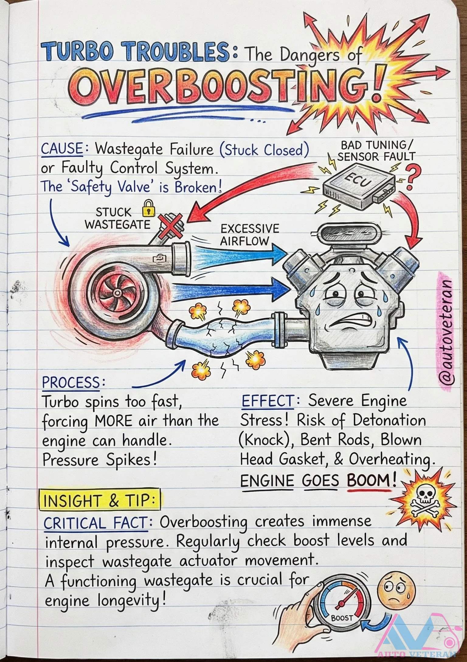
Turbo Overboost Dangers from Wastegate Failure
When a turbocharger's wastegate fails stuck closed or the control system malfunctions, the turbo spins uncontrollably fast, forcing excessive airflow into the engine. This creates dangerous pressure spikes that can lead to engine detonation, bent connecting rods, blown head gaskets, severe overheating, and catastrophic engine failure. Regular monitoring of boost levels and inspection of wastegate actuator movement are critical preventive measures to protect engine longevity.
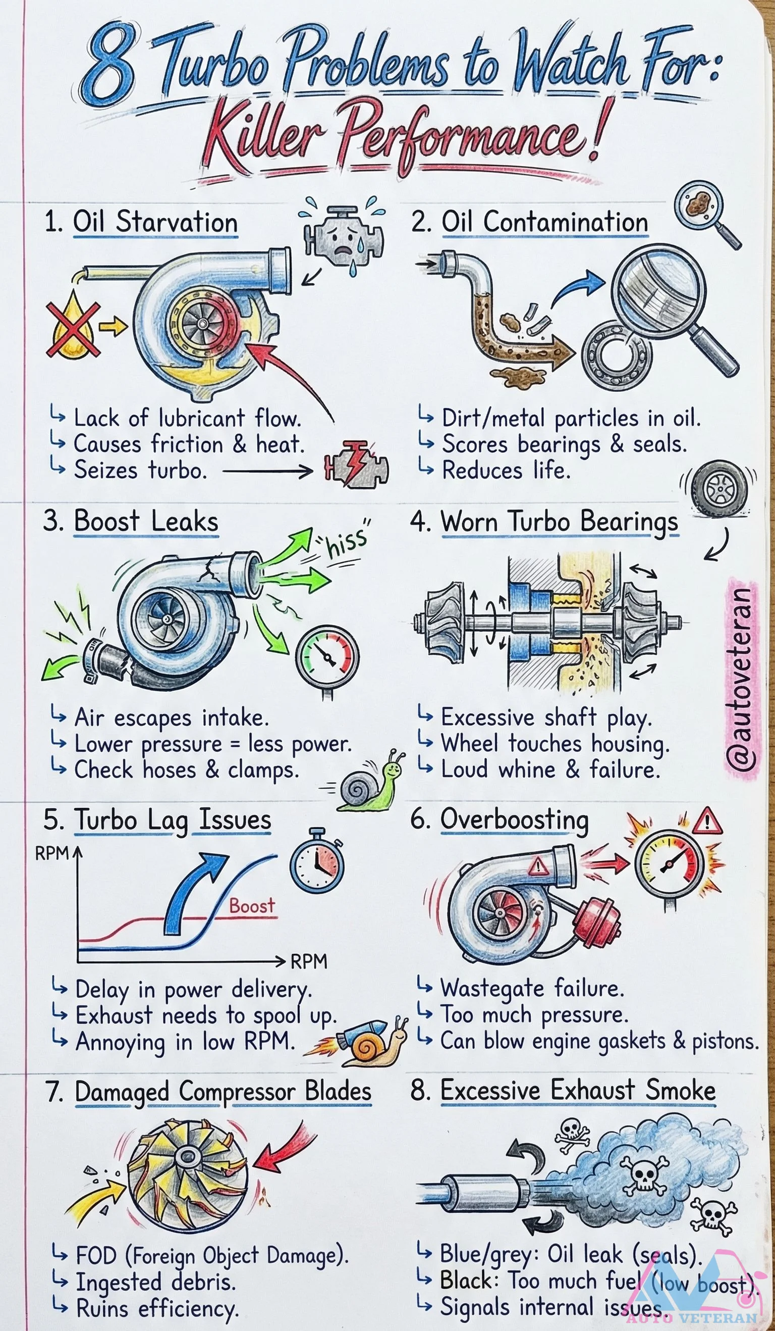
Turbo Problems: Oil Starvation and Contamination
Oil starvation and contamination are critical turbocharger issues that can lead to catastrophic failure. Lack of lubricant flow causes friction and heat buildup, scoring bearings and seals, while dirt or metal particles in the oil accelerate wear, potentially seizing the turbo and drastically reducing its lifespan. These problems often manifest through symptoms like excessive shaft play, loud whining noises, or eventual complete failure, requiring immediate attention to prevent engine damage.
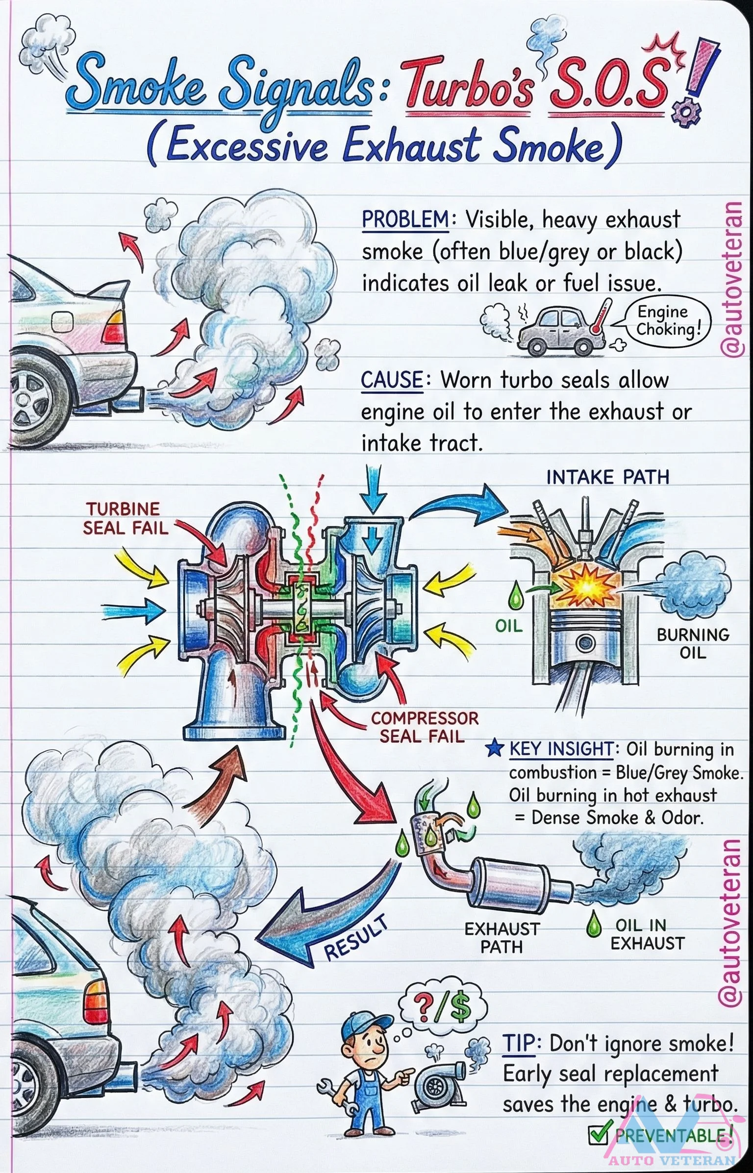
Turbo Seal Failure Causes Blue or Grey Exhaust Smoke
When turbocharger seals fail, engine oil can leak into either the intake or exhaust system, creating distinct smoke signals that demand immediate attention. Blue smoke indicates oil burning directly in the combustion chamber through the intake path, while dense grey smoke with odor results from oil burning in the hot exhaust system through the turbine seal. This preventable condition can lead to engine choking and severe damage if ignored, making early seal replacement crucial for preserving both your turbocharger and engine.