Interactive Explorer
ABS (Anti-lock Braking System)
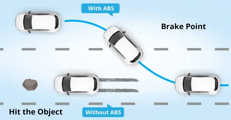
The ABS is a critical safety feature that prevents the wheels from locking up during sudden or hard braking. It uses sensors and electronic control to modulate brake pressure, helping the driver maintain steering control. ABS greatly reduces the risk of skidding, especially on wet or slippery roads.
ABS Hydraulic Unit and Electronic Module HECU Function
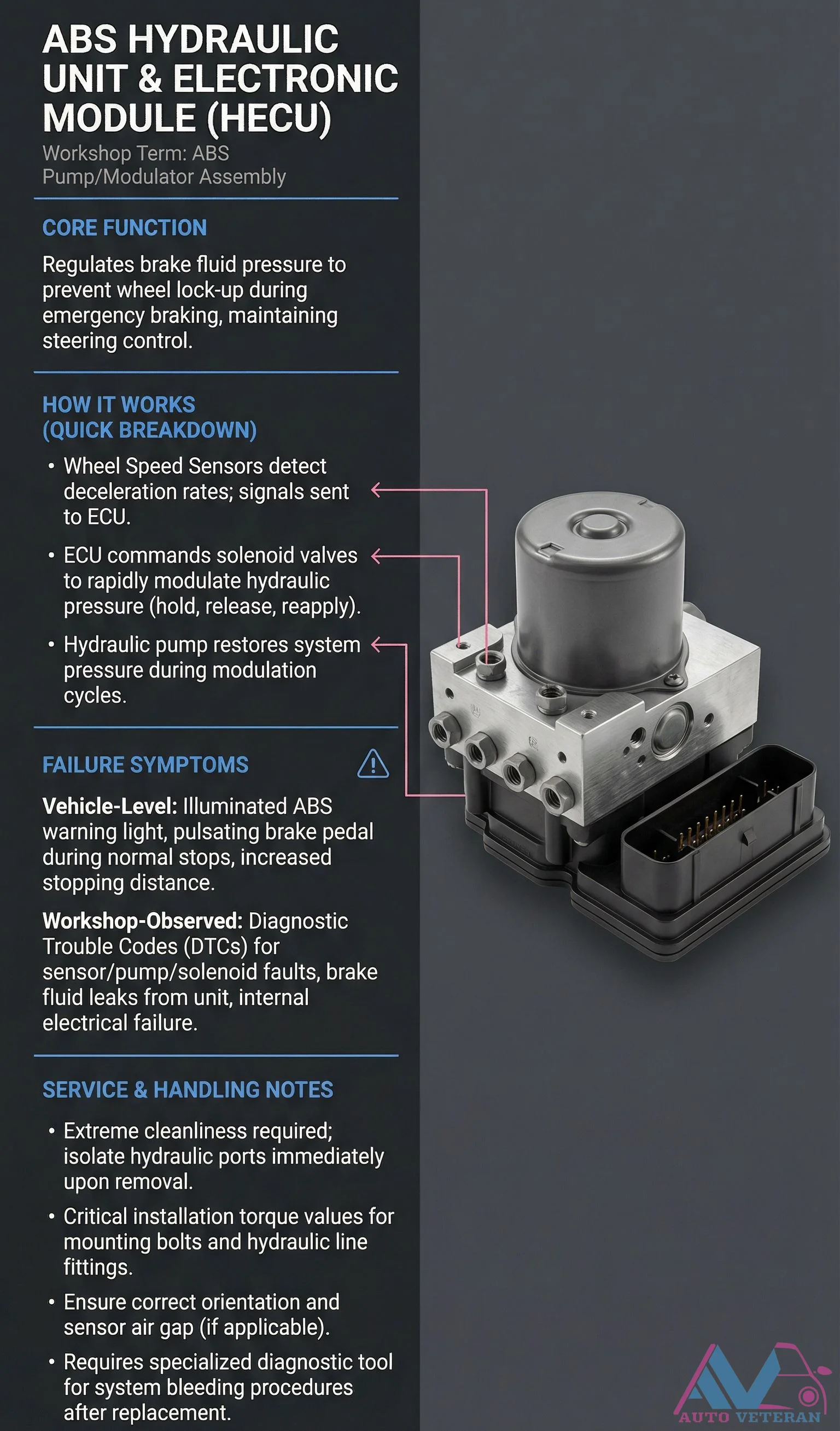
The ABS Hydraulic Unit and Electronic Module, known as the HECU or ABS pump modulator assembly, serves as the core regulator of brake fluid pressure to prevent wheel lock up during emergency braking while maintaining steering control. It operates through wheel speed sensors detecting deceleration rates and sending signals to the ECU, which then commands solenoid valves to rapidly modulate hydraulic pressure through hold, release, and reapply cycles. A hydraulic pump restores system pressure during these modulation cycles. Failure symptoms include an illuminated ABS warning light, pulsating brake pedal during normal stops, increased stopping distance, and diagnostic trouble codes for sensor, pump, or solenoid faults. Service requires extreme cleanliness, immediate isolation of hydraulic ports upon removal, adherence to critical torque values for mounting bolts and hydraulic line fittings, correct orientation and sensor air gap, and specialized diagnostic tools for system bleeding procedures after replacement.
ABS Module HCU Core Function and Failure Symptoms
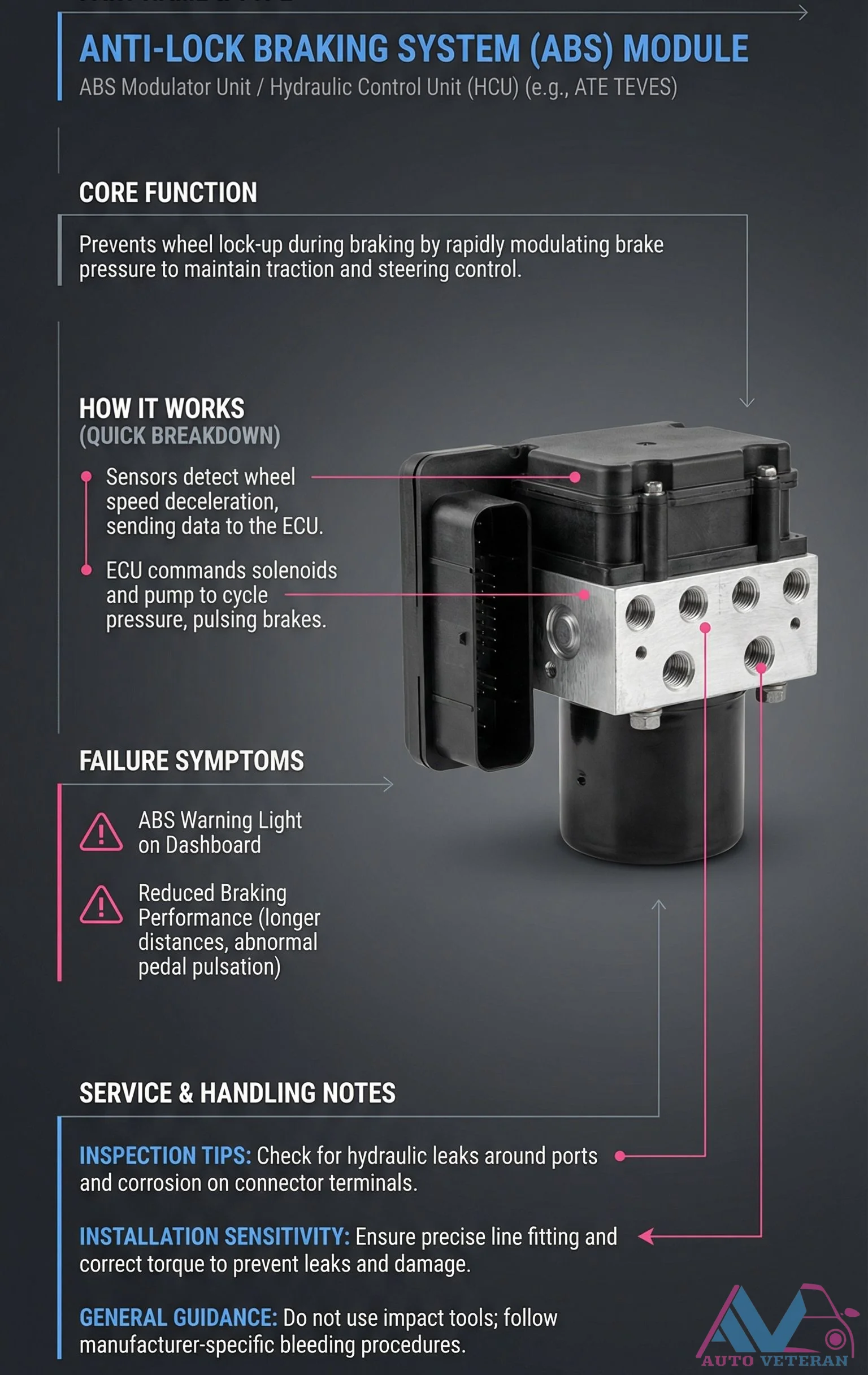
The Anti-lock Braking System module, also known as the Hydraulic Control Unit or ABS modulator, serves the critical function of preventing wheel lock-up during braking by rapidly modulating brake pressure to maintain traction and steering control. This system operates through wheel speed sensors that detect deceleration, sending data to the ECU which then commands solenoids and pumps to cycle pressure, creating the characteristic brake pulsing. When this system fails, drivers typically experience the ABS warning light illuminating on the dashboard, reduced braking performance with longer stopping distances, and abnormal pedal pulsation. Proper service requires careful inspection for hydraulic leaks around ports and corrosion on connector terminals, precise line fitting with correct torque specifications to prevent leaks, avoidance of impact tools during installation, and adherence to manufacturer specific bleeding procedures.
ABS Sensor Working Principle Step by Step
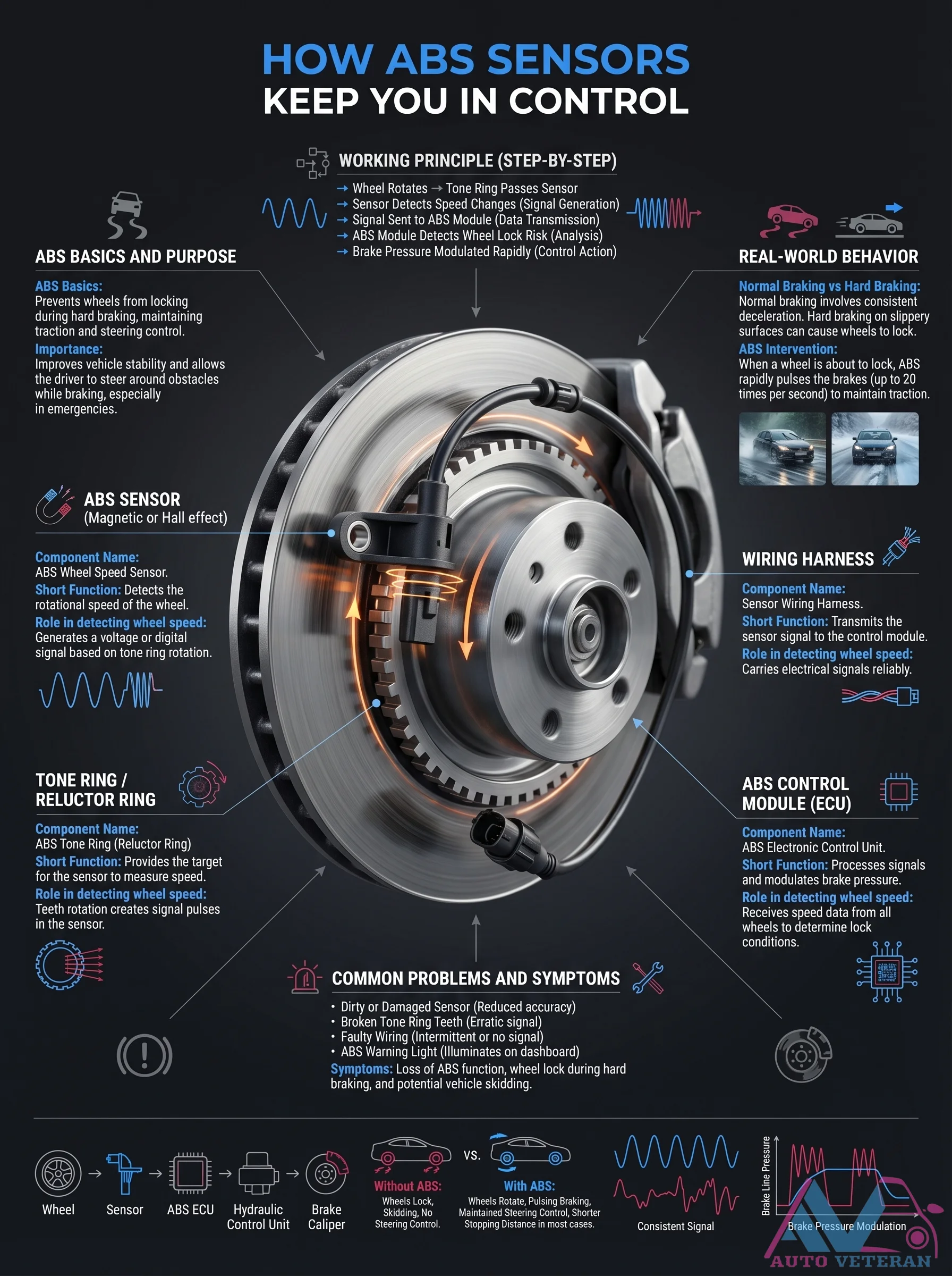
The ABS system operates through a precise sequence where wheel rotation causes a tone ring to pass the sensor, generating speed signals transmitted to the ABS module; this module analyzes data to detect wheel lock risk and modulates brake pressure up to 20 times per second, maintaining traction and steering control during hard braking while preventing skidding.
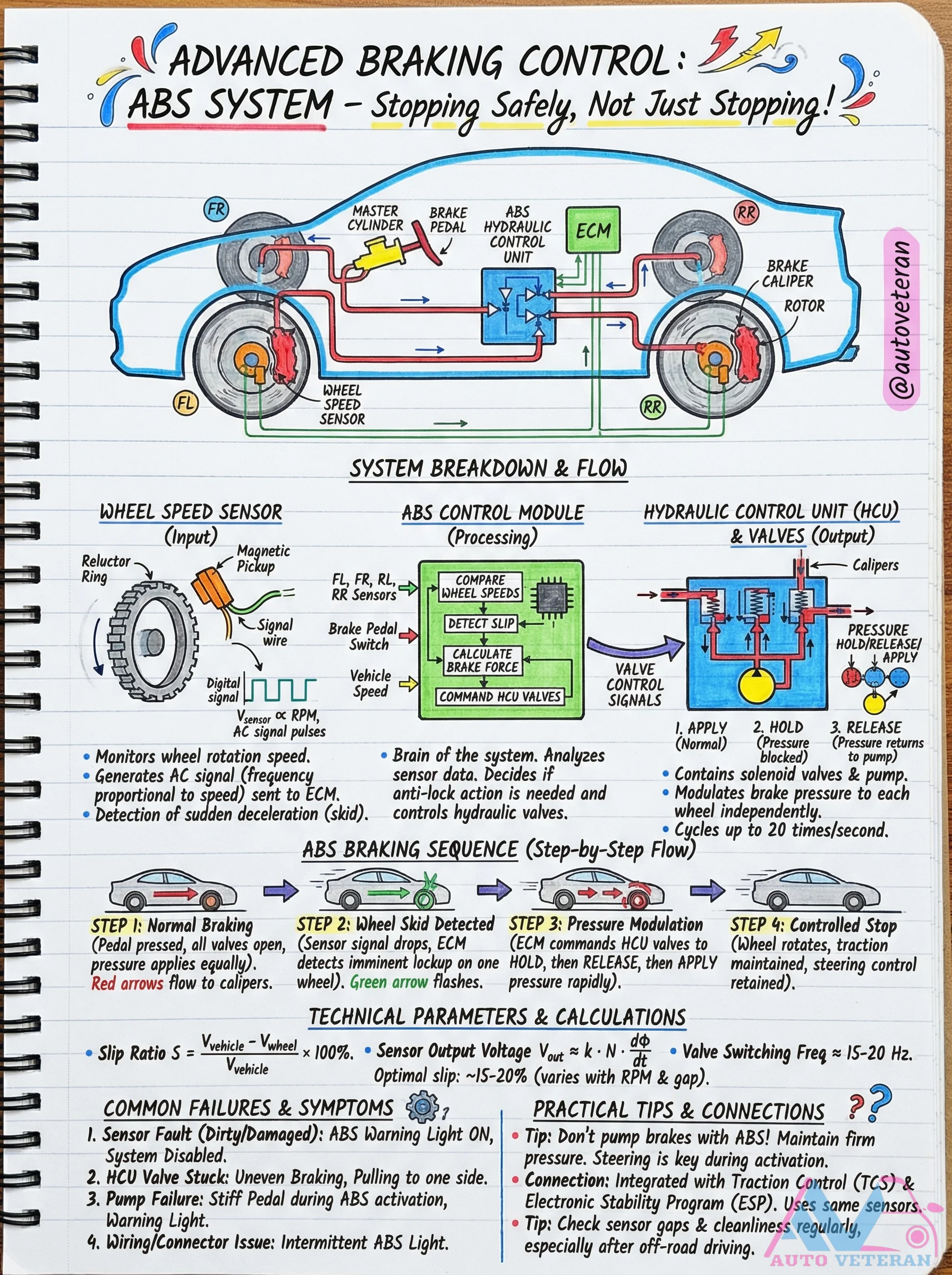
ABS System Breakdown and Flow Diagram
This detailed breakdown illustrates the complete ABS system architecture and operational flow, from wheel speed sensors detecting rotation to the hydraulic control unit modulating brake pressure. The diagram shows how the ABS control module processes sensor signals, calculates slip ratios, and commands solenoid valves to cycle up to 20 times per second during activation. It highlights the integration with traction control and electronic stability systems, while explaining technical parameters like optimal slip ratios of 15-20% and common failure symptoms including sensor faults and valve issues.
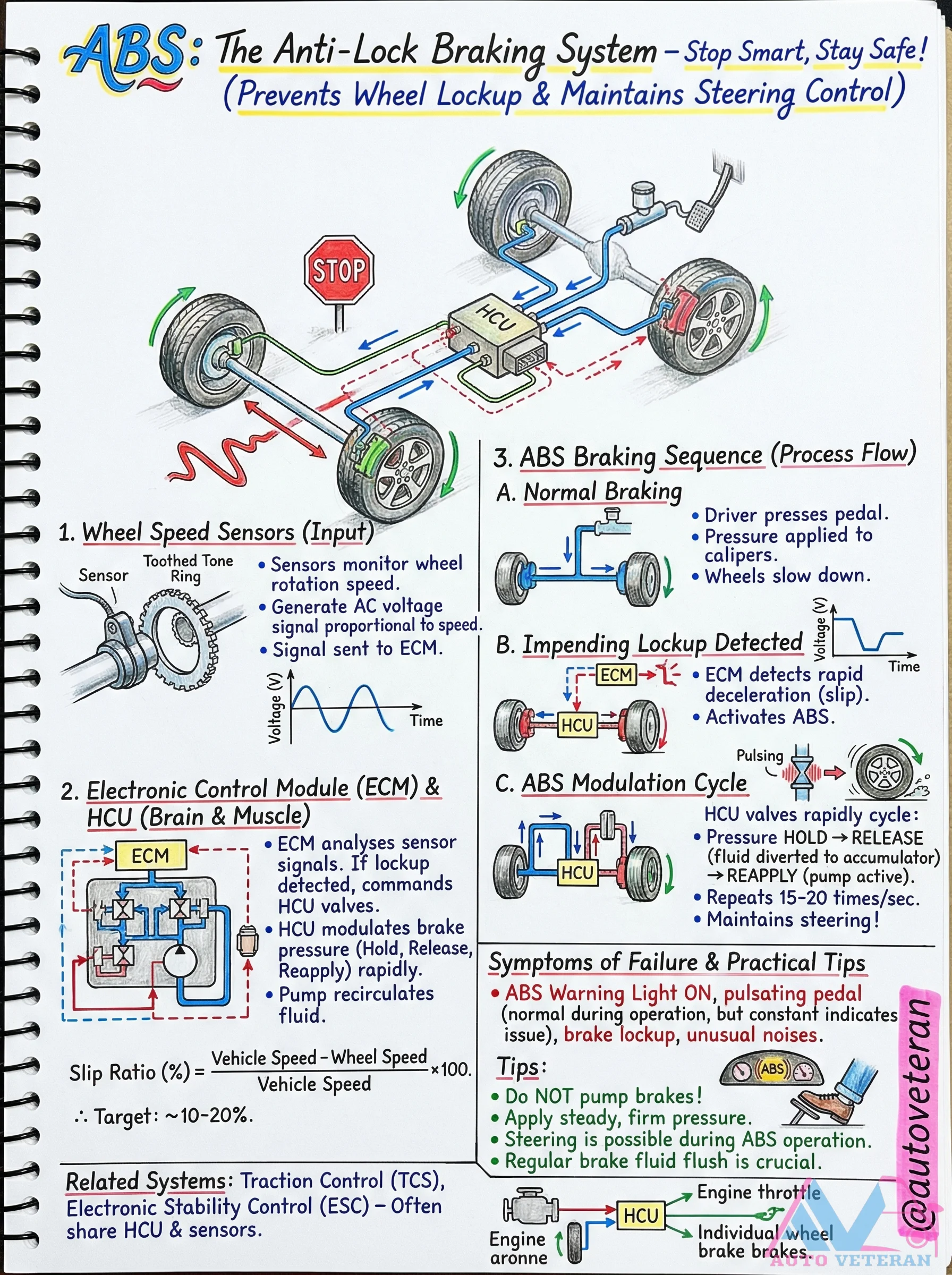
ABS System Process Flow and Failure Symptoms
The Anti-Lock Braking System operates through a precise sequence of events, beginning with wheel speed sensors monitoring rotation and generating AC voltage signals proportional to speed. When the Electronic Control Module detects impending wheel lockup by analyzing rapid deceleration, it commands the Hydraulic Control Unit to modulate brake pressure through rapid hold, release, and reapply cycles that repeat 15 to 20 times per second. During normal ABS operation, you'll feel a pulsating brake pedal as the system maintains optimal slip ratios between 10 and 20 percent. Failure symptoms include the ABS warning light remaining constantly illuminated, actual brake lockup during hard stops, unusual hydraulic noises, and loss of steering control during emergency braking. Practical maintenance involves regular brake fluid flushes and avoiding the instinct to pump brakes during ABS activation, as this interferes with the system's rapid modulation capability. The ABS system shares components with Traction Control and Electronic Stability Control systems, often utilizing the same HCU and wheel speed sensors for coordinated vehicle stability management.
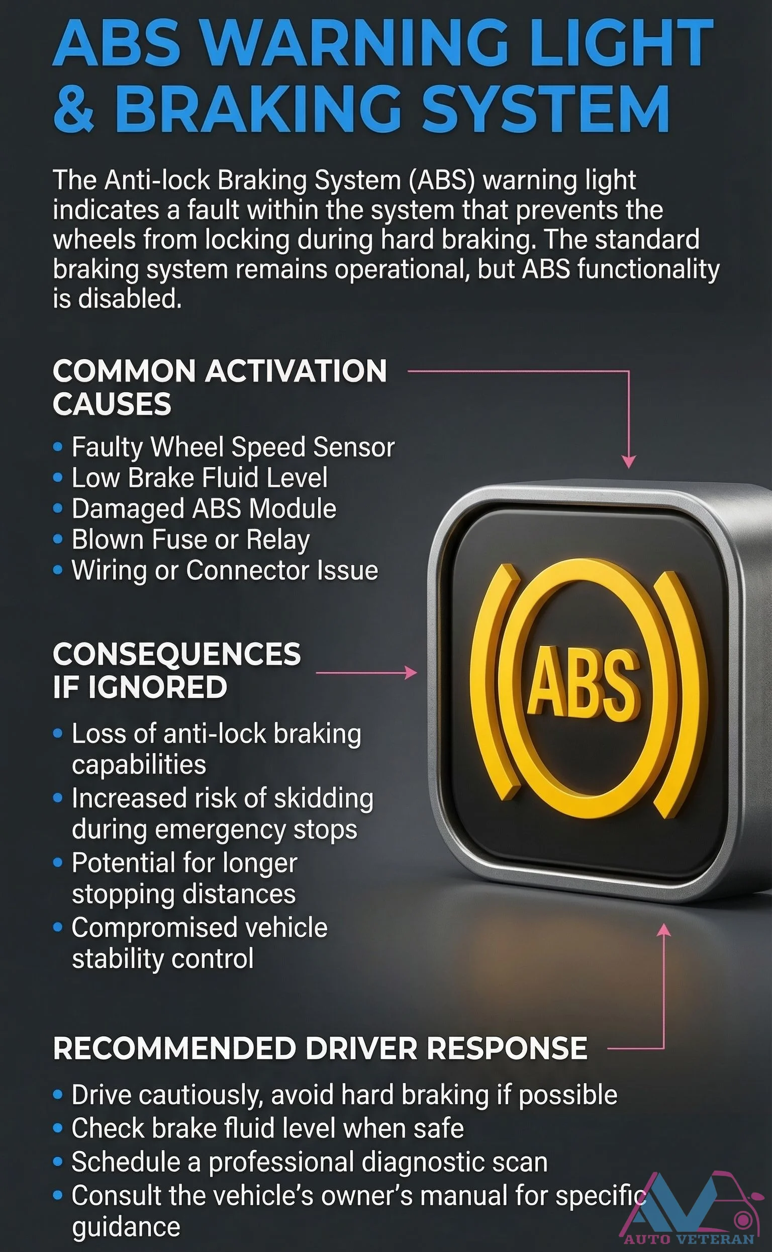
ABS Warning Light Causes, Consequences, and Driver Response
When the ABS warning light illuminates on your dashboard, it signals a fault within the Anti-lock Braking System that disables its wheel-lock prevention during hard braking. Common activation causes include a faulty wheel speed sensor, low brake fluid level, damaged ABS module, or blown fuse and wiring issues. Ignoring this warning leads to loss of anti-lock braking capabilities, increased skidding risk during emergency stops, longer stopping distances, and compromised vehicle stability control. The recommended driver response involves driving cautiously while avoiding hard braking, checking brake fluid levels when safe, scheduling a professional diagnostic scan, and consulting the vehicle's owner's manual for specific guidance.
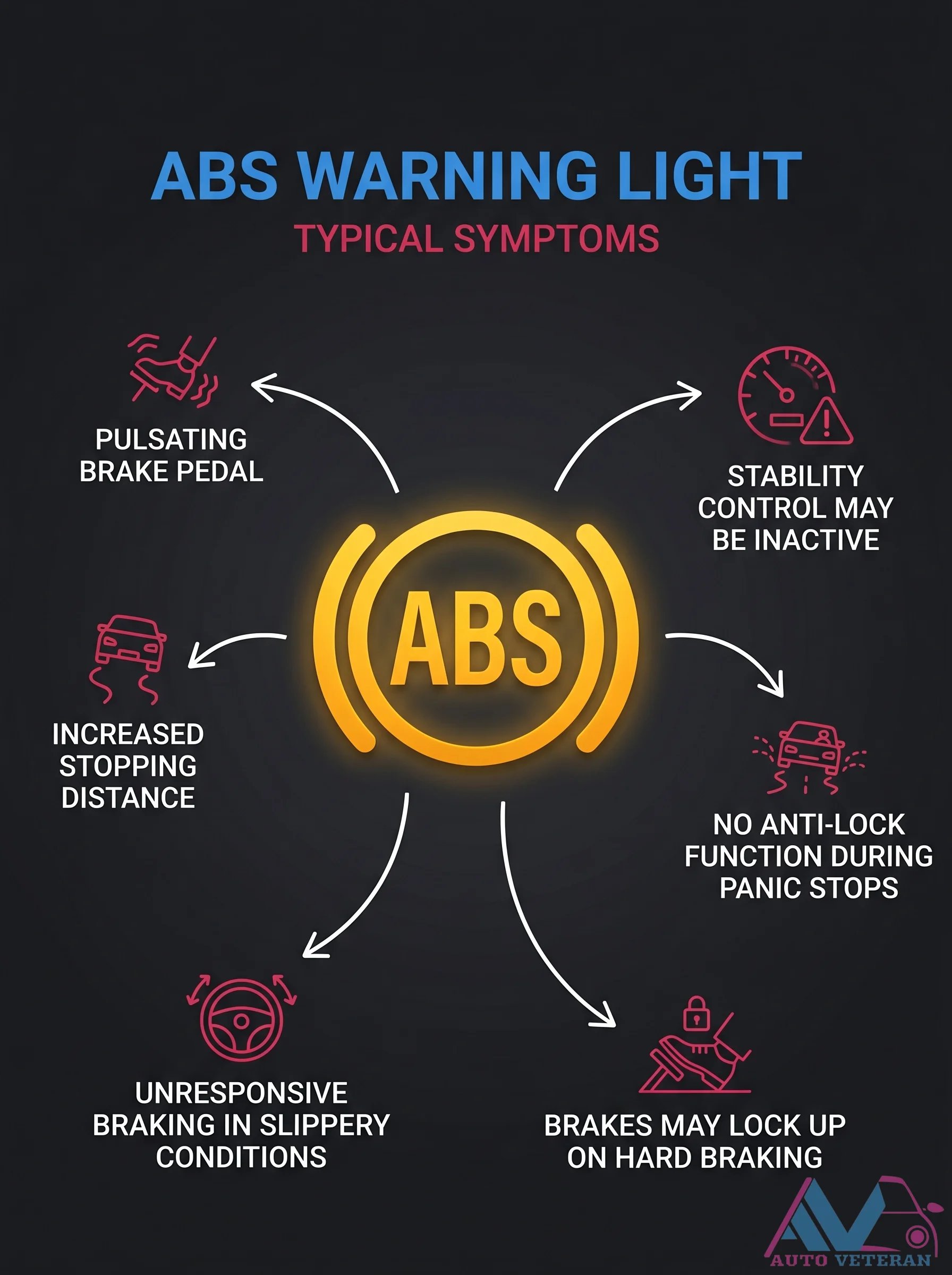
ABS Warning Light Symptoms
When your ABS warning light illuminates, you may experience a pulsating brake pedal, stability control becoming inactive, increased stopping distances, and a lack of anti-lock function during panic stops. In slippery conditions, brakes can lock up on hard braking, making the system unresponsive.
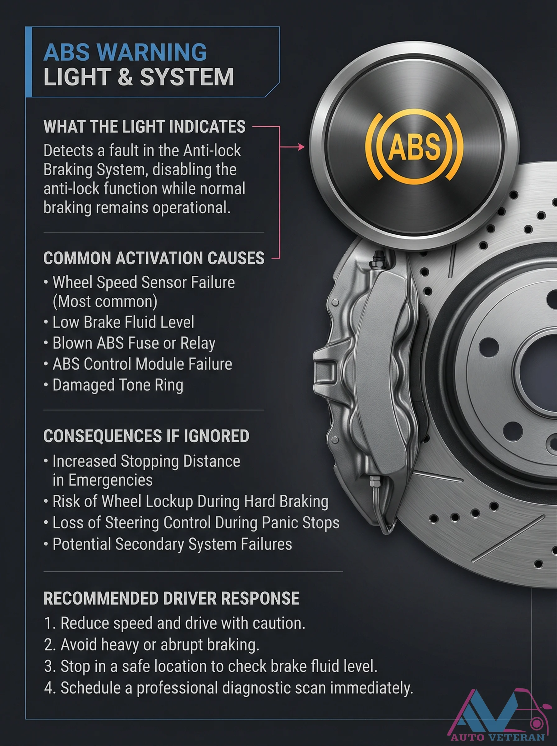
ABS Warning Light System Fault Causes and Consequences
When the ABS warning light illuminates on your dashboard, it signals a detected fault in the Anti-lock Braking System that disables anti-lock functionality while preserving normal braking. This condition typically arises from common issues like wheel speed sensor failure, low brake fluid levels, blown fuses or relays, ABS control module malfunctions, or damaged tone rings. Ignoring this warning increases stopping distances during emergency situations, raises the risk of wheel lockup during hard braking, compromises steering control during panic stops, and may lead to secondary system failures. Drivers should immediately reduce speed, exercise caution, avoid abrupt braking maneuvers, check brake fluid levels in a safe location, and schedule professional diagnostic scanning to address the underlying issue.
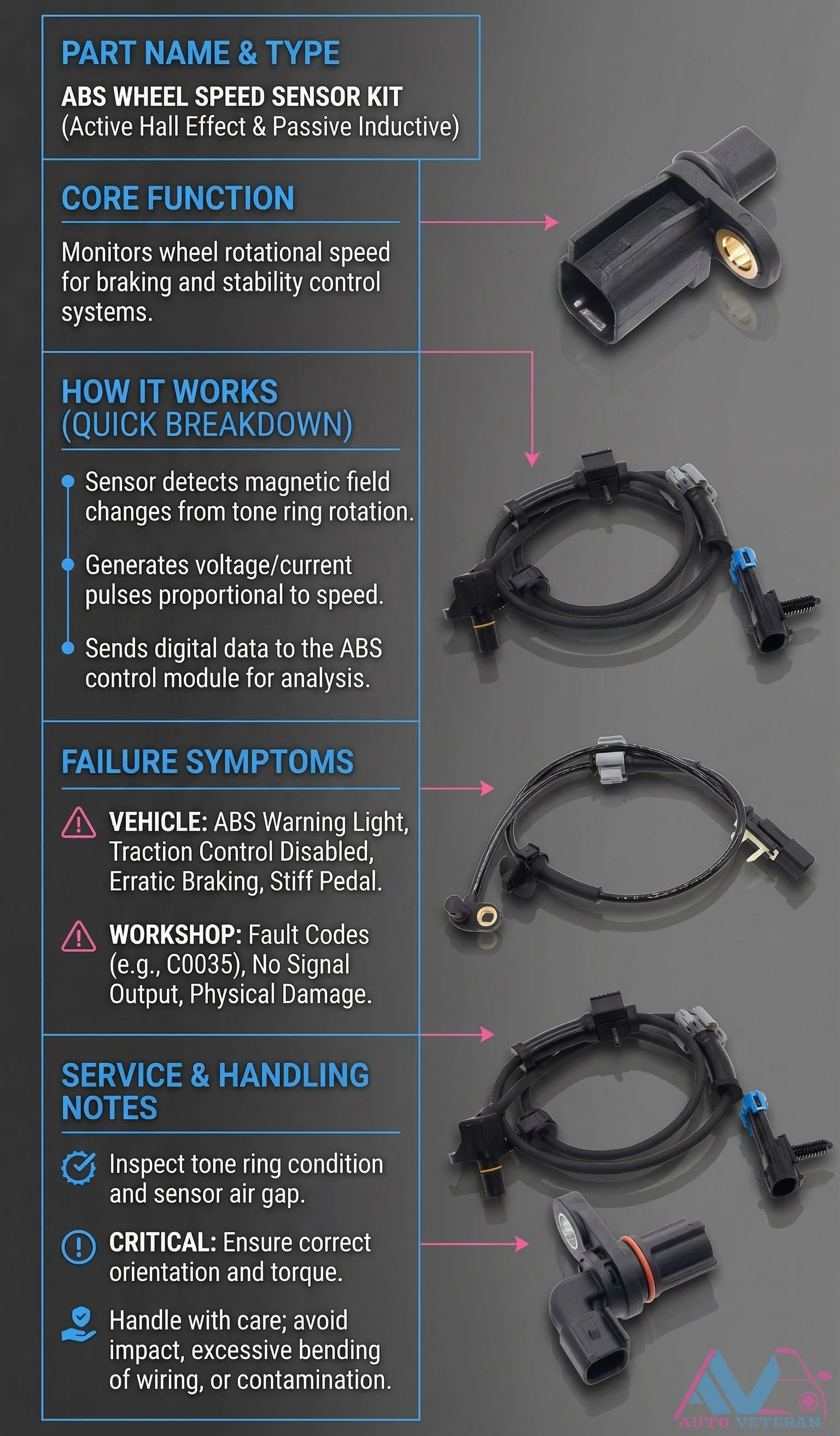
ABS Wheel Speed Sensor Failure Symptoms and Diagnosis
When an ABS wheel speed sensor fails, whether it's an active Hall effect or passive inductive type, your vehicle's braking and stability control systems lose critical data. The ABS warning light illuminates, traction control becomes disabled, and braking may feel erratic or produce a stiff pedal. In the workshop, technicians diagnose these issues by checking for fault codes like C0035, verifying signal output, and inspecting for physical damage. Proper service requires examining the tone ring condition, maintaining correct sensor air gap, ensuring proper orientation and torque during installation, and handling the sensor carefully to avoid impact, excessive wiring bending, or contamination.
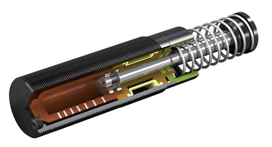
Absorption Shock Absorber (Shock)
A hydraulic device in the suspension system that dampens oscillations and controls the up-and-down movement of the wheels over road irregularities. Shocks contain hydraulic fluid and use valves and pistons to convert kinetic energy from wheel movement into heat energy, providing a smoother ride and maintaining tire contact with the road.
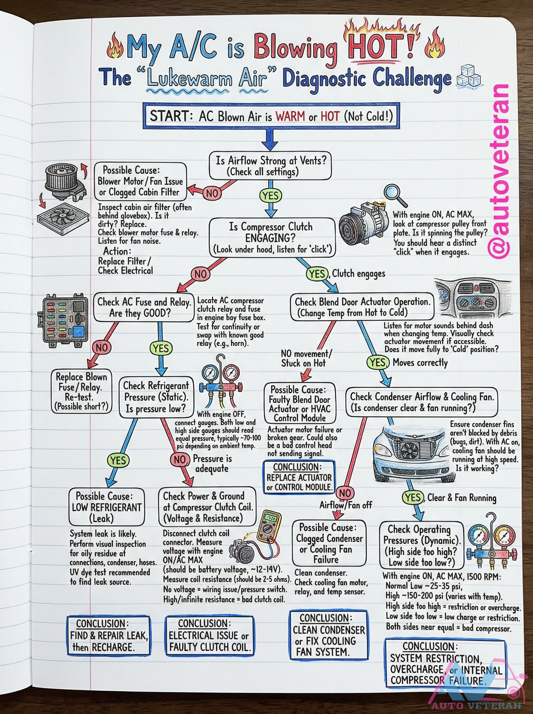
AC Blowing Hot Air Diagnostic Flowchart
When your car's air conditioning system blows warm or hot air instead of cold, this comprehensive diagnostic flowchart guides you through systematic troubleshooting. The process begins by checking cabin airflow with the blower motor and cabin filter, then moves to verifying compressor clutch engagement with its distinctive click sound. Next, examine blend door actuator operation by listening for motor sounds behind the dashboard during temperature changes. Electrical checks include testing the AC compressor clutch coil resistance, which should measure 2-5 ohms, and verifying proper voltage at the clutch connector. System pressure analysis requires checking both high and low side pressures with the engine running at 1500 RPM and AC on maximum; normal readings should show low side at 25-35 psi and high side at 150-200 psi depending on temperature. Additional steps involve inspecting condenser airflow, checking for refrigerant leaks with UV dye, and examining cooling fan operation. The flowchart concludes with specific failure conclusions including low refrigerant from leaks, electrical issues with the clutch coil, system restrictions, overcharge conditions, or internal compressor failure.
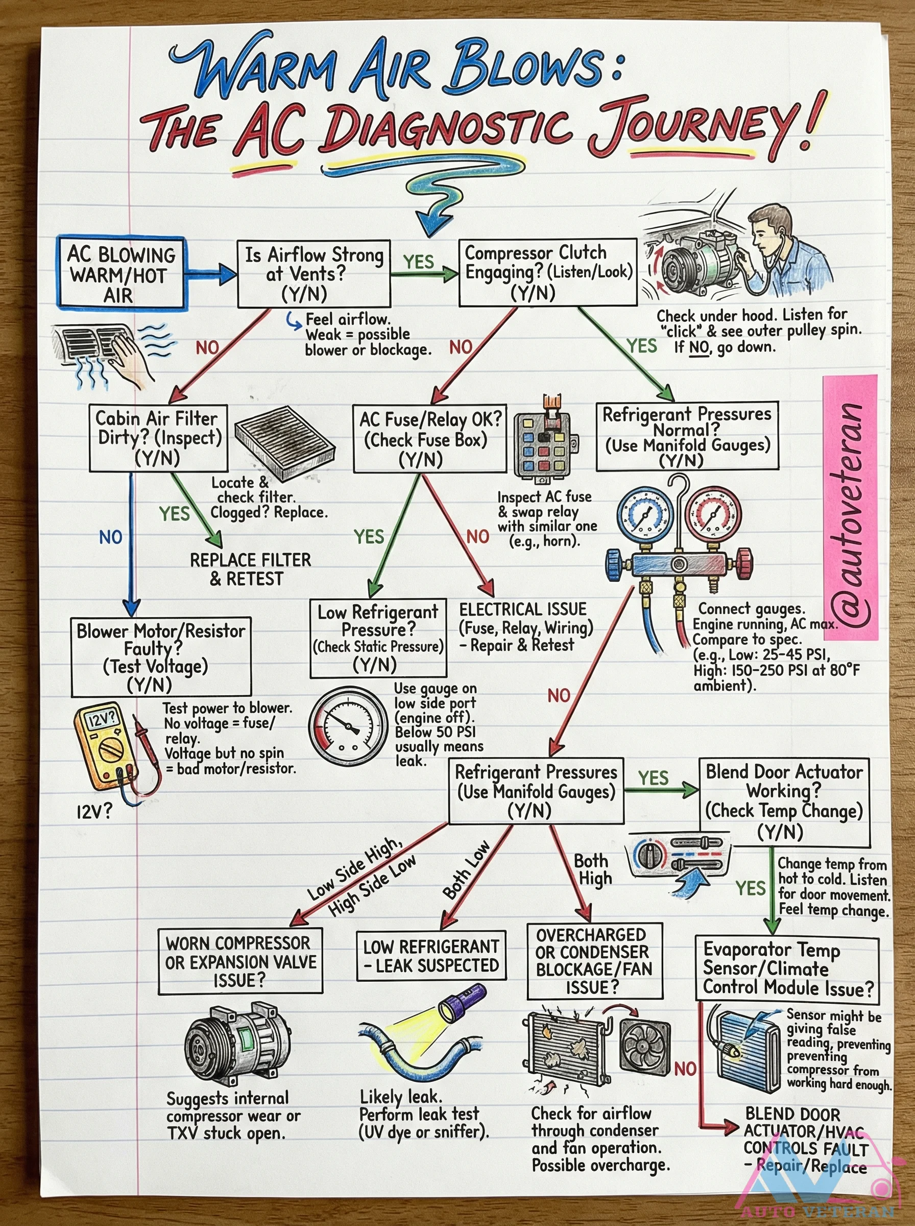
AC Blowing Warm Air Diagnostic Journey
When your vehicle's air conditioning system begins blowing warm or hot air at the vents, a systematic diagnostic approach is essential to pinpoint the root cause. Start by verifying strong airflow and listening for the compressor clutch engagement, then proceed through a logical sequence: check the cabin air filter for blockages, verify electrical components like fuses and relays, test refrigerant pressures using manifold gauges to identify low charge or overcharge conditions, and examine blower motor operation and blend door actuators. The diagnostic path branches based on findings, leading to specific issues like worn compressors, expansion valve blockages, evaporator temperature sensor failures, or climate control module faults, each requiring targeted repairs to restore proper cooling function.
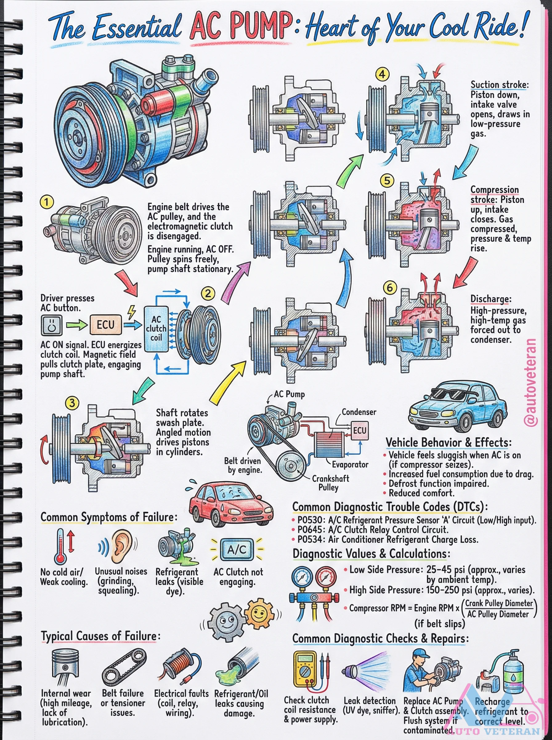
AC Compressor Operation, Failure Symptoms, and Diagnostics
The automotive AC compressor functions as the heart of your cooling system, driven by an engine belt and electromagnetic clutch. During operation, the suction stroke draws in low pressure refrigerant gas while the compression stroke increases pressure and temperature before discharge to the condenser. When the AC is off, the pulley spins freely while the shaft remains stationary; pressing the AC button signals the ECU to energize the clutch coil, creating a magnetic field that engages the pump shaft. Common failure symptoms include vehicle sluggishness, increased fuel consumption, impaired defrost function, unusual grinding or squealing noises, weak cooling, and visible refrigerant leaks. Diagnostic trouble codes include P0530 for refrigerant pressure sensor issues, P0534 for refrigerant charge loss, and P0645 for relay control circuit problems. Diagnostic checks involve measuring clutch coil resistance, verifying power supply, checking refrigerant levels with UV dye or sniffer tools, and ensuring proper belt tension. Typical causes of failure include internal wear from high mileage, belt or tensioner issues, electrical faults in coils or wiring, refrigerant or oil leaks causing lubrication problems, and contaminated systems requiring flushing and recharging.
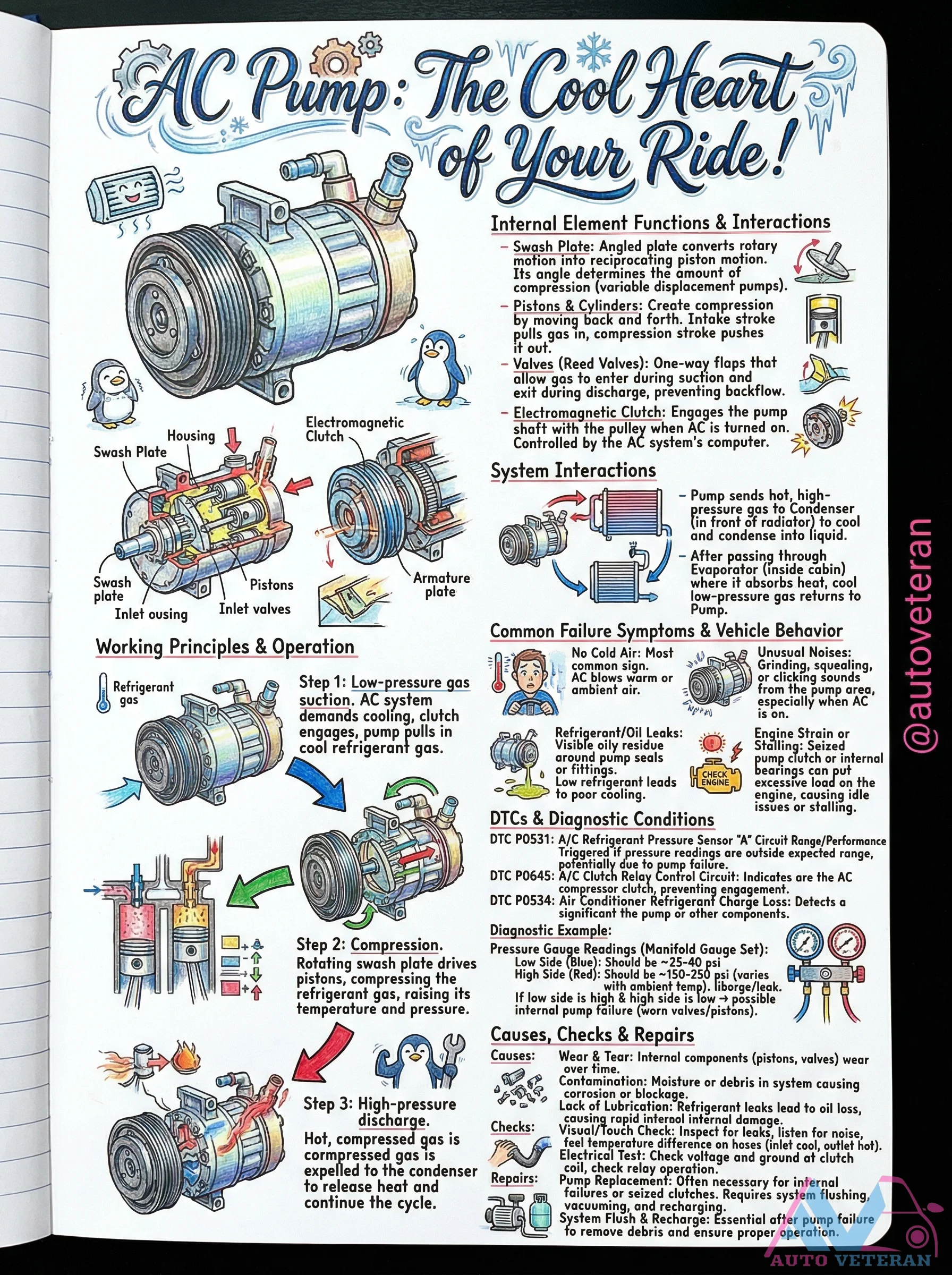
AC Compressor Swash Plate Failure Symptoms and Diagnosis
When the swash plate inside your vehicle's AC compressor wears or malfunctions, it fails to properly convert rotary motion into the reciprocating piston action needed for refrigerant compression. This results in insufficient cooling, unusual grinding or squealing noises from the pump, and potential engine idle issues due to excessive load. Diagnostic trouble codes like P0531 for refrigerant pressure sensor performance and P0645 for clutch relay circuit problems often accompany these failures, indicating a need for thorough checks including visual inspection for leaks and electrical testing of the clutch system.
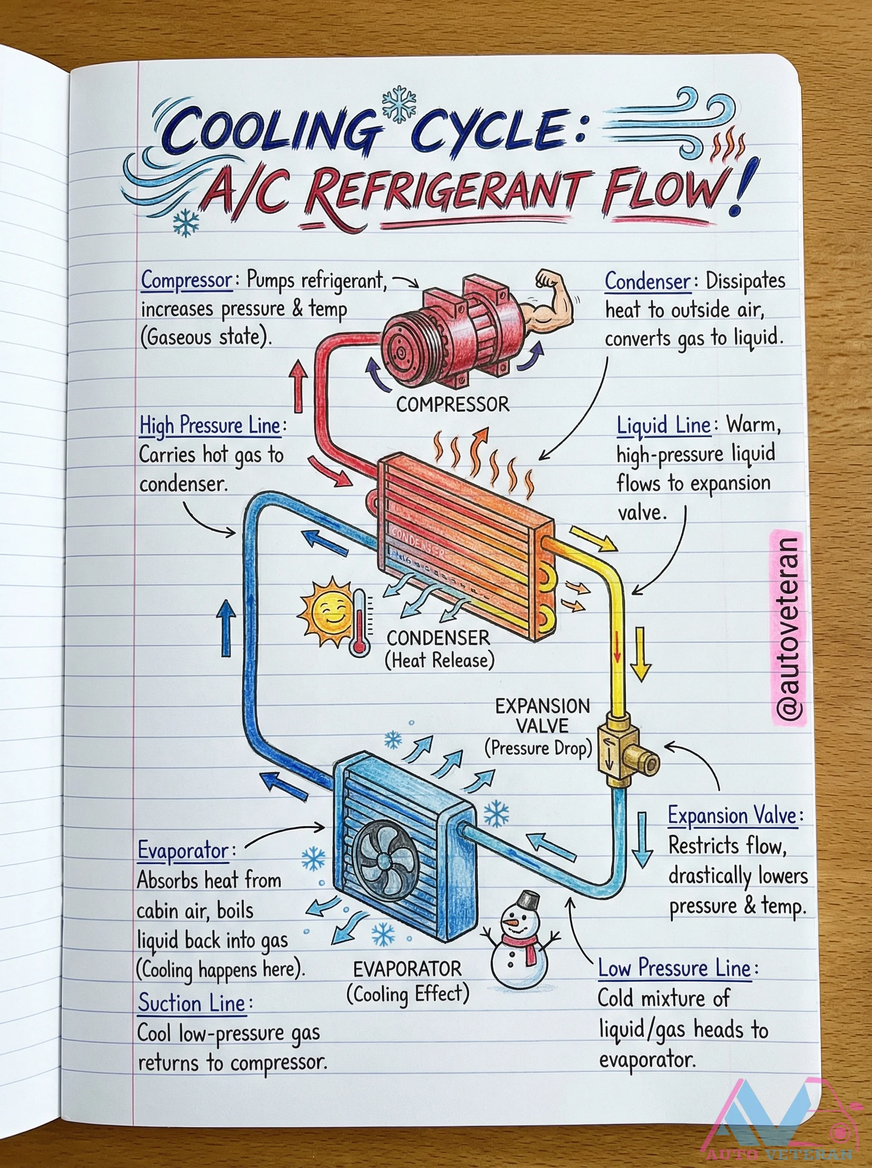
AC Refrigerant Flow in the Cooling Cycle
The automotive air conditioning system operates through a precise refrigerant flow cycle; starting at the compressor where refrigerant pressure increases, moving through the condenser to dissipate heat and convert gas to liquid, then passing through the expansion valve for pressure drop before entering the evaporator to absorb cabin heat and create cooling, with low pressure gas returning to complete the cycle.
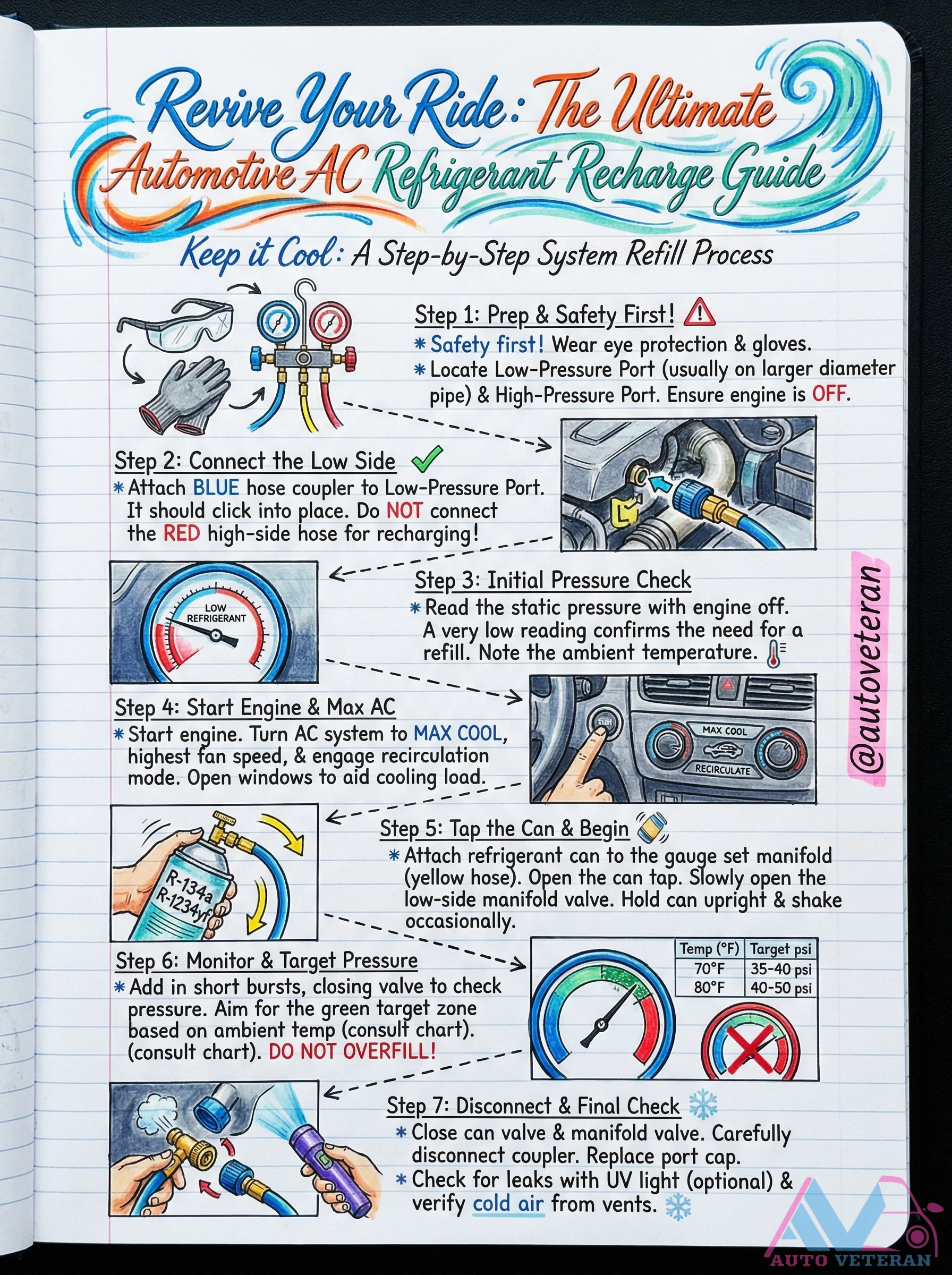
AC System Refill Step-by-Step Process Guide
This comprehensive guide details the precise procedure for recharging your vehicle's air conditioning system with R-134a refrigerant. The process begins with essential safety precautions, including wearing eye protection and gloves, and identifying the low-pressure port on the larger diameter pipe while ensuring the engine is off. You'll learn to connect the blue hose coupler properly, perform an initial static pressure check to confirm refill necessity, and note ambient temperature for accurate targeting. The guide then walks through starting the engine with AC set to MAX COOL at highest fan speed, attaching the refrigerant can to the manifold, and adding refrigerant in controlled bursts while monitoring pressure against a temperature-based chart. Critical warnings emphasize never connecting the red high-side port during recharge and avoiding overfilling. The final steps cover proper disconnection, leak checking with UV light, and verifying cold air output from vents.
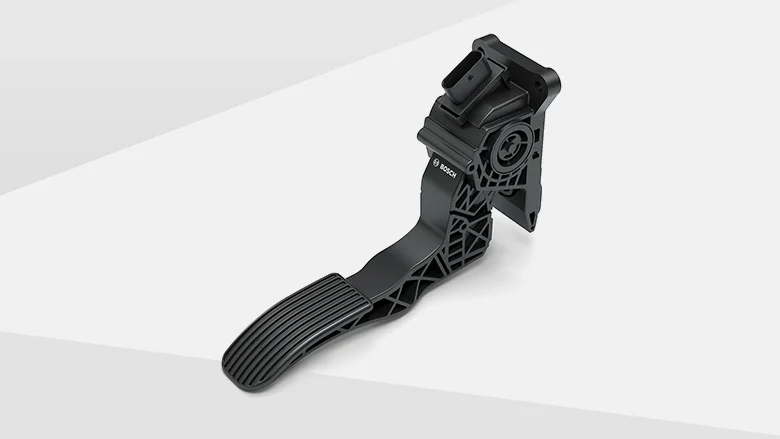
Accelerator (Gas Pedal)
The foot-operated pedal that controls the engine's throttle, regulating the amount of fuel and air mixture entering the engine. Pressing the accelerator increases engine speed and power output, making the vehicle move faster. In electronic throttle systems, the pedal sends signals to the engine control unit rather than operating a mechanical linkage.
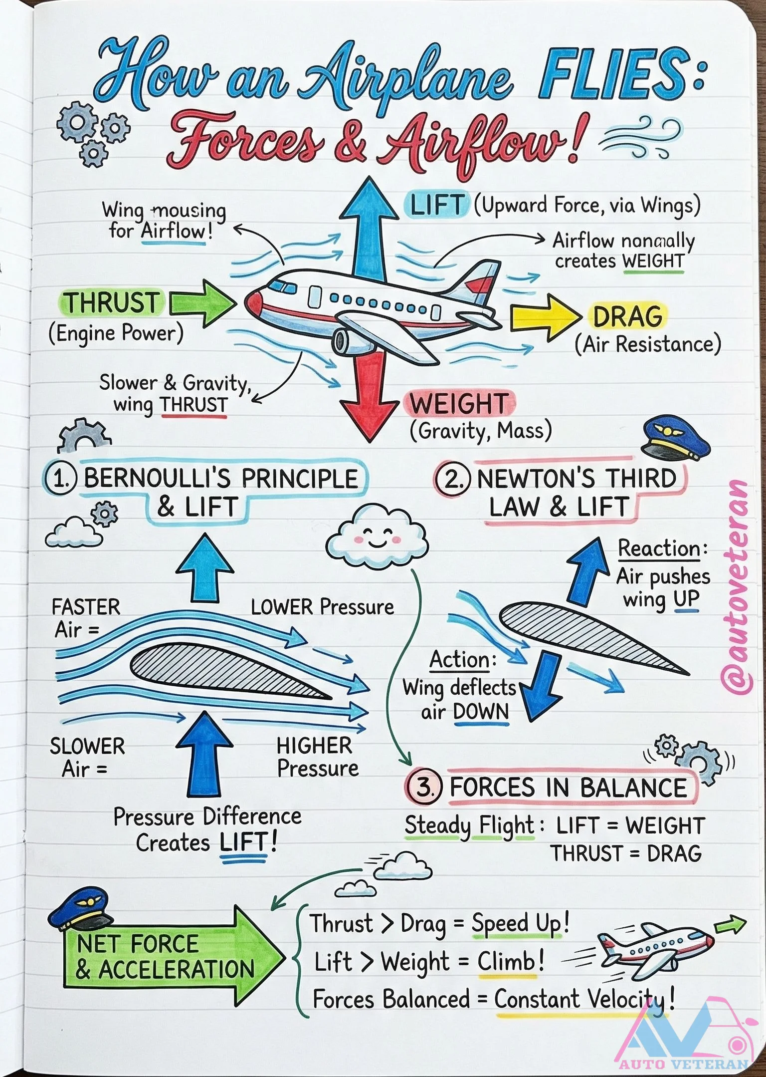
Aerodynamic Forces and Bernoulli's Principle in Flight
The fundamental physics of flight relies on the precise balance of four key forces: lift generated by wings counteracts weight from gravity, while thrust from engines overcomes drag from air resistance. Bernoulli's principle explains how faster airflow over a wing's curved upper surface creates lower pressure, producing upward lift. Simultaneously, Newton's third law contributes as wings deflect air downward, creating an equal and opposite reaction that further enhances lift. During steady flight, these forces achieve equilibrium with lift matching weight and thrust equaling drag, allowing for constant velocity. When thrust increases beyond drag, the resulting net force accelerates the aircraft, enabling climbs and maneuvers.
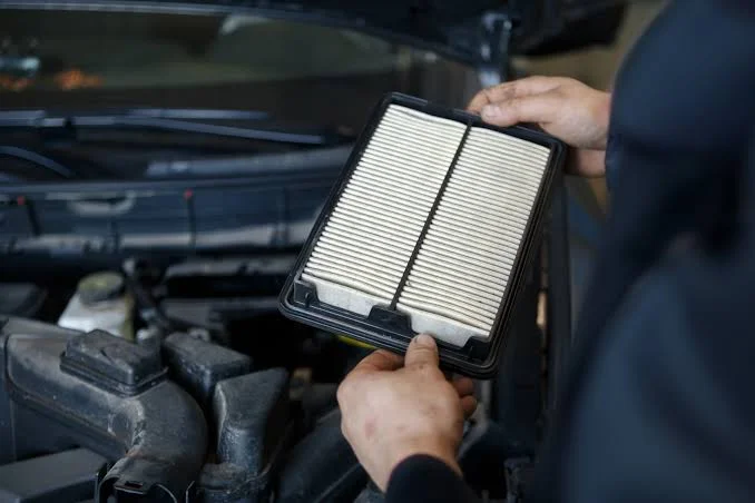
Air Filter
Located in the engine intake system, the air filter cleans the air before it enters the engine for combustion. It traps dust, dirt, and debris to protect the engine's internal parts. A clean air filter ensures better fuel efficiency, improved engine performance, and reduced harmful emissions.