Interactive Explorer
Air Intake Manifold Failure Symptoms and Service Notes
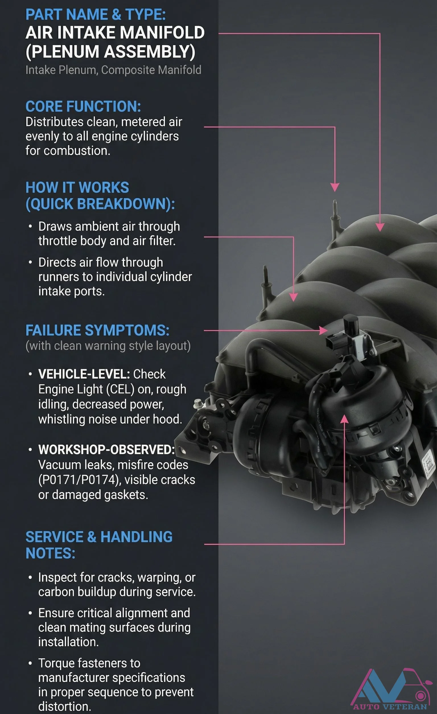
The composite plenum assembly distributes clean, metered air evenly to all engine cylinders for combustion. When this critical component fails, vehicle level symptoms include a check engine light illumination, rough idle with decreased power, and whistling noises under the hood. Workshop diagnostics reveal vacuum leaks, misfire codes like P0171 and P0174, and visible cracks or damaged gaskets. Proper service requires inspection for cracks, warping, and carbon buildup during maintenance. Critical alignment and clean surfaces are essential during installation, with fasteners torqued to manufacturer specifications in the proper sequence to prevent distortion.
Air Intake System
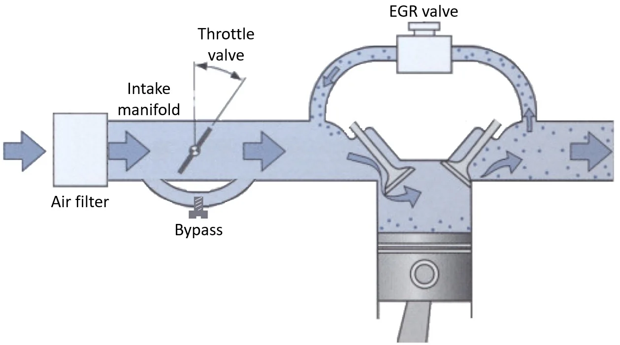
The network of components that delivers filtered air to the engine for combustion, including the air filter, intake manifold, throttle body, and connecting ducts. The system must provide adequate airflow while filtering contaminants. Performance modifications often focus on improving airflow through this system to increase engine power.
Airbag SRS Failure Symptoms and Inspection Tips
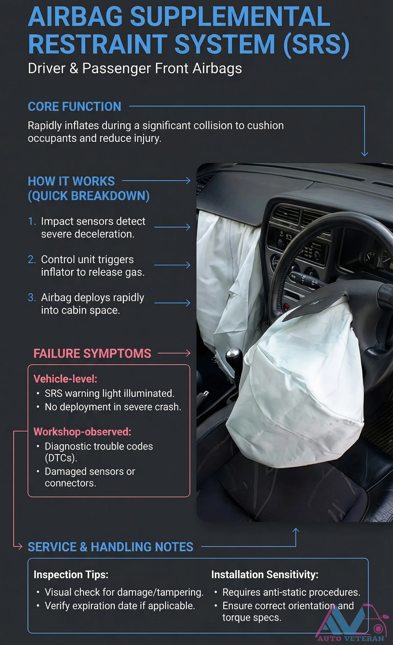
When the Supplemental Restraint System malfunctions, the SRS warning light illuminates on your dashboard, signaling potential non deployment during a severe collision. Diagnostic trouble codes reveal issues with damaged sensors or connectors, while proper inspection requires visual checks for tampering, adherence to anti static procedures, verification of expiration dates, and correct orientation with specified torque settings.
Airbag SRS Warning Light Fault Causes and Consequences
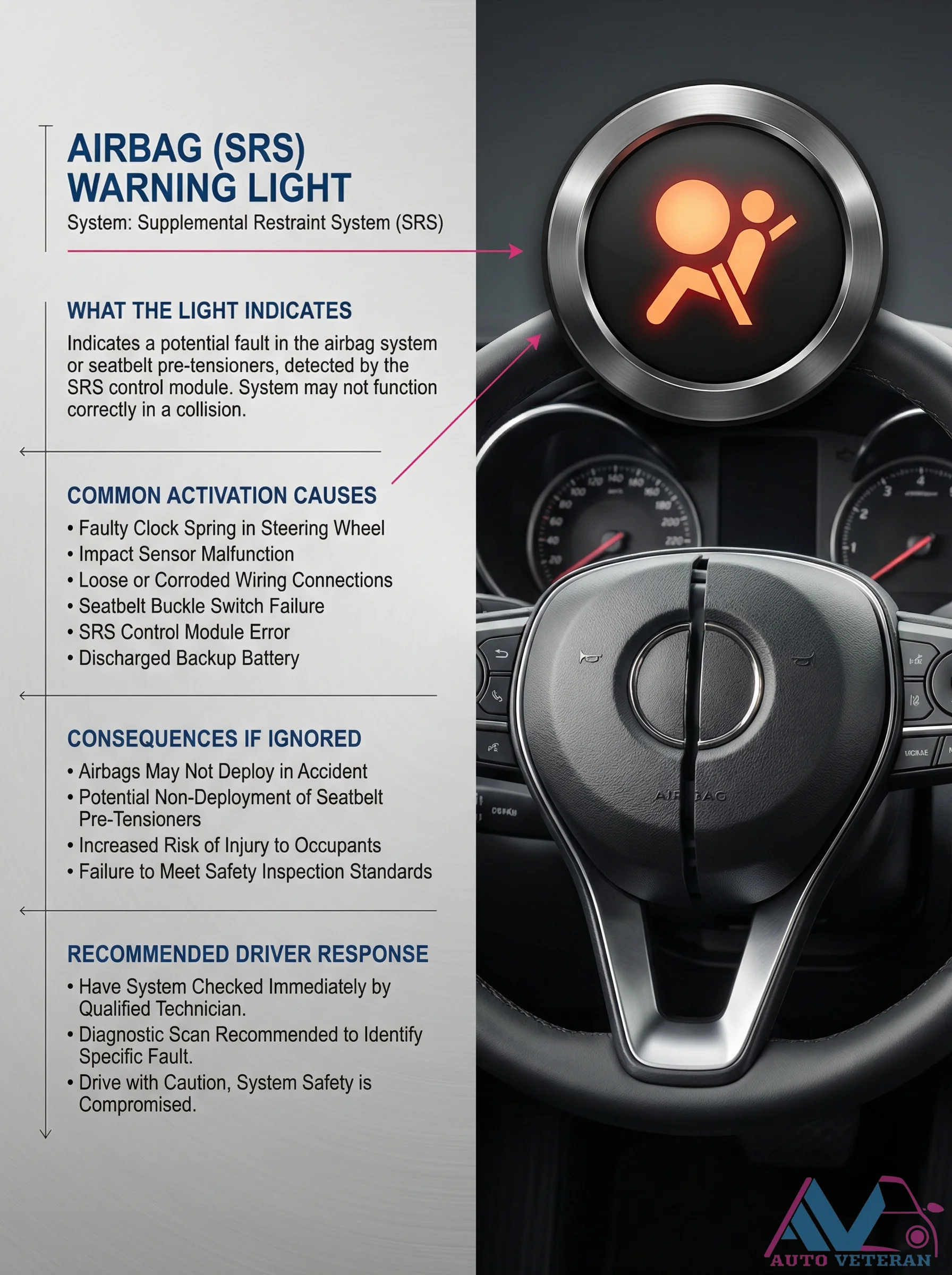
When the Supplemental Restraint System warning light illuminates on your dashboard, it signals a potential fault detected by the SRS control module that could prevent proper deployment of airbags or seatbelt pre tensioners during a collision. Common activation causes include a faulty clock spring in the steering wheel, impact sensor malfunctions, loose or corroded wiring connections, seatbelt buckle switch failures, SRS control module errors, or a discharged backup battery. Ignoring this warning increases occupant risk, may cause failure to meet safety inspection standards, and requires immediate diagnostic scanning by a qualified technician to identify the specific fault while driving with caution.
Airbag SRS Warning Light Symptoms and Causes
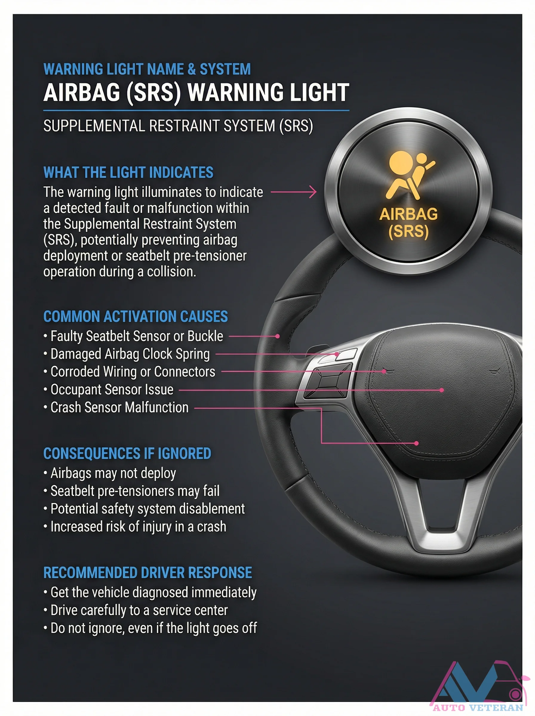
When your vehicle's Supplemental Restraint System warning light illuminates, it signals a detected fault that could prevent airbag deployment or seatbelt pre tensioner operation during a collision. Common activation causes include a faulty seatbelt sensor or buckle, damaged airbag clock spring, corroded wiring or connectors, occupant sensor issues, or crash sensor malfunction. Ignoring this warning can lead to airbags not deploying, seatbelt pre tensioners failing, potential safety system disablement, and increased injury risk in a crash. The recommended driver response is to get the vehicle diagnosed immediately and drive carefully to a service center, even if the light goes off.

Airbag System
A passive safety system consisting of inflatable cushions designed to protect occupants during collisions. Modern vehicles typically have multiple airbags including front, side, curtain, and knee airbags. The system uses crash sensors to detect impacts and rapidly inflate the bags using a chemical reaction, then quickly deflate to cushion occupants and reduce injury.
Aircraft Flight Forces and Principles of Soaring
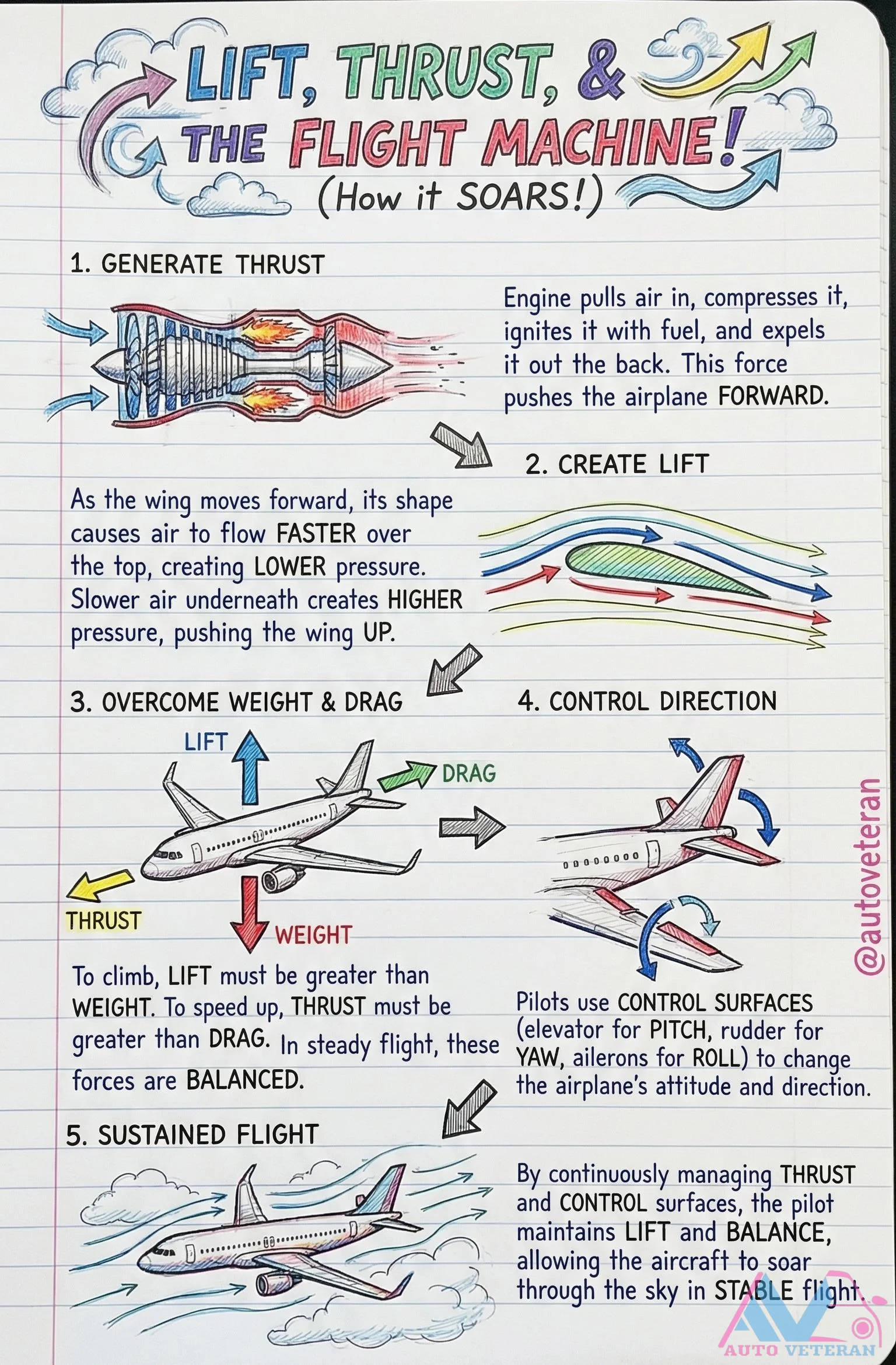
Understanding the four fundamental forces of flight is essential for aviation mechanics and enthusiasts. Thrust is generated when an engine compresses incoming air, mixes it with fuel, ignites the mixture, and expels it rearward to propel the aircraft forward. Lift occurs as the wing's shape causes air to flow faster over the top surface, creating lower pressure above and higher pressure below, pushing the wing upward. In steady flight, lift must balance weight, and thrust must overcome drag. Pilots use control surfaces like elevators for pitch, rudders for yaw, and ailerons for roll to adjust the aircraft's attitude and direction. Sustained flight requires continuous thrust management and control surface adjustments to maintain lift and balance, enabling stable soaring through the sky.
Aircraft Flight Mechanics and Principles
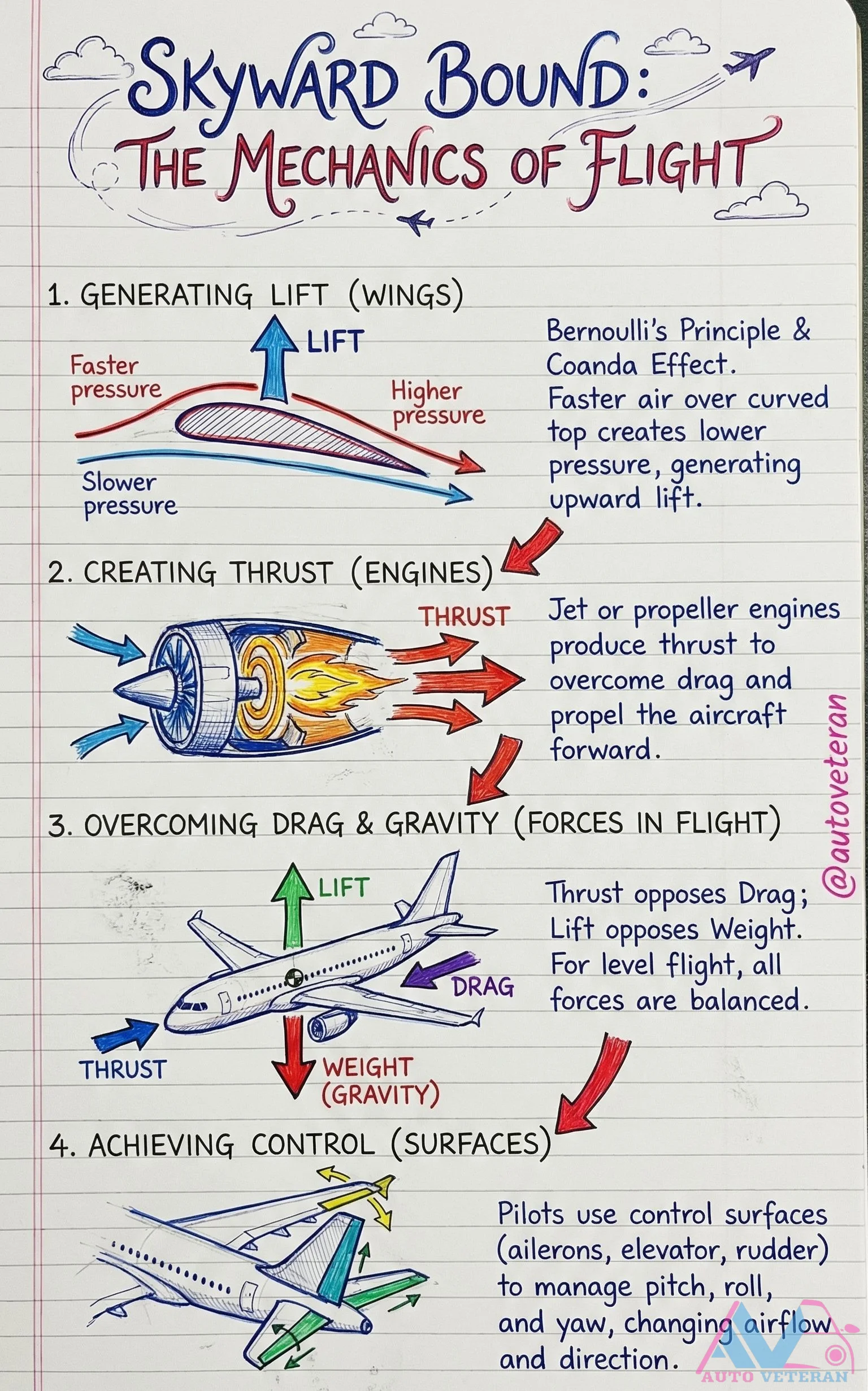
Understanding the fundamental mechanics of flight involves four key principles: generating lift through wings using Bernoulli's Principle and the Coanda Effect, where faster airflow over curved surfaces creates lower pressure and upward force; creating thrust with jet or propeller engines to overcome drag and propel forward; balancing forces in flight where lift opposes weight and thrust opposes drag for level flight; and achieving control through surfaces like ailerons, elevator, and rudder to manage pitch, roll, and yaw by changing airflow and direction.
Aircraft Lift Dynamics with Bernoulli and Coanda Effects
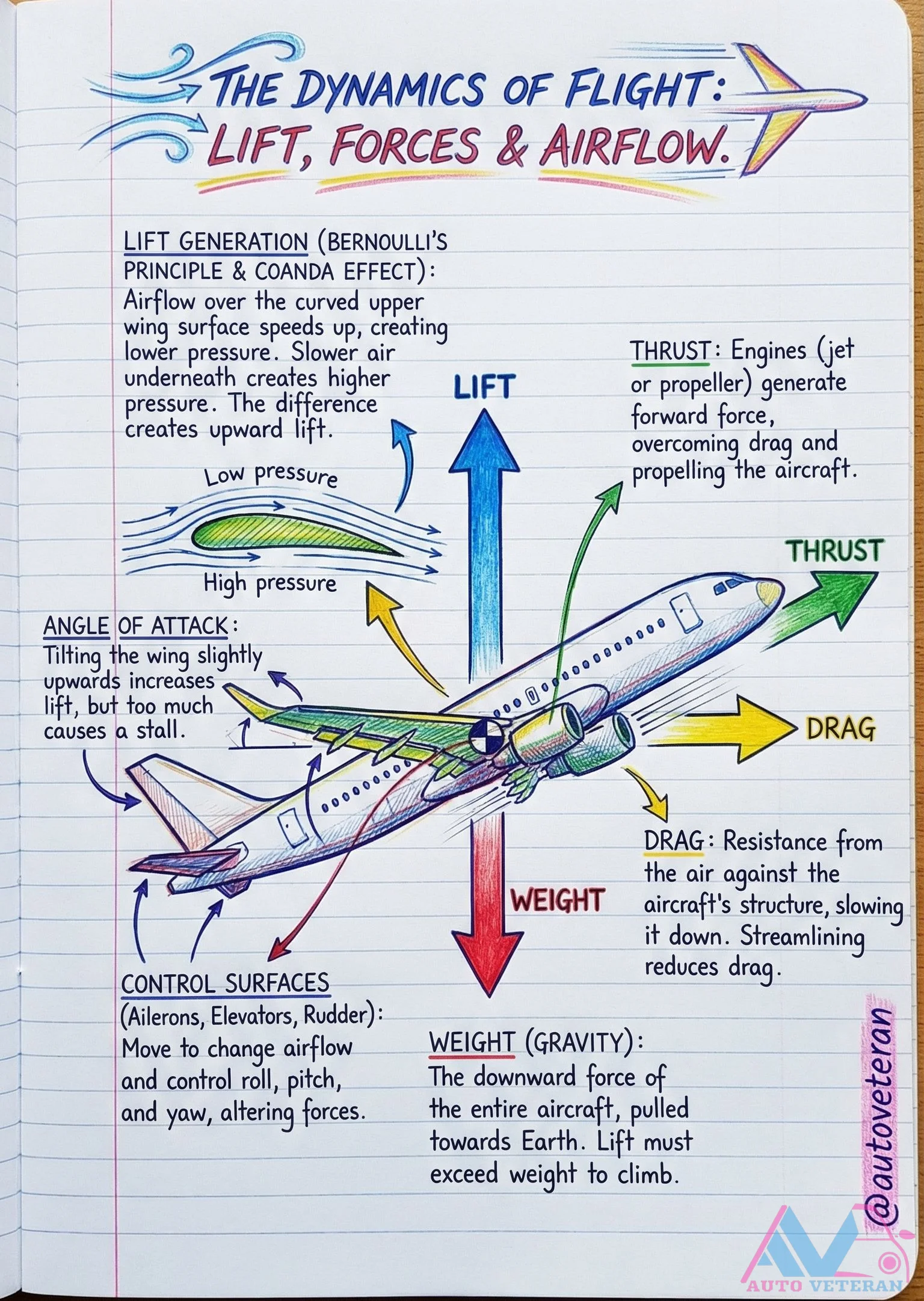
Understanding how aircraft generate lift involves two key aerodynamic principles working together. Bernoulli's principle explains how faster airflow over the curved upper wing surface creates lower pressure compared to the slower air underneath, producing upward force. The Coanda effect describes how airflow follows the wing's contour, enhancing this pressure differential. Tilting the wing at an angle of attack increases lift by altering airflow patterns, though excessive angles lead to aerodynamic stall where lift suddenly decreases. These forces must overcome the aircraft's weight for climbing, while thrust from engines counteracts drag resistance. Control surfaces like ailerons, elevators, and rudders manipulate airflow to manage roll, pitch, and yaw during flight.
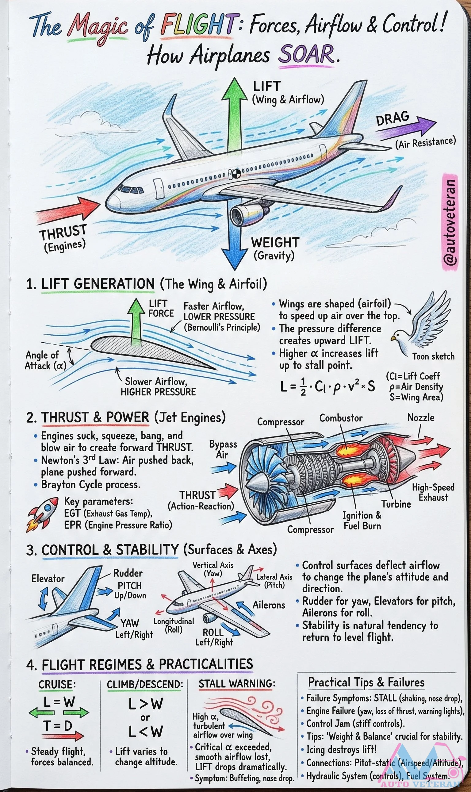
Airplane Flight Forces and Control Systems Explained
Understanding the fundamental forces and control systems that enable airplanes to fly is essential for aviation enthusiasts and pilots alike. The principles of lift generation through airfoil design and Bernoulli's principle create the upward force needed for flight, while thrust from jet engines using the Brayton cycle provides forward momentum. Control surfaces like elevators, rudders, and ailerons manipulate airflow to manage pitch, yaw, and roll, ensuring stable flight. Practical considerations include monitoring key parameters such as EGT and EPR, recognizing stall symptoms like buffeting and nose drop, and maintaining proper weight balance for optimal stability during all flight regimes from climb to cruise.
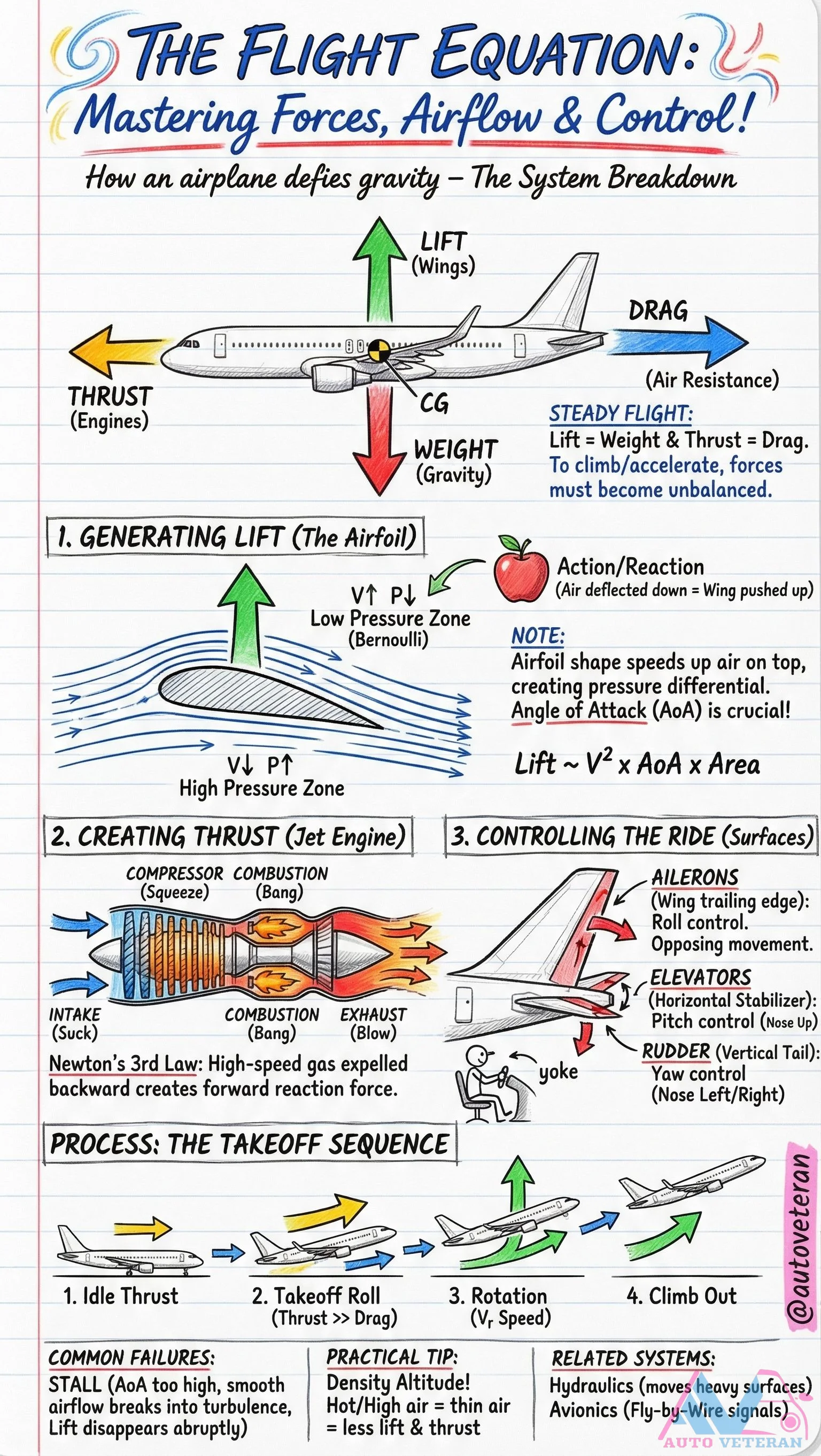
Airplane Flight Forces System Breakdown
Understanding how airplanes defy gravity requires mastering the four fundamental forces of flight: lift generated by wings through airfoil design and angle of attack, thrust created by jet engines via Newton's third law, drag as air resistance, and weight from gravity. The system breakdown reveals how steady flight occurs when lift equals weight and thrust equals drag, while climbing or accelerating requires unbalanced forces. Key components include wings generating lift through pressure differentials, jet engines producing thrust via intake, compression, combustion, and exhaust, and control surfaces like ailerons for roll, elevators for pitch, and rudder for yaw. The takeoff sequence progresses from idle thrust through rotation to climb out, with critical attention to angle of attack to prevent stalls where airflow breaks into turbulence and lift disappears abruptly.

Alignment (Wheel Alignment)
The adjustment of a vehicle's suspension system to ensure that all wheels are positioned correctly relative to each other and the road surface. Proper alignment involves setting the correct angles for camber (wheel tilt), caster (steering axis angle), and toe (wheel direction). Poor alignment causes uneven tire wear, steering problems, and reduced fuel economy.
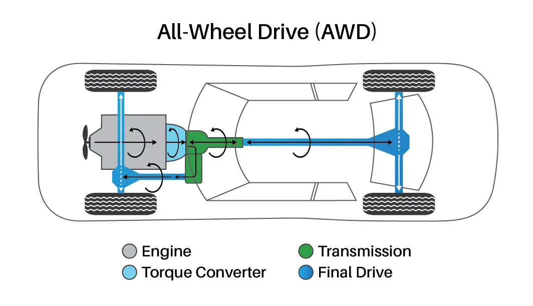
All-Wheel Drive (AWD)
A drivetrain system that automatically distributes engine power to all four wheels as needed, providing improved traction and handling in various road conditions. Unlike 4WD systems, AWD operates continuously without driver input and typically uses a center differential to allow for speed differences between front and rear wheels during normal driving.
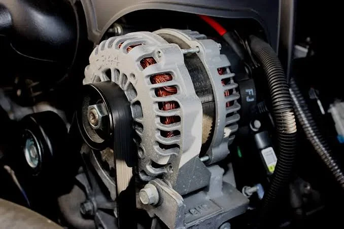
Alternator
The alternator is responsible for generating electricity while the engine runs. It keeps the battery charged and powers essential systems like the lights, dashboard, and infotainment. Without a properly functioning alternator, a vehicle’s battery would quickly lose charge, causing electrical systems to fail.
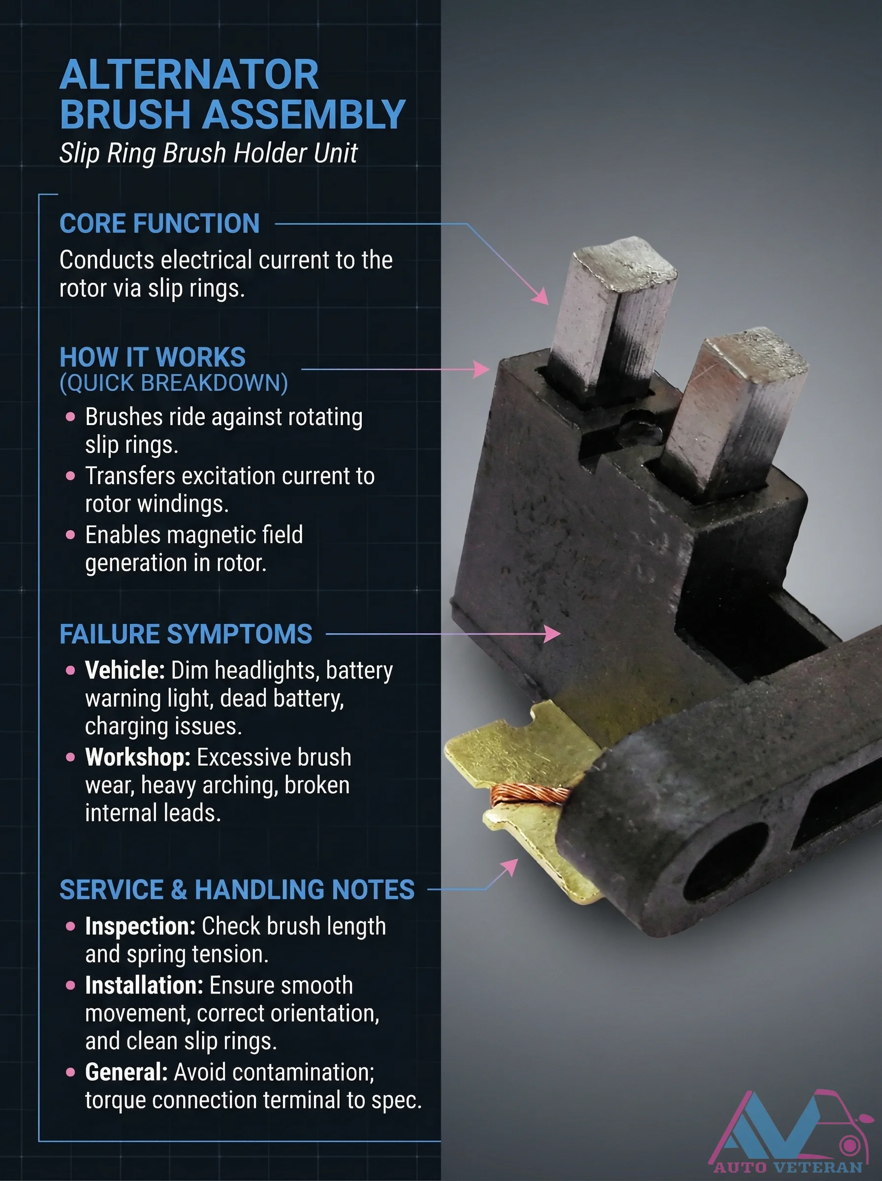
Alternator Brush Assembly Failure Symptoms and Inspection
The alternator brush assembly conducts electrical current to the rotor via slip rings, enabling magnetic field generation. When brushes wear excessively or develop issues like arching or broken leads, symptoms include dim headlights, battery warning lights, dead batteries, and charging problems. Proper inspection involves checking brush length and spring tension, while installation requires ensuring smooth movement, correct orientation, and clean slip rings to avoid contamination and maintain proper torque specifications.
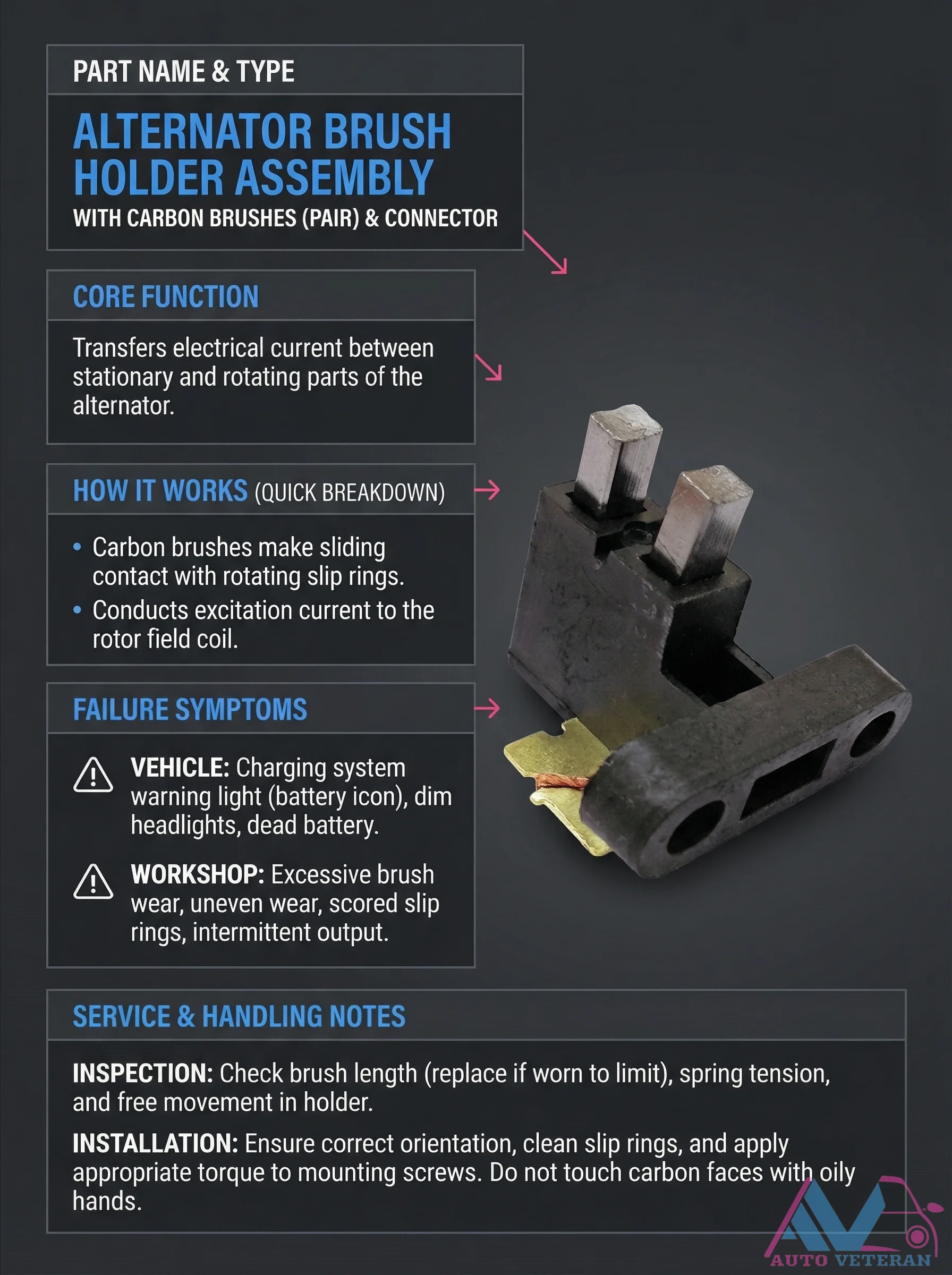
Alternator Brush Holder Assembly Failure Symptoms
When the alternator brush holder assembly with carbon brushes wears down, your vehicle's charging system begins to falter. The carbon brushes make sliding contact with rotating slip rings to conduct excitation current to the rotor field coil. Failure symptoms include the charging system warning light illuminating, dim headlights, and a dead battery. In the workshop, technicians look for excessive or uneven brush wear, scored slip rings, and intermittent electrical output. Proper inspection involves checking brush length against wear limits, verifying spring tension, and ensuring free movement in the holder. During installation, correct orientation is crucial, slip rings must be cleaned, mounting screws torqued appropriately, and carbon faces should never be touched with oily hands to maintain conductivity.
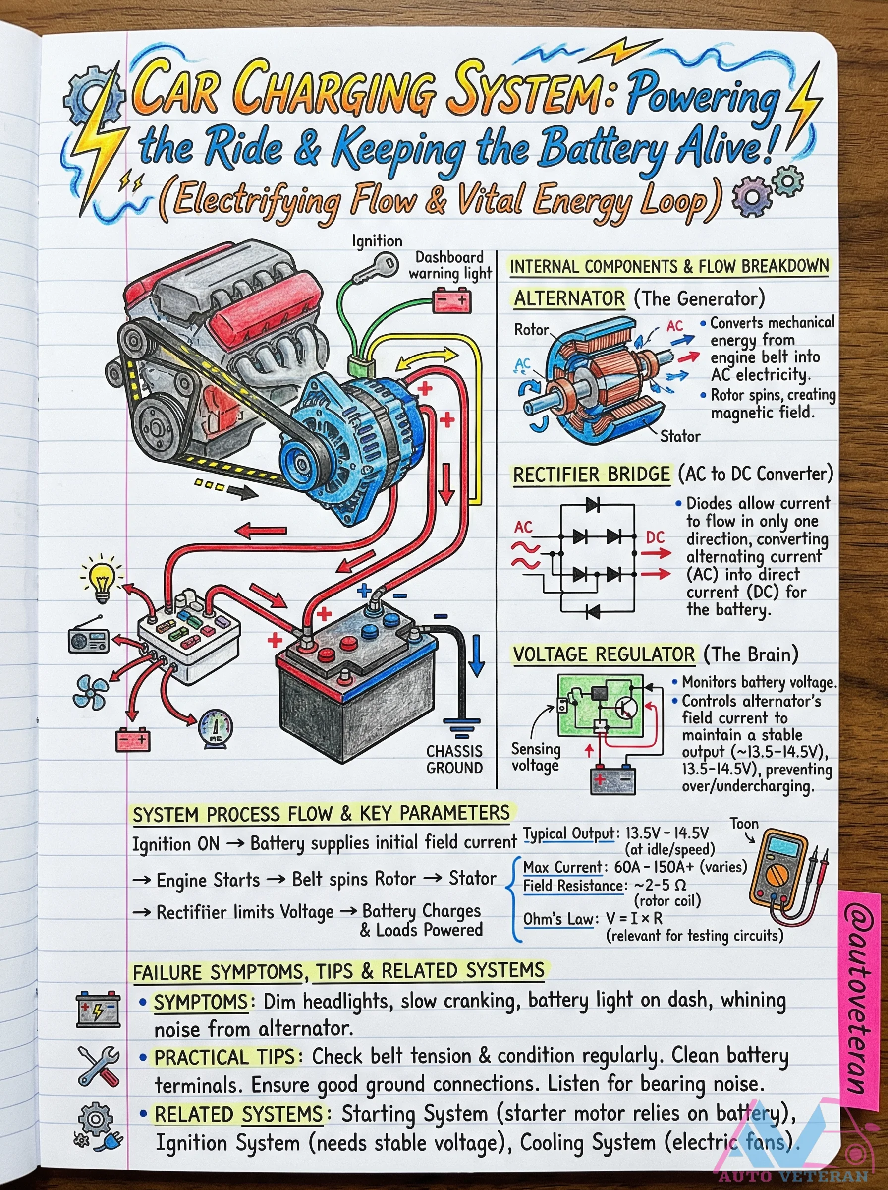
Alternator Charging System Internal Components and Flow
The automotive charging system converts mechanical energy into electrical power through a precise sequence. The alternator's rotor spins to generate AC electricity, which the rectifier bridge converts to DC using diodes that allow current flow in only one direction. A voltage regulator monitors battery output, maintaining a stable 13.5 to 14.5 volts by controlling field current, preventing overcharging or undercharging. Key parameters include typical output voltages at idle and higher speeds, maximum current ranging from 60 to over 150 amps, and rotor coil field resistance of 2 to 5 ohms. System failure symptoms include dim headlights, slow engine cranking, dashboard warning lights, and unusual alternator noises. Regular maintenance involves checking belt tension, cleaning terminals, ensuring solid connections, and listening for bearing wear.
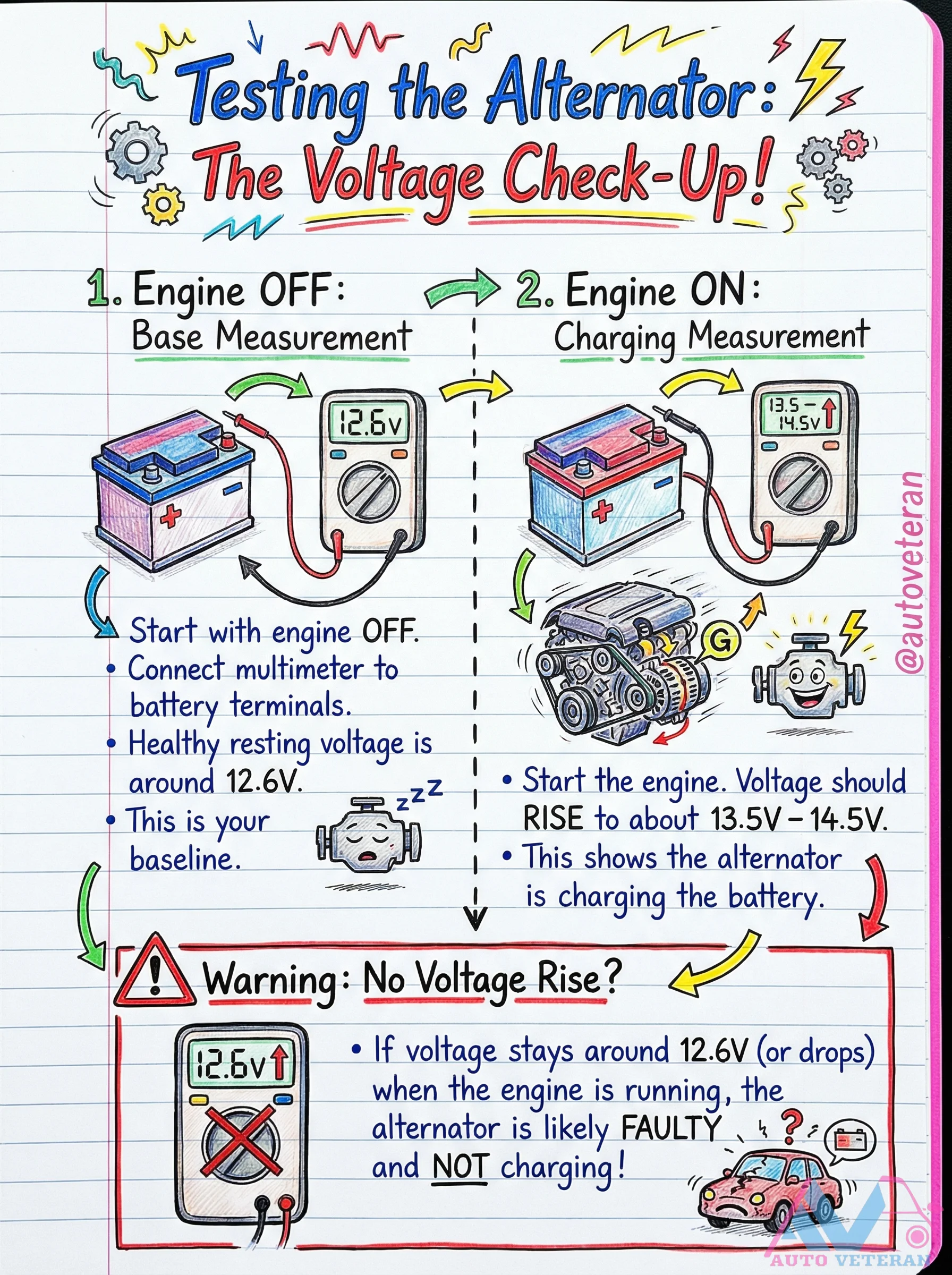
Alternator Charging Test Procedure with Voltage Measurements
To determine if your alternator is functioning properly, begin with the engine off and measure the battery voltage at the terminals, which should read approximately 12.6 volts as a baseline. Start the engine and observe the voltage reading; a healthy alternator will increase this to between 13.5 and 14.5 volts, indicating it is charging the battery effectively. If the voltage remains around 12.6 volts or drops while the engine runs, this signals a faulty alternator that is not charging, requiring immediate attention to prevent battery drain and electrical system failure.
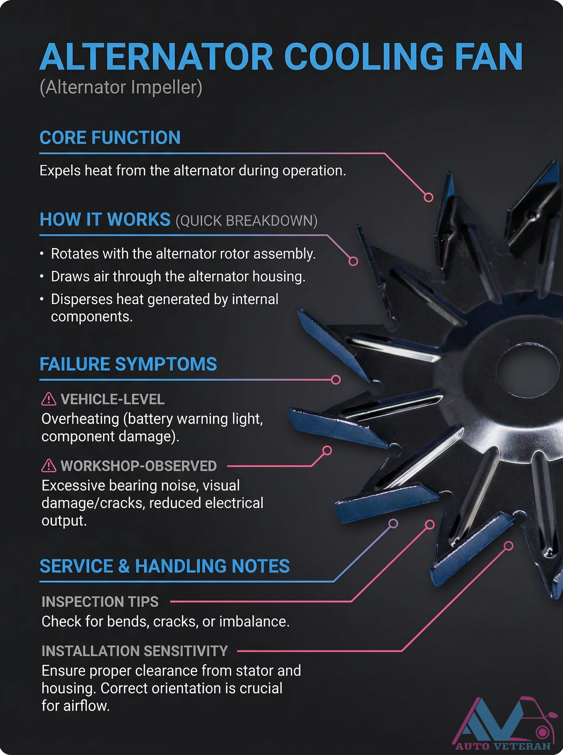
Alternator Cooling Fan Failure Symptoms and Inspection
The alternator cooling fan, also known as the alternator impeller, plays a critical role in expelling heat from the alternator during operation by rotating with the rotor assembly to draw air through the housing and disperse internal heat. When this component fails, vehicle level symptoms include overheating, often signaled by the battery warning light and potential component damage. In the workshop, technicians may observe excessive bearing noise, visual damage such as cracks, and reduced electrical output. Proper inspection involves checking for bends, cracks, or imbalance, while installation requires ensuring proper clearance from the stator and housing with correct orientation for optimal airflow.
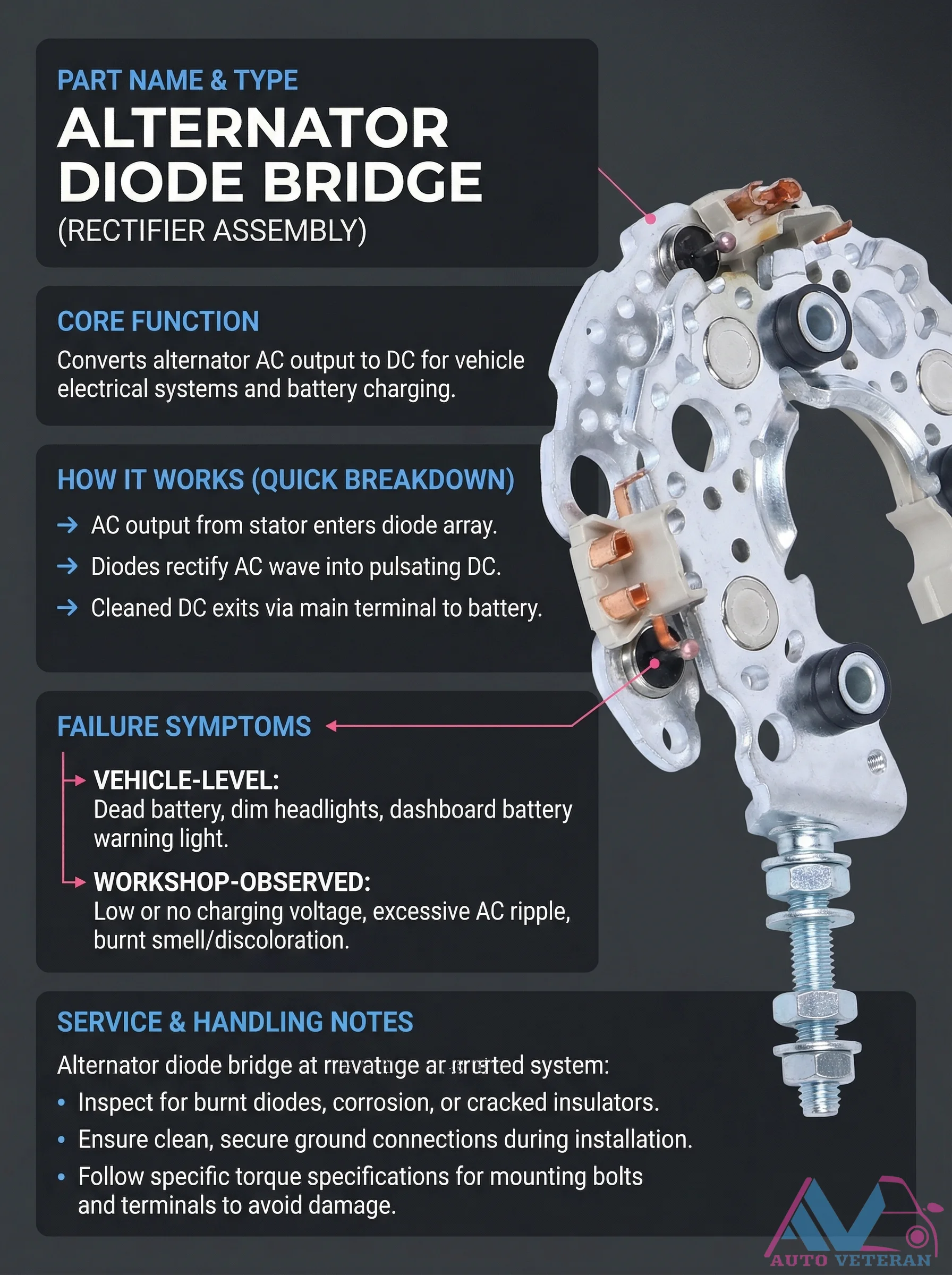
Alternator Diode Bridge Failure Symptoms and Service
The alternator diode bridge, also known as the rectifier assembly, serves the critical function of converting AC output from the stator into DC power for vehicle electrical systems and battery charging. When this component fails, vehicle level symptoms include a dead battery, dim headlights, and the dashboard battery warning light illuminating. In the workshop, technicians observe low or no charging voltage, excessive AC ripple, and physical signs like burnt smells or discoloration. Proper service involves inspecting for burnt diodes, corrosion, or cracked insulators, ensuring clean and secure ground connections, and following specific torque specifications for mounting bolts and terminals to prevent damage during installation.