Interactive Explorer
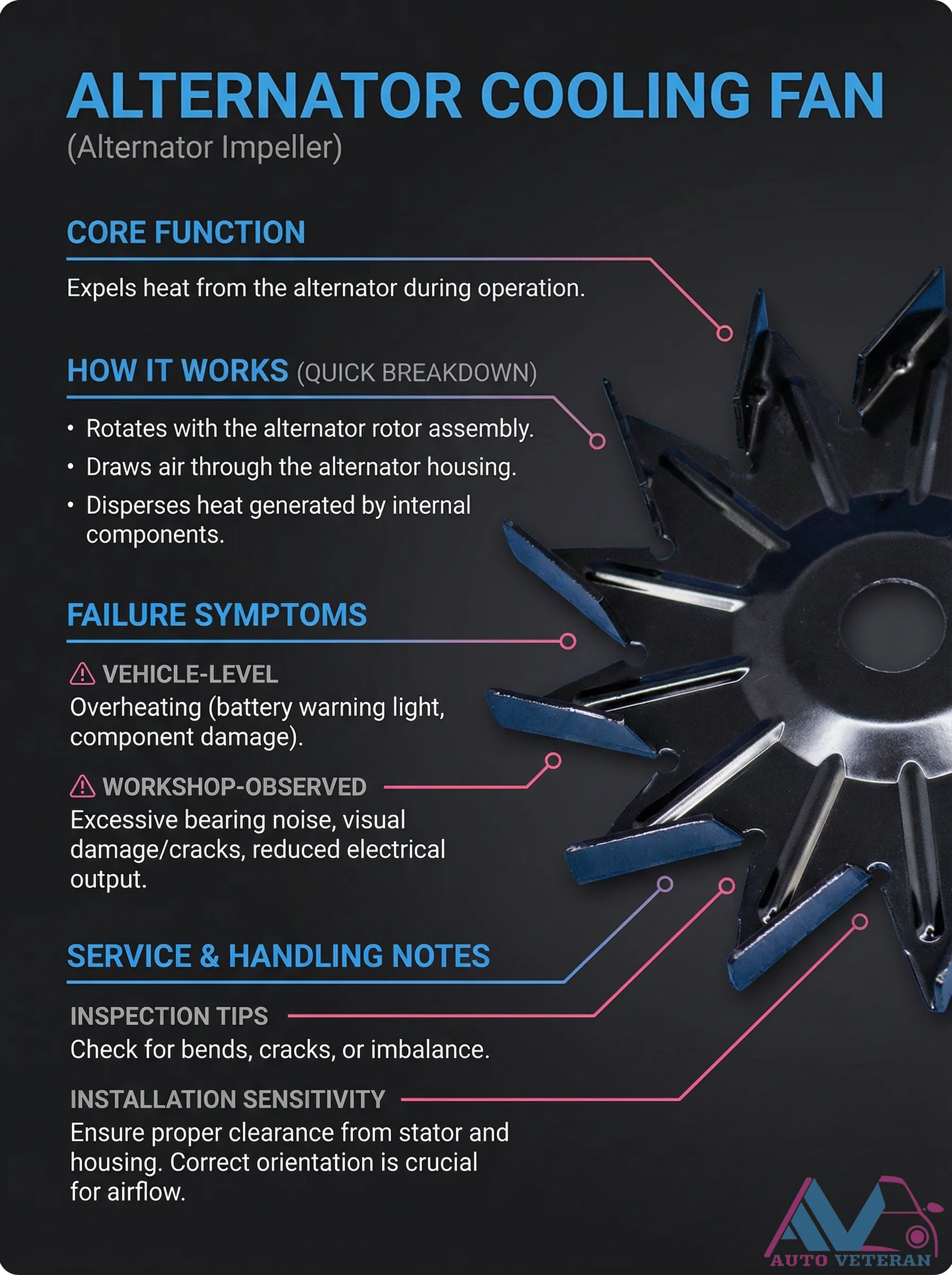
Alternator Cooling Fan Failure Symptoms and Inspection
The alternator cooling fan, also known as the alternator impeller, plays a critical role in expelling heat from the alternator during operation by rotating with the rotor assembly to draw air through the housing and disperse internal heat. When this component fails, vehicle level symptoms include overheating, often signaled by the battery warning light and potential component damage. In the workshop, technicians may observe excessive bearing noise, visual damage such as cracks, and reduced electrical output. Proper inspection involves checking for bends, cracks, or imbalance, while installation requires ensuring proper clearance from the stator and housing with correct orientation for optimal airflow.
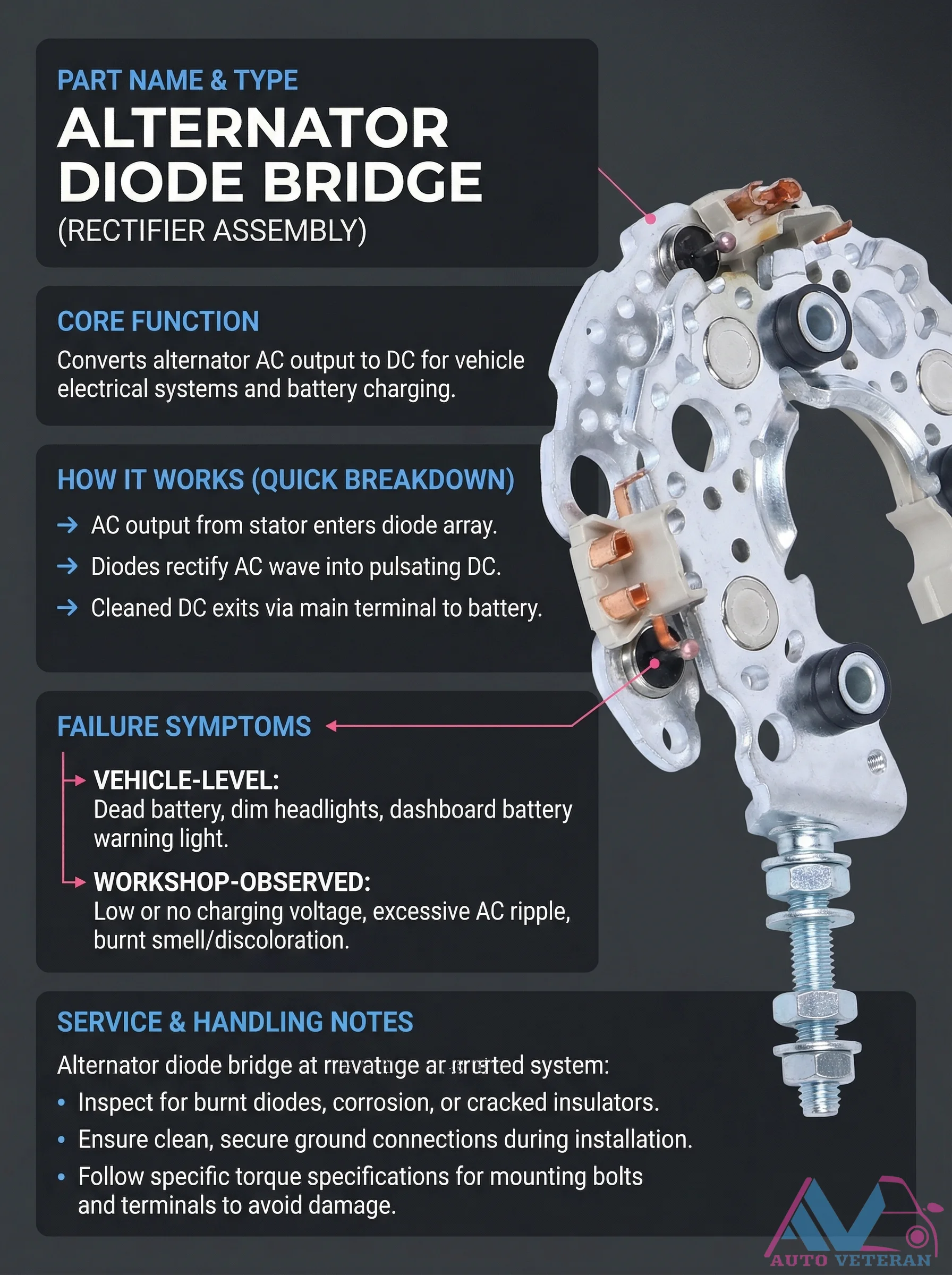
Alternator Diode Bridge Failure Symptoms and Service
The alternator diode bridge, also known as the rectifier assembly, serves the critical function of converting AC output from the stator into DC power for vehicle electrical systems and battery charging. When this component fails, vehicle level symptoms include a dead battery, dim headlights, and the dashboard battery warning light illuminating. In the workshop, technicians observe low or no charging voltage, excessive AC ripple, and physical signs like burnt smells or discoloration. Proper service involves inspecting for burnt diodes, corrosion, or cracked insulators, ensuring clean and secure ground connections, and following specific torque specifications for mounting bolts and terminals to prevent damage during installation.
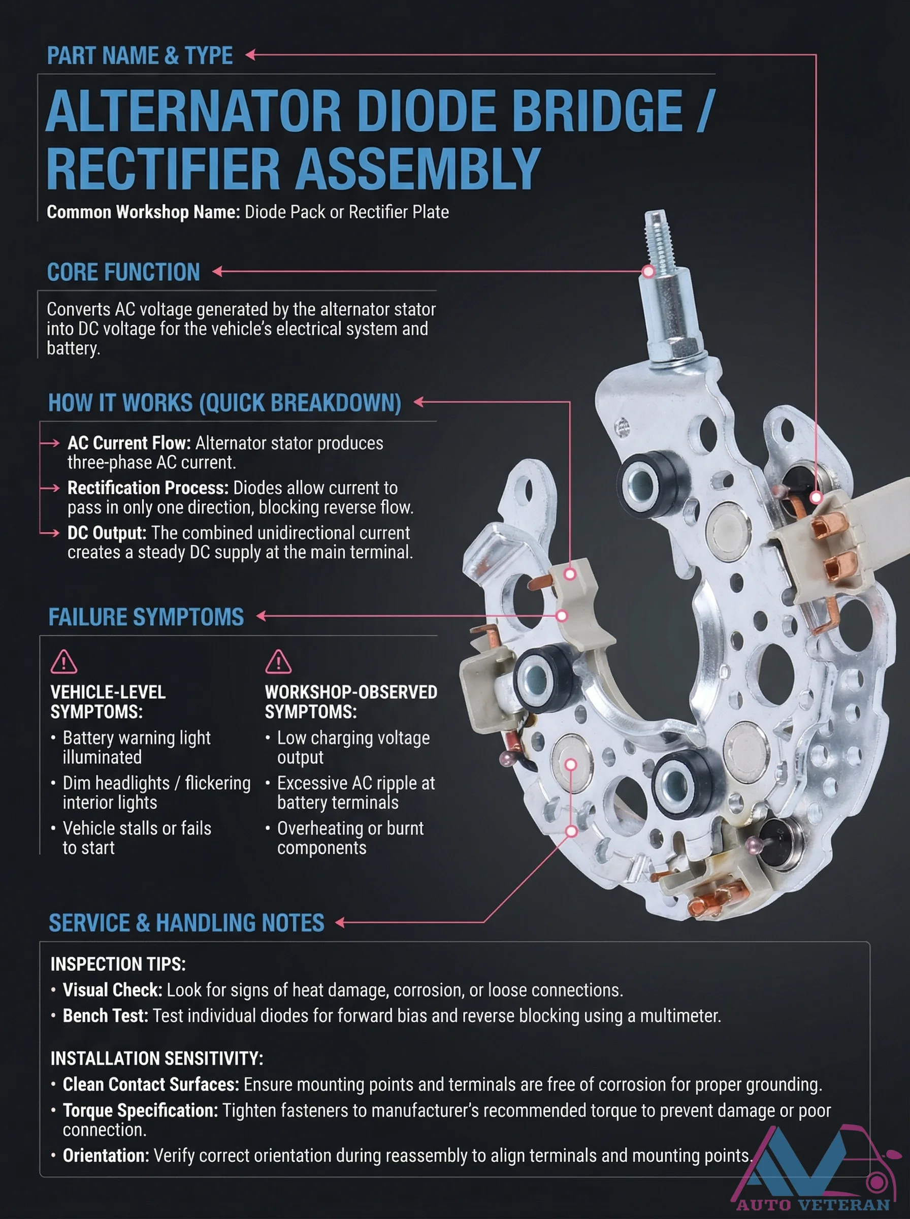
Alternator Diode Bridge Failure Symptoms and Testing
The alternator diode bridge, also known as a rectifier plate or diode pack, serves the critical function of converting three phase AC current from the stator into steady DC voltage for the vehicle's electrical system and battery charging. When this component fails, drivers experience symptoms like a battery warning light illuminating, dim or flickering headlights, vehicle stalling, or failure to start. Technicians can identify issues through visual inspection for heat damage or corrosion, and bench testing individual diodes with a multimeter to check forward bias and reverse blocking capabilities. Proper installation requires cleaning contact surfaces, applying correct torque specifications, and verifying orientation to ensure reliable operation.
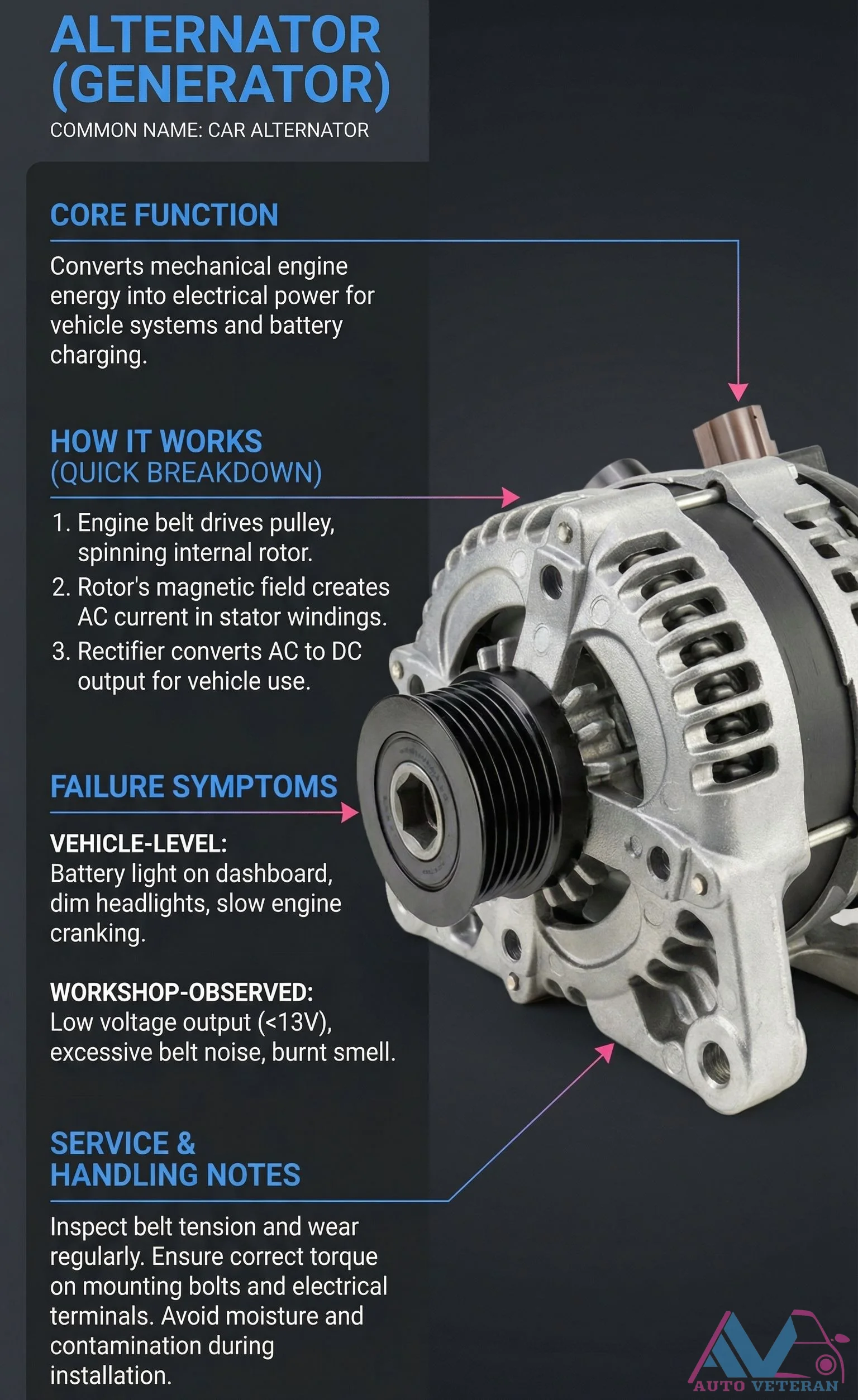
Alternator Failure Symptoms and Service Handling Notes
When your vehicle's alternator begins to fail, you'll notice clear symptoms like the battery light illuminating on the dashboard, dimming headlights, and slow engine cranking during startup. In the workshop, technicians observe low voltage output below 13 volts, excessive belt noise, and sometimes a burnt smell indicating electrical issues. Proper maintenance includes regularly inspecting belt tension and wear, ensuring correct torque on mounting bolts and electrical terminals, and avoiding moisture and contamination during installation to extend component life.
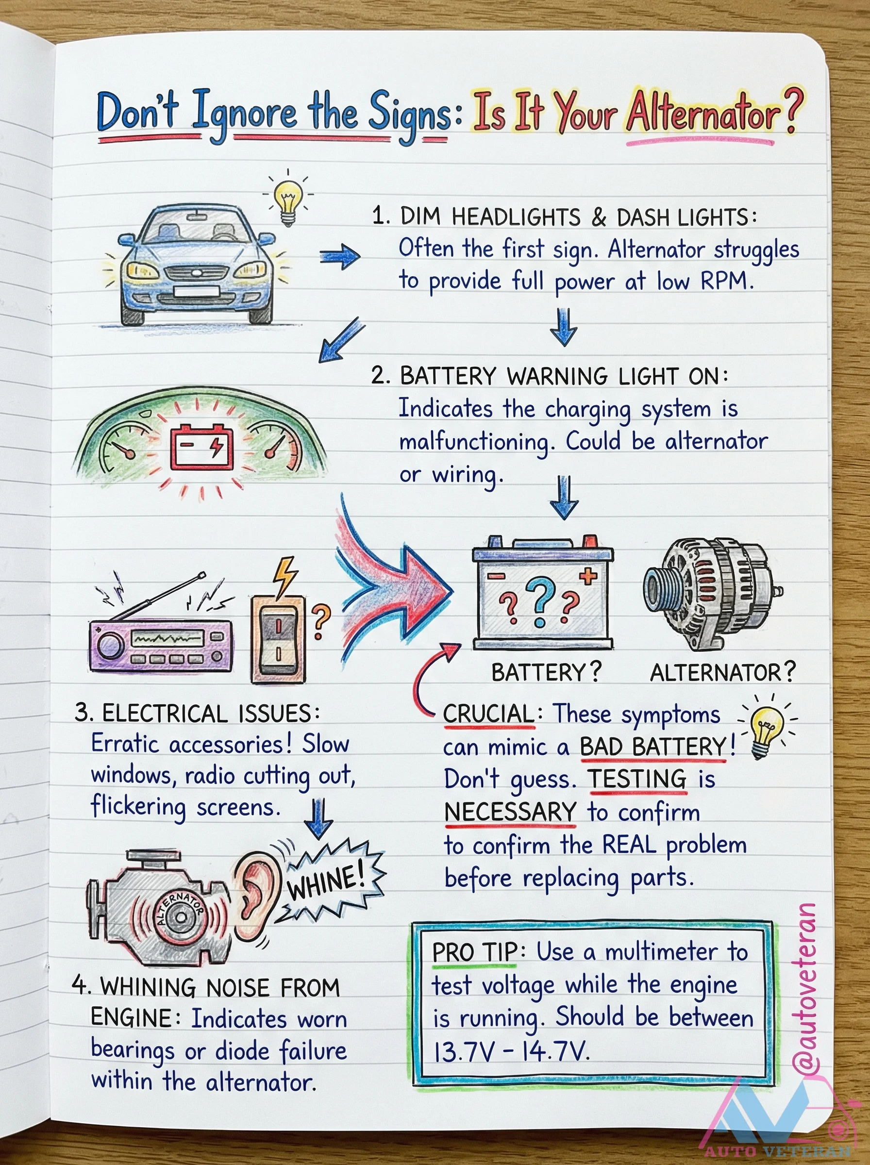
Alternator Failure Symptoms and Testing Guide
When your vehicle's alternator begins to fail, several distinct symptoms emerge that can help you diagnose the issue before it leaves you stranded. Dim headlights and dashboard lights often appear first, indicating the alternator struggles to provide full power at low RPM. The battery warning light illuminates when the charging system malfunctions, though this symptom can mimic a bad battery, making proper testing crucial. Electrical issues manifest as erratic accessories, slow power windows, radio failures, and flickering screens. A whining noise from the engine compartment typically indicates worn bearings or diode failure within the alternator assembly. Professional mechanics recommend using a multimeter to test the charging system while the engine is running, with proper voltage readings falling between 13.7 and 14.7 volts. Never guess between alternator and battery problems; accurate testing prevents unnecessary part replacement and ensures you address the real electrical system issue.
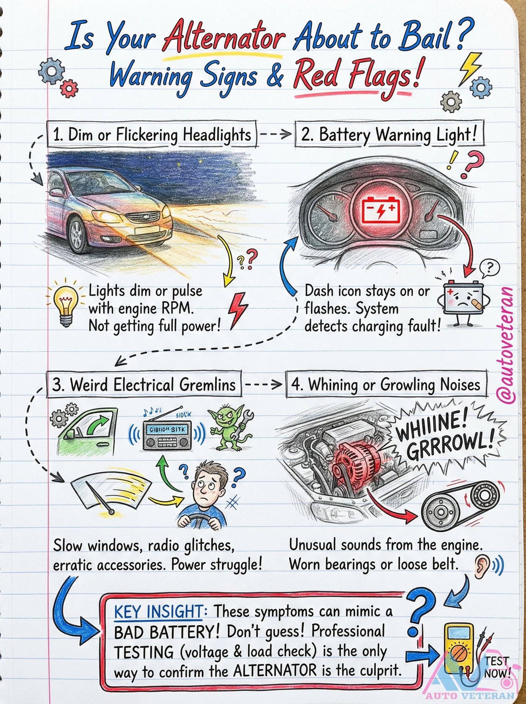
Alternator Failure Symptoms and Warning Signs
Recognizing alternator failure early can prevent roadside breakdowns; key symptoms include dim or flickering headlights that change with engine RPM, a battery warning light flashing on the dashboard, electrical gremlins like slow power windows and radio glitches, and unusual whining or growling noises from worn bearings or loose belts. These signs often mimic a bad battery, making professional voltage and load testing essential to confirm the alternator as the true culprit before complete failure occurs.
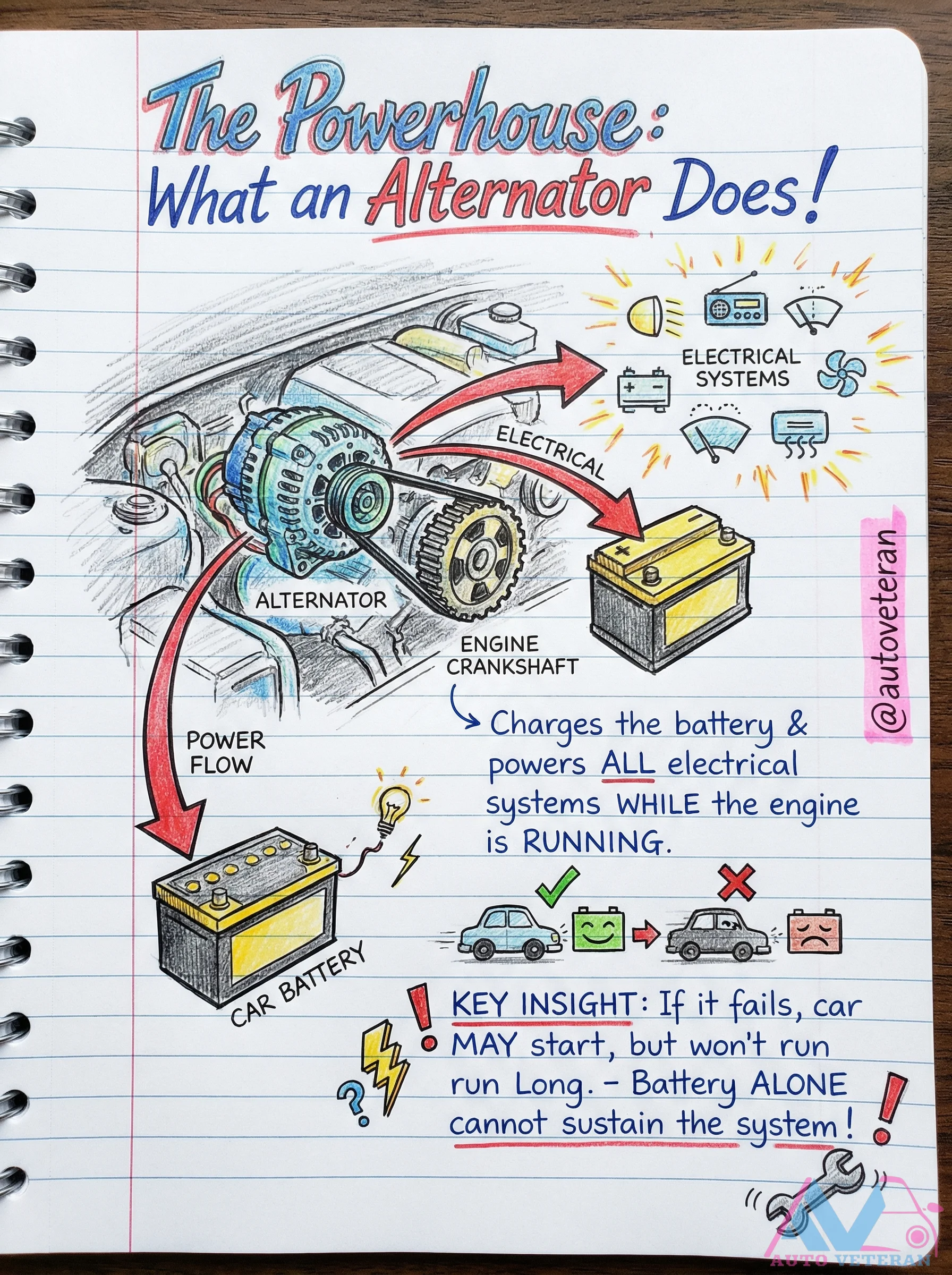
Alternator Function and Power Flow Diagram
The alternator serves as the heart of your vehicle's electrical system, generating power to charge the battery and supply all electrical components while the engine runs. A key insight reveals that if it fails, the car may start initially but cannot sustain operation alone, as the battery cannot power the entire electrical system indefinitely, leading to eventual shutdown.
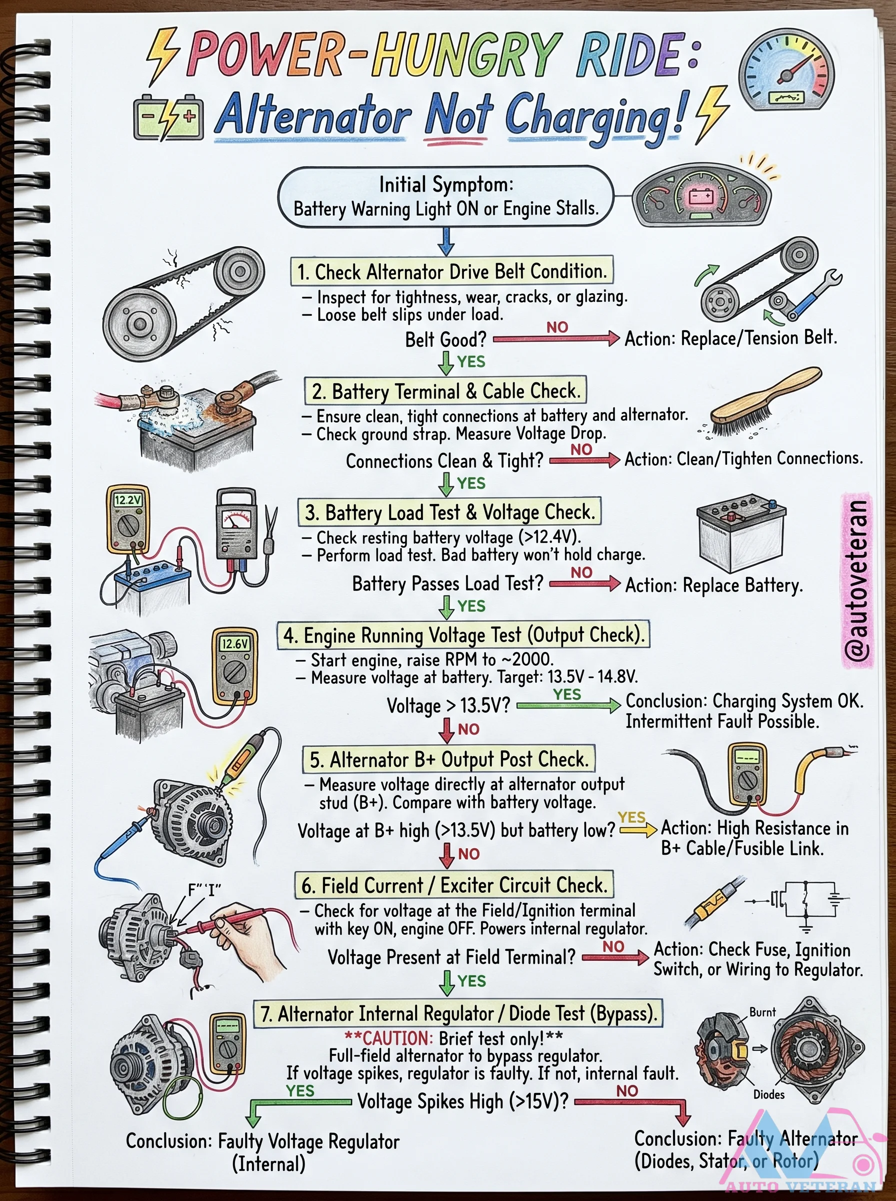
Alternator Not Charging Diagnostic Steps
When your alternator stops charging, the first sign is often a battery warning light or engine stalling. Start by checking the alternator drive belt for tightness, wear, or glazing; a loose belt slips under load. Inspect all terminal and cable connections at the battery and alternator, including the ground strap, and perform a voltage drop test. Measure resting battery voltage above 12.4V and perform a load test; a bad battery won't hold charge. With the engine running at 2000 RPM, test voltage at the battery targeting 13.5V to 14.8V. If voltage is low, check the B+ output post at the alternator: if high at the alternator but low at the battery, there is high resistance in the B+ cable or fusible link. For the field current exciter circuit, check for voltage at the field terminal with key on and engine off; if missing, inspect fuses, ignition switch, or wiring to the regulator. Finally, perform an internal regulator/diode test by briefly full fielding the alternator to bypass the regulator; voltage spikes over 15V indicate a faulty regulator, otherwise the alternator has internal faults in diodes, stator, or rotor.
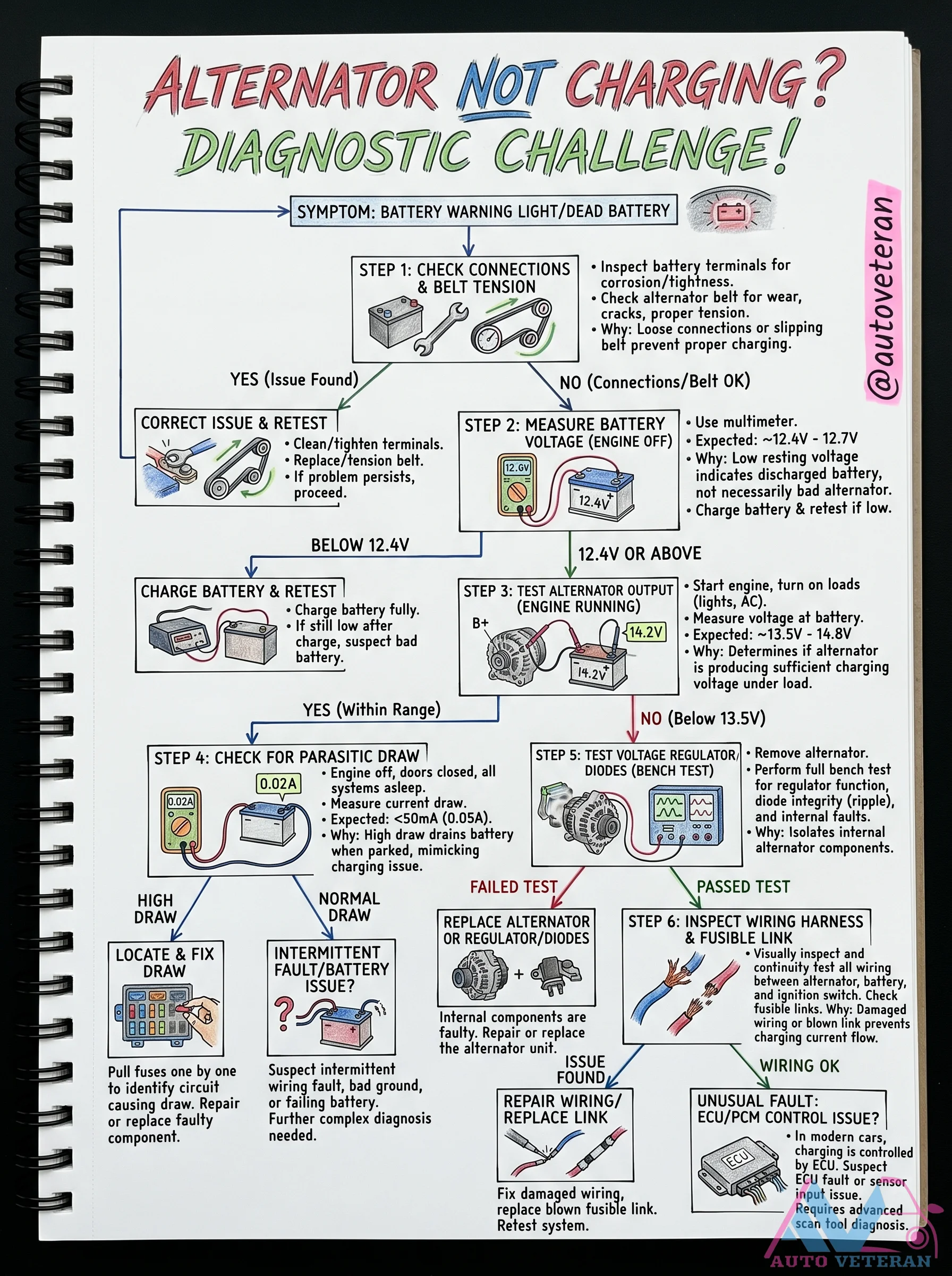
Alternator Not Charging: Diagnostic Steps
When your alternator fails to charge, the battery warning light illuminates and the battery dies. Start by checking battery terminal connections and belt tension; loose connections or slipping belts prevent proper charging. Measure battery voltage with the engine off: expect around 12.4V to 12.7V. Low resting voltage indicates a discharged battery, but not necessarily a bad alternator. Then test alternator output with the engine running and loads on: expected 13.5V to 14.8V; below 13.5V means the alternator is faulty. Continue with parasitic draw testing and bench testing the voltage regulator for diode integrity and internal faults. Finally, inspect wiring harness and fusible links for damage.
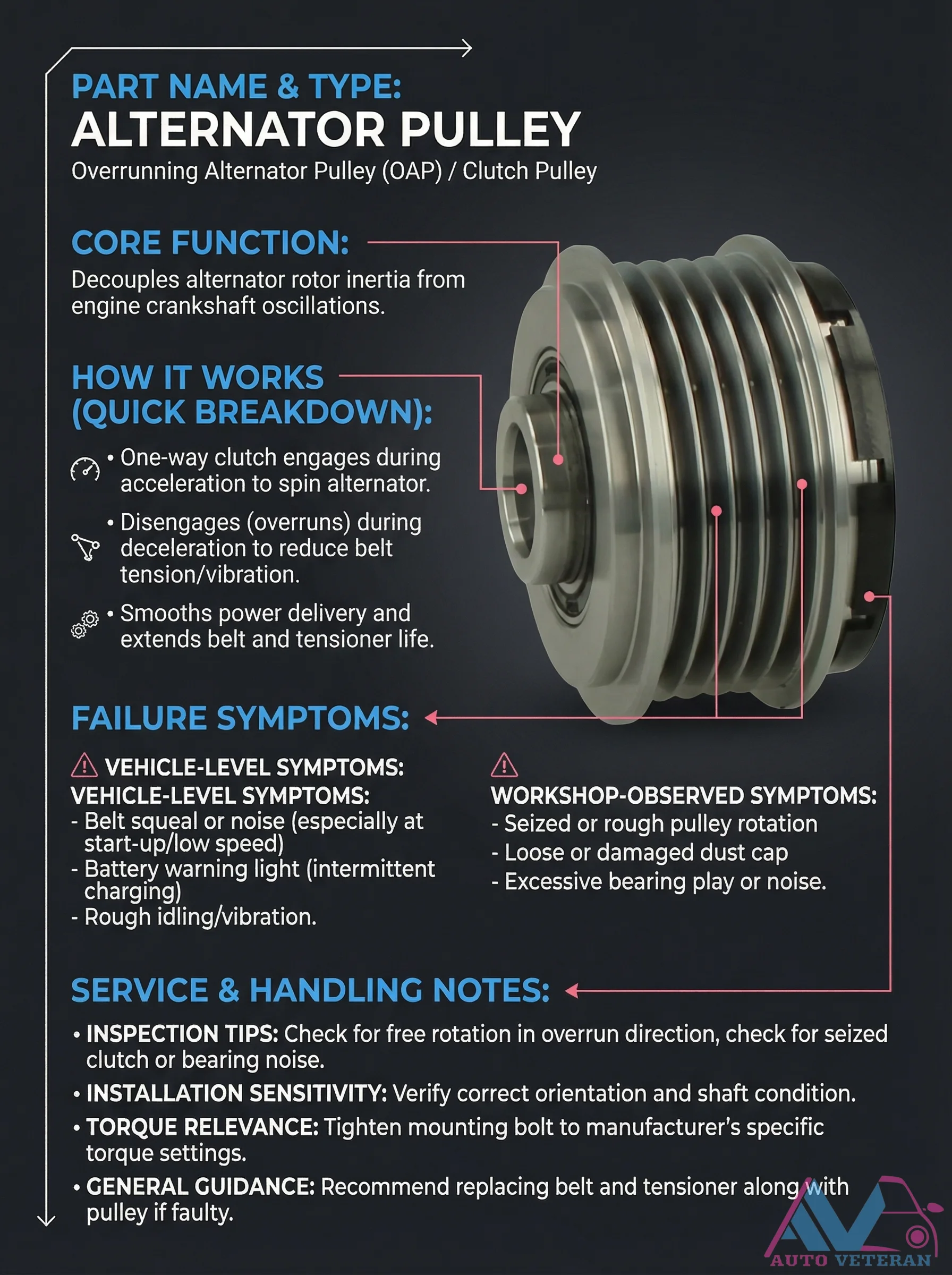
Alternator OAP Pulley Failure Symptoms and Inspection
The Overrunning Alternator Pulley, or OAP, is a critical component that decouples alternator rotor inertia from engine crankshaft oscillations. This one way clutch engages during acceleration to spin the alternator and disengages during deceleration to reduce belt tension and vibration, smoothing power delivery while extending belt and tensioner life. When this pulley fails, vehicle level symptoms include belt squeal or noise especially at startup or low speed, battery warning light with intermittent charging issues, and rough idling with vibration. Workshop observed symptoms include seized or rough pulley rotation, loose or damaged dust caps, and excessive bearing play or noise. Proper inspection involves checking for free rotation in the overrun direction while listening for seized clutch or bearing noise. Installation requires verifying correct orientation and shaft condition, tightening the mounting bolt to manufacturer specific torque settings, and generally replacing the belt and tensioner along with the pulley if faulty.
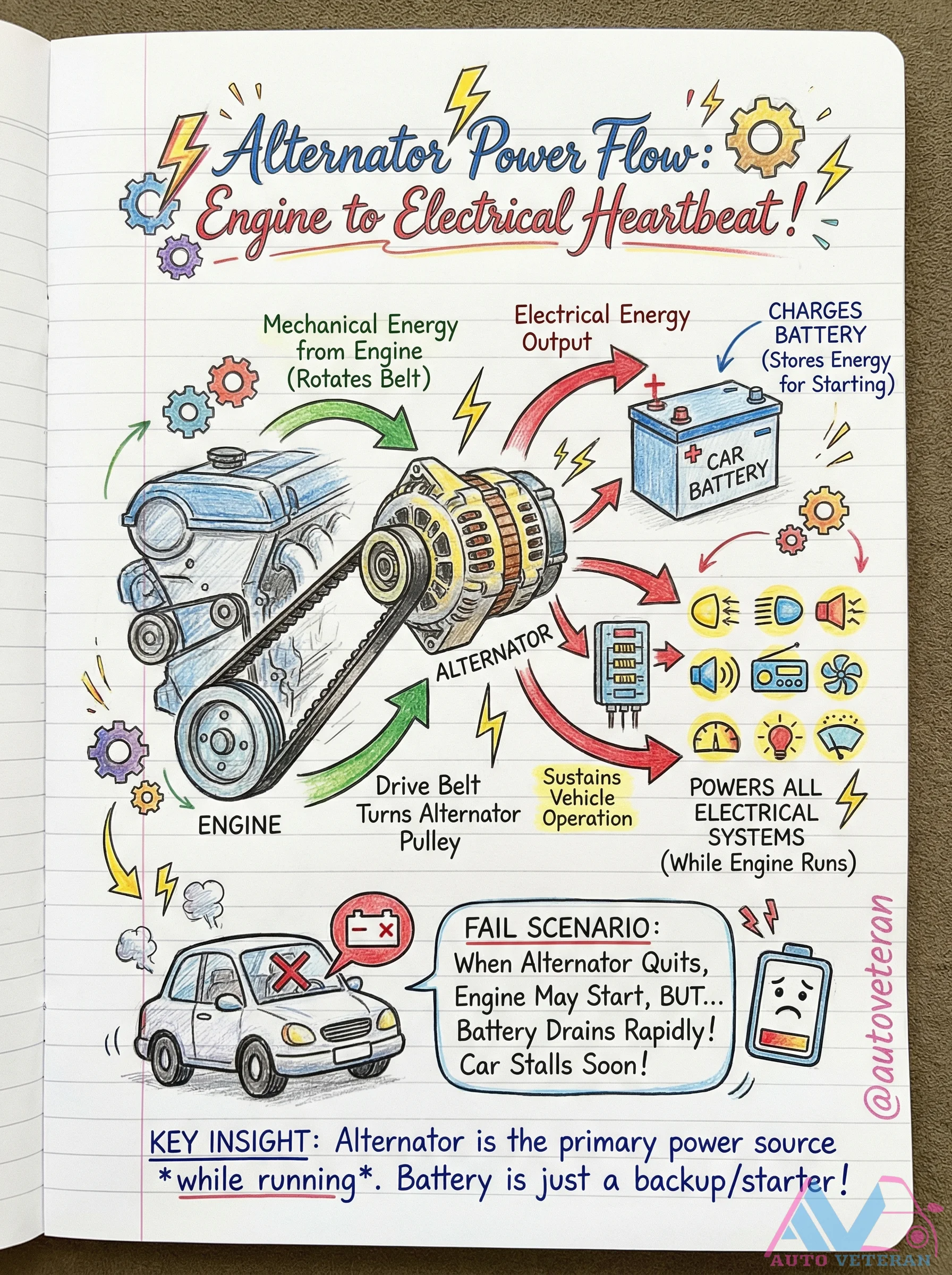
Alternator Power Flow and Failure Scenario
The alternator serves as the primary electrical power source while the engine runs, converting mechanical energy from the drive belt into electrical energy to power all vehicle systems and recharge the battery. When the alternator fails, the battery rapidly drains as it becomes the sole power source, leading to engine stall soon after starting. This critical insight highlights why the alternator is essential for sustained operation, not just for starting the vehicle.
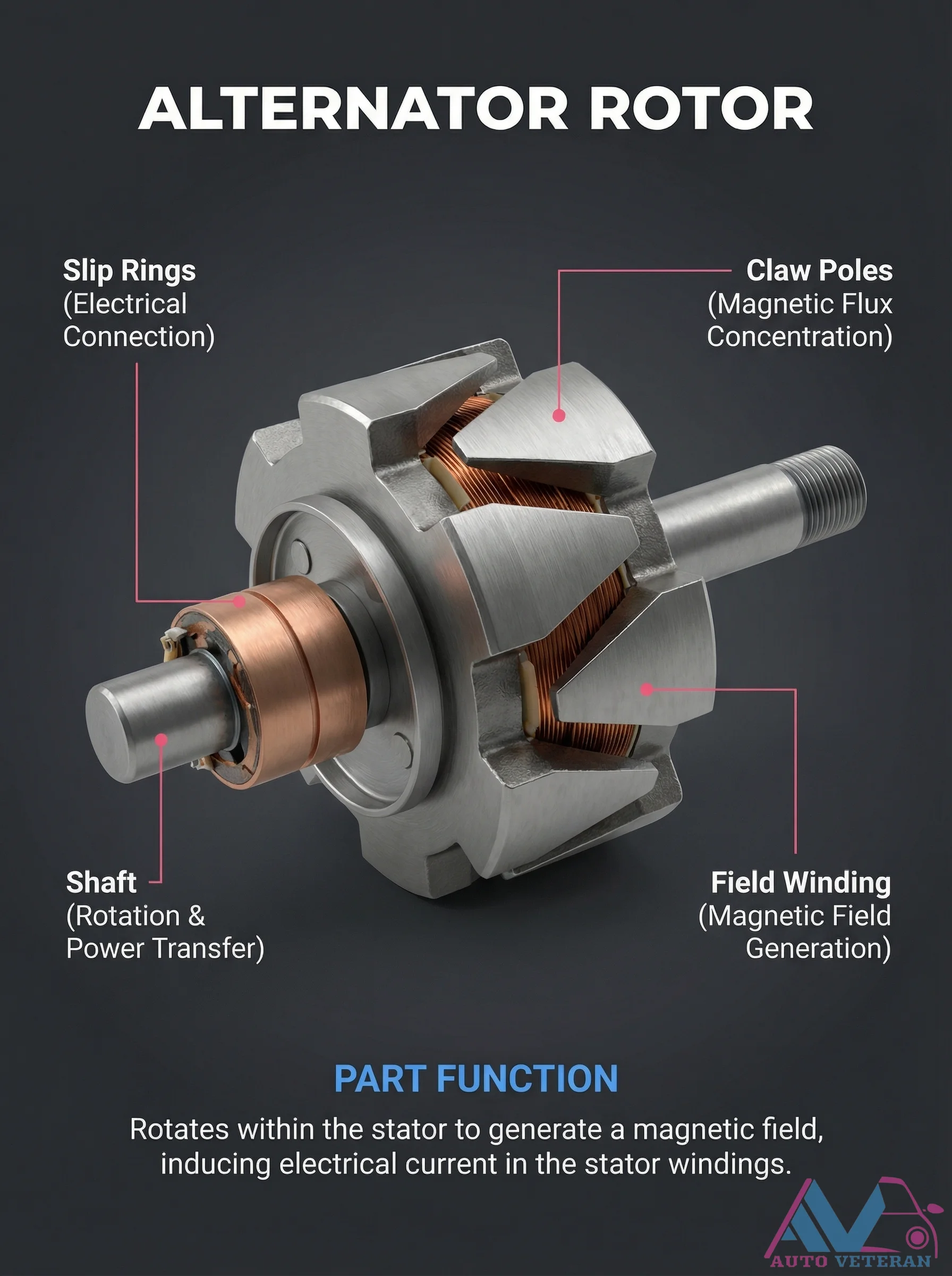
Alternator Rotor Components and Their Functions
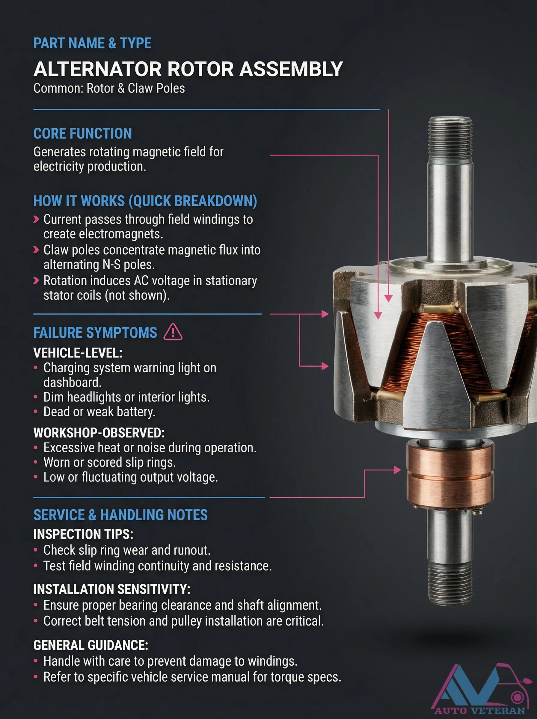
The alternator rotor is the rotating heart of your vehicle's charging system, featuring slip rings for electrical connection, claw poles for magnetic flux concentration, a shaft for power transfer, and a field winding that generates the magnetic field. As it spins within the stator, this assembly induces electrical current in the stator windings, converting mechanical energy into the electricity that powers your car's electrical systems and recharges the battery.
Alternator Rotor Failure Symptoms and Inspection Tips
When an alternator rotor assembly fails, vehicle level symptoms include a charging system warning light, dim headlights or interior lights, and a dead or weak battery. Workshop observations reveal excessive heat or noise during operation, scored slip rings, and low or fluctuating output voltage. Proper inspection involves checking slip ring wear and runout, testing field winding continuity and resistance, ensuring proper bearing clearance and shaft alignment, and maintaining correct belt tension and pulley installation. Always handle with care to prevent damage to windings and refer to the specific vehicle service manual for torque specifications.
Alternator Rotor Field Assembly Failure Symptoms
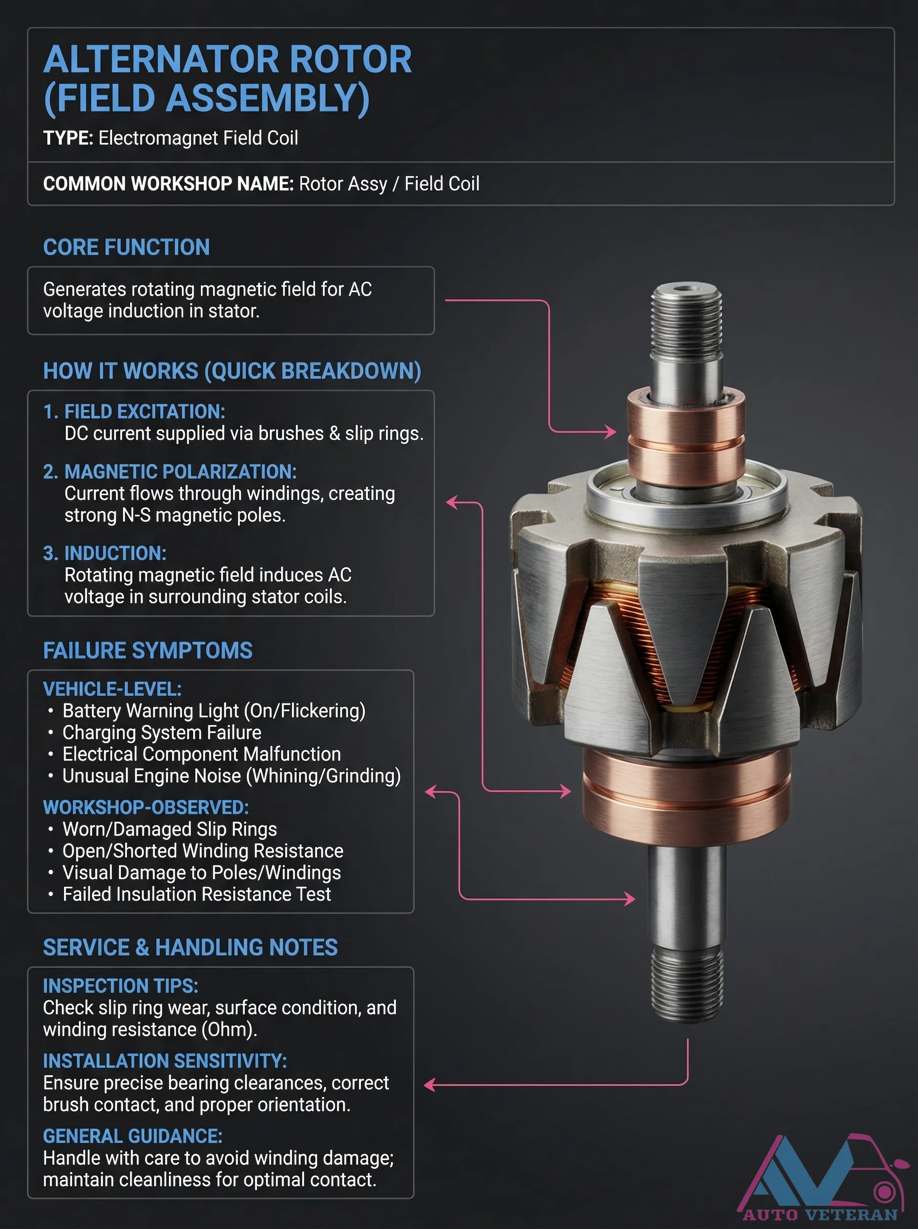
The alternator rotor, also known as the field assembly, is an electromagnet that generates a rotating magnetic field to induce AC voltage in the stator. When this component fails, symptoms manifest at both the vehicle and workshop levels. Drivers may notice the battery warning light illuminating or flickering, charging system failure, electrical component malfunctions, or unusual engine noises like whining or grinding. Technicians can identify issues through worn or damaged slip rings, open or shorted windings, visual damage to poles or windings, or failed insulation resistance tests. Proper inspection includes checking slip ring wear, surface condition, and winding resistance in ohms, while installation requires precise bearing clearances, correct brush contact, and proper orientation to avoid winding damage and ensure optimal performance.
Alternator Slip Rings Failure Symptoms and Inspection
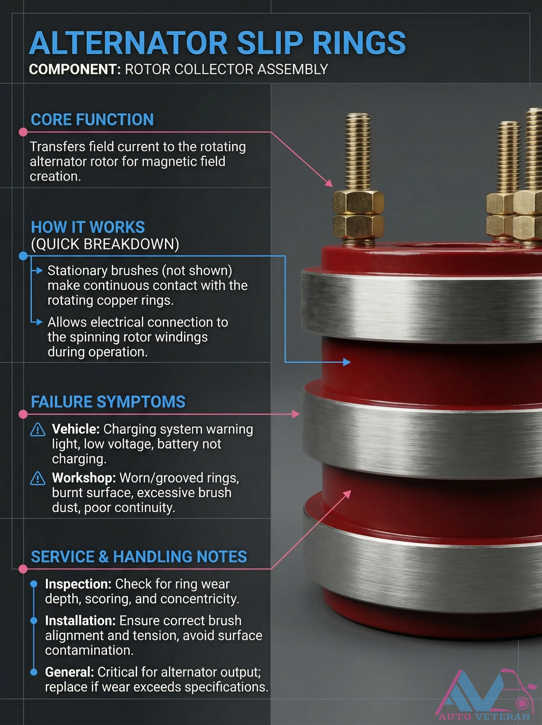
The slip rings, part of the rotor collector assembly, transfer field current to create the alternator's magnetic field. When these copper rings fail, drivers experience charging system warning lights and low voltage, while technicians find worn or grooved rings, burnt surfaces, excessive brush dust, and poor continuity. Proper inspection requires checking wear depth, scoring, and concentricity, while installation demands correct brush alignment and tension to avoid surface contamination. These components are critical for alternator output and must be replaced if wear exceeds specifications.
Alternator Slip Rings Failure Symptoms and Service Notes
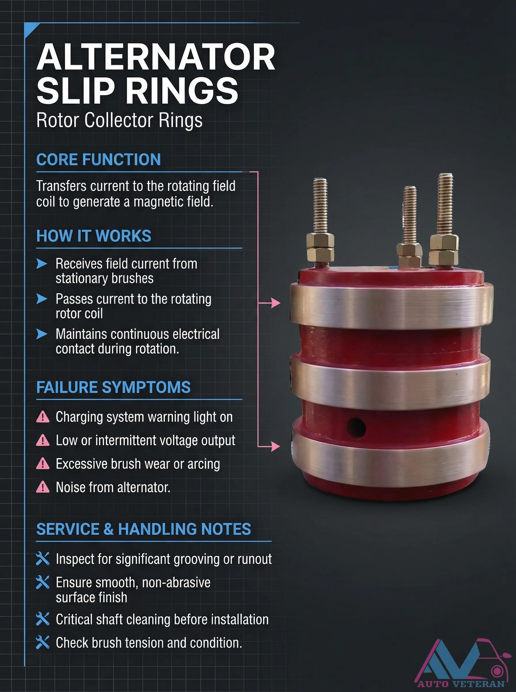
Alternator slip rings, also known as rotor collector rings, serve the core function of transferring current to the rotating field coil to generate a magnetic field. They work by receiving field current from stationary brushes and passing it to the rotating rotor coil while maintaining continuous electrical contact during operation. When these components fail, symptoms include the charging system warning light illuminating, low or intermittent voltage output, excessive brush wear, and noise emanating from the alternator. Proper service and handling involve inspecting for significant grooving or runout, ensuring a smooth, non-abrasive surface finish, performing critical shaft cleaning before installation, and checking brush tension condition to prevent issues like arcing and premature wear.
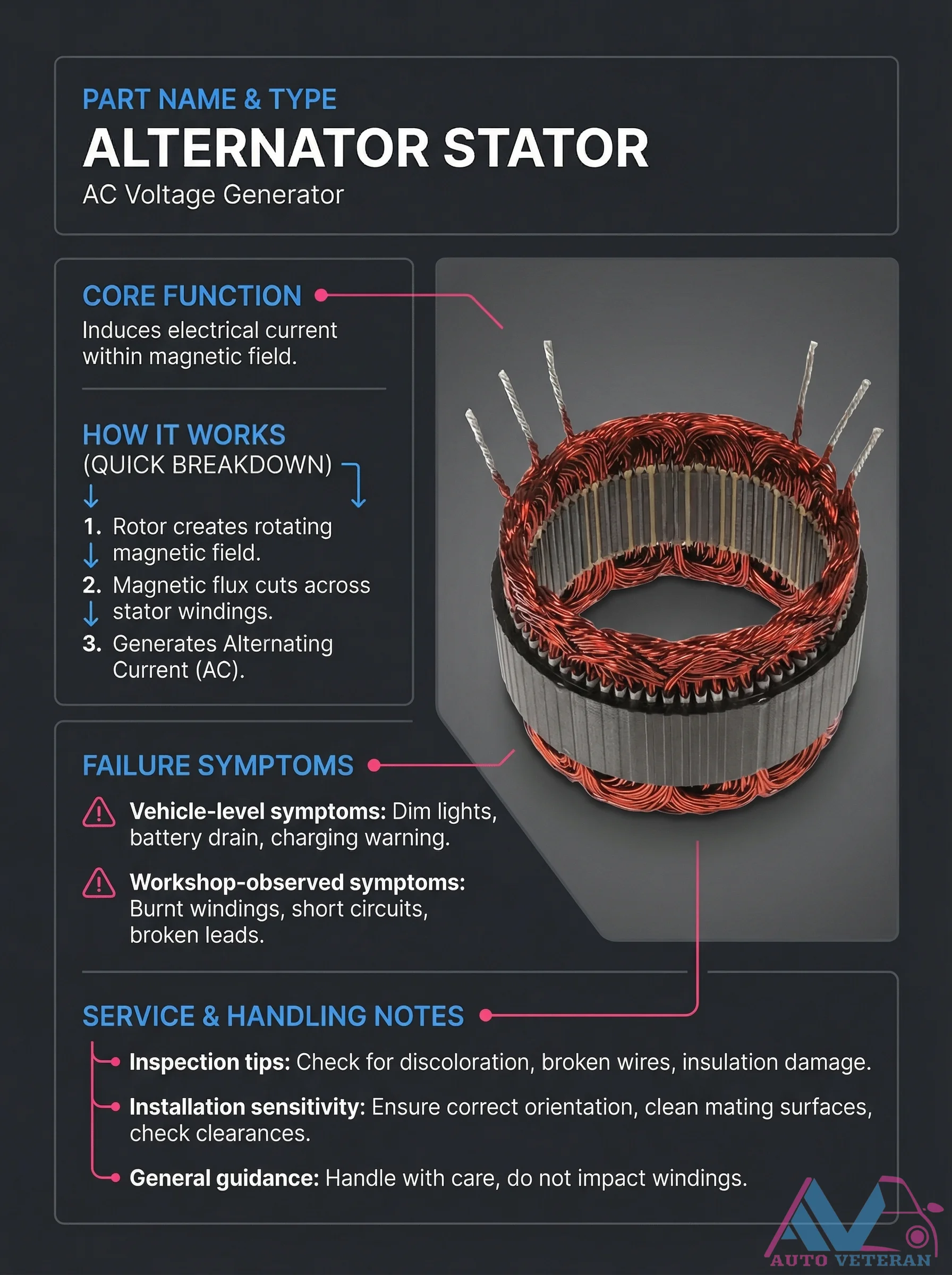
Alternator Stator Failure Symptoms and Inspection
When an alternator stator fails, vehicle symptoms include dim lights, battery drain, and charging warnings, while workshop observations reveal burnt windings, short circuits, or broken leads. Proper inspection involves checking for discoloration, broken wires, and insulation damage, with careful handling to avoid impacting the windings during service.
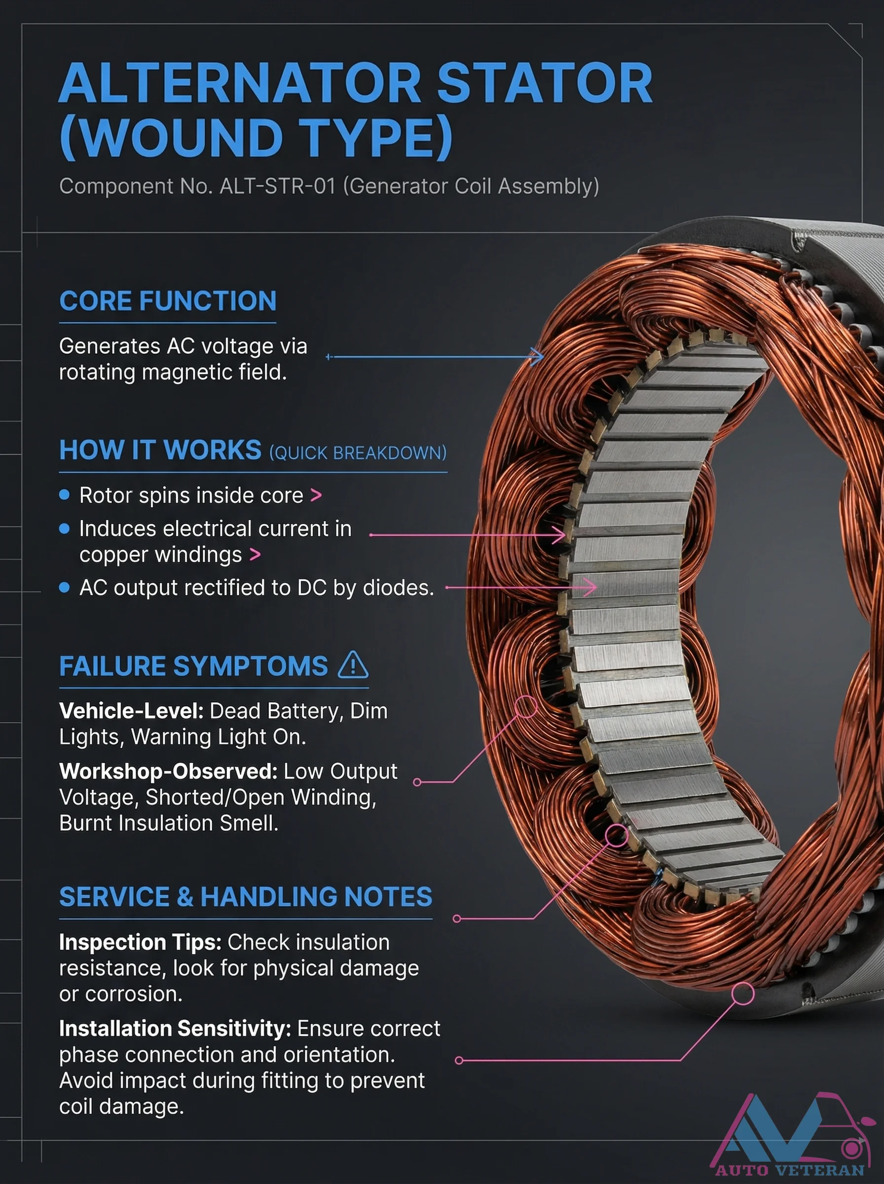
Alternator Stator Wound Type Failure Symptoms
The wound type alternator stator, identified as component ALT-STR-01, generates AC voltage through its copper windings as the rotor spins within the core. When this critical component fails, vehicle level symptoms include a dead battery, dim lights, and warning lights illuminating on the dashboard. In the workshop, technicians observe low output voltage, shorted or open windings, and the distinct smell of burnt insulation. Proper service requires checking insulation resistance, inspecting for physical damage or corrosion, ensuring correct phase connection and orientation during installation, and handling carefully to prevent coil damage from impact.
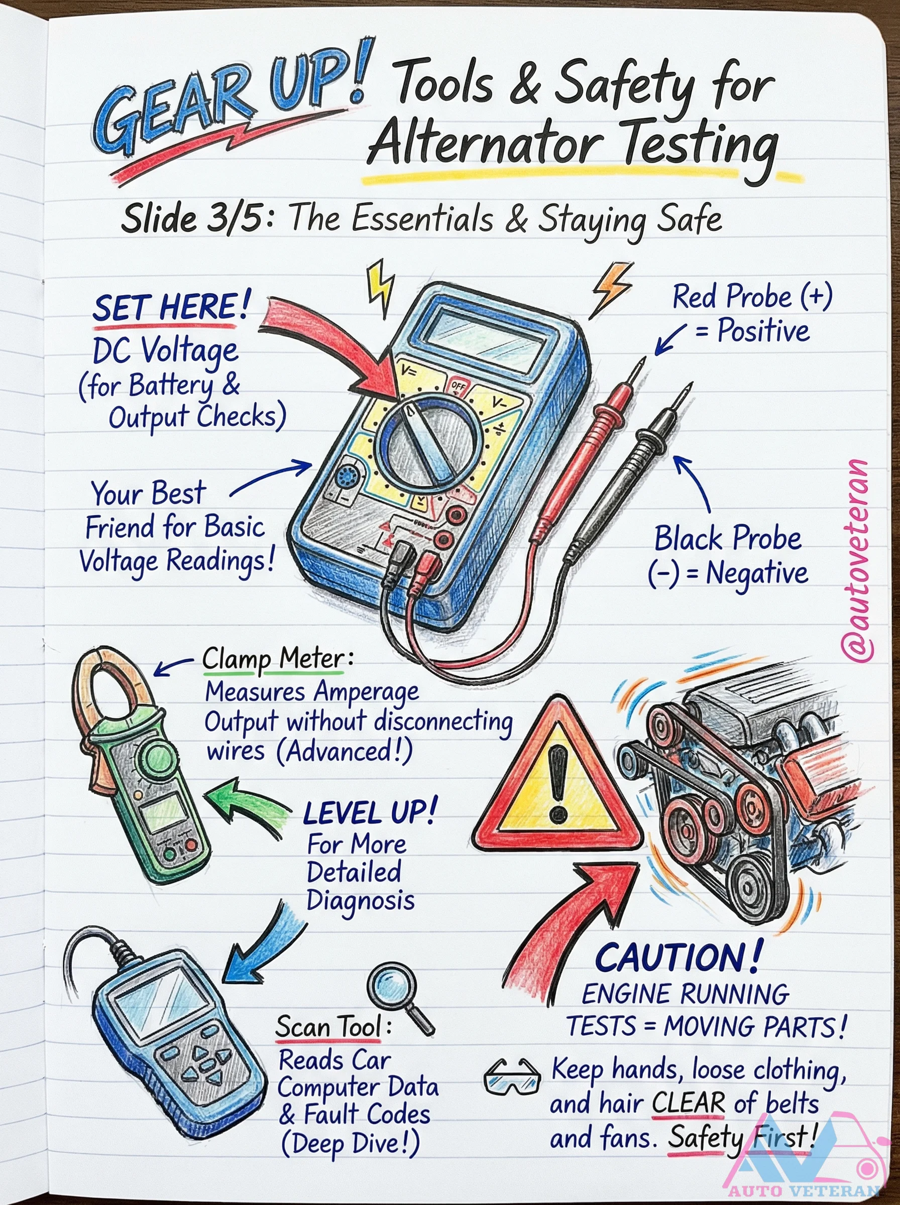
Alternator Testing Tools and Safety Essentials
Proper alternator testing requires specific tools and strict safety protocols. Essential equipment includes a multimeter with red and black probes for DC voltage readings, a clamp meter for measuring amperage output without disconnecting wires, and a scan tool for accessing car computer data and fault codes. Critical safety precautions must be observed when testing a running engine, including keeping hands, loose clothing, and hair clear of moving belts and fans. Always verify battery condition before proceeding with alternator diagnostics.
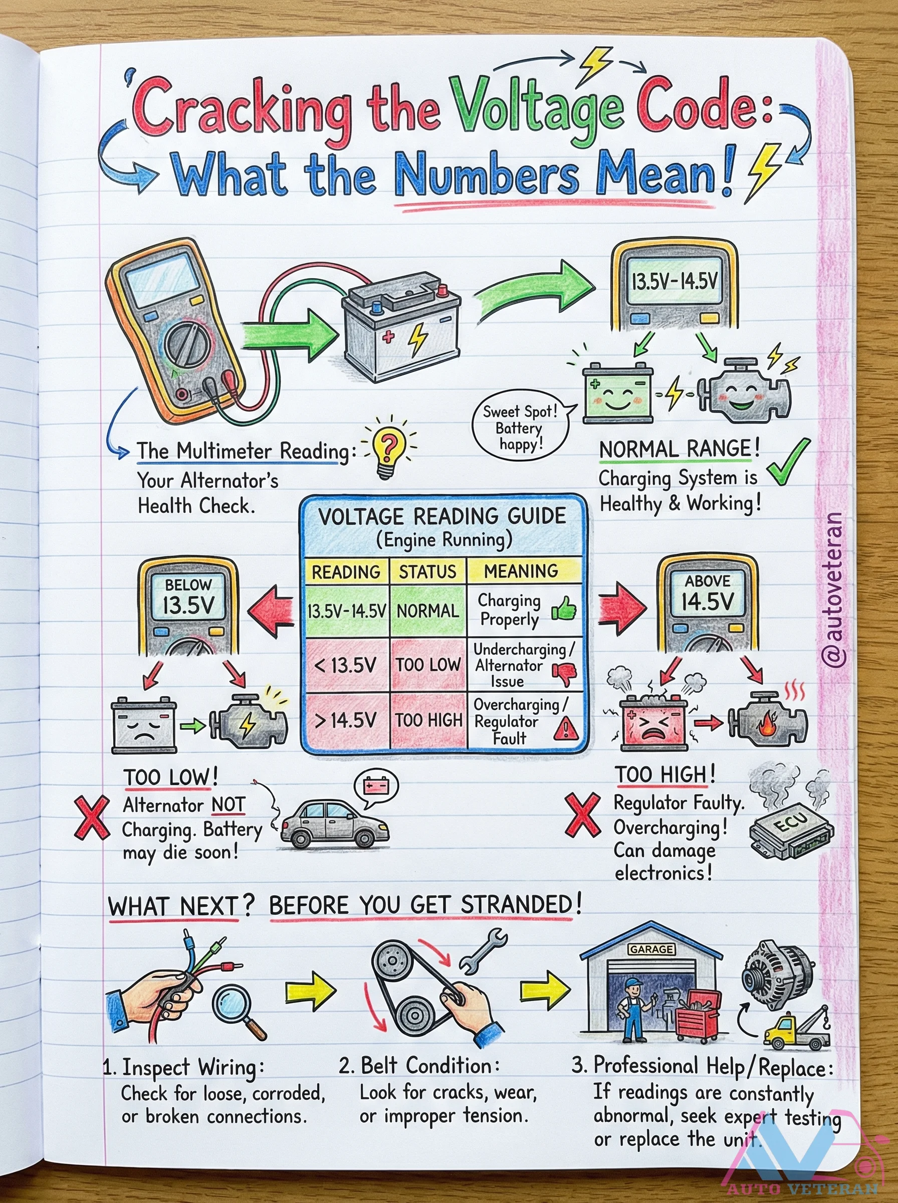
Alternator Voltage Reading Guide for Health Check
Understanding your alternator's voltage output is crucial for diagnosing charging system health. The normal range while the engine is running falls between 13.5V and 14.5V, indicating proper charging. Readings below 13.5V suggest undercharging, often due to alternator issues, which can lead to a dead battery. Readings above 14.5V indicate overcharging, typically caused by a faulty voltage regulator, potentially damaging sensitive electronics. This guide provides clear steps for interpreting multimeter readings, including inspecting wiring for loose or corroded connections, checking belt condition for cracks or improper tension, and seeking professional help if abnormal readings persist. Regular voltage checks can prevent unexpected breakdowns and protect your vehicle's electrical components.