Interactive Explorer
OBD-II Check Engine Light Diagnosis and DTC Analysis
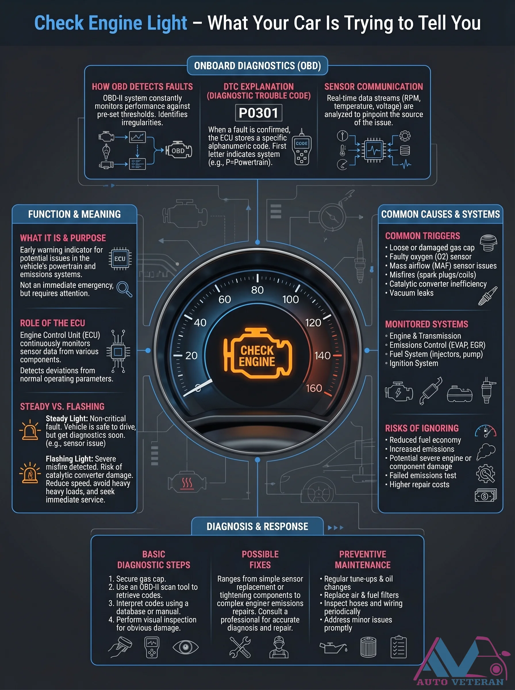
Your vehicle's onboard diagnostics system constantly monitors performance through real-time data streams like RPM and voltage, comparing them against preset thresholds to detect irregularities. When a fault is confirmed, the Engine Control Unit stores a specific Diagnostic Trouble Code, with the first letter indicating the affected system such as P for powertrain. Common triggers include loose gas caps, faulty oxygen sensors, mass airflow sensor issues, misfires, catalytic converter inefficiency, and vacuum leaks. A steady check engine light signals a non-critical fault requiring attention, while a flashing light indicates severe issues like misfires that risk catalytic converter damage. Diagnosis involves using a scan tool to retrieve codes, interpreting them with a database, and performing fixes ranging from simple sensor replacements to complex repairs. Ignoring these warnings can lead to reduced fuel economy, increased emissions, failed tests, and higher repair costs.
OBD2 Fast Diagnosis Guide for Sensors and Catalytic Converter
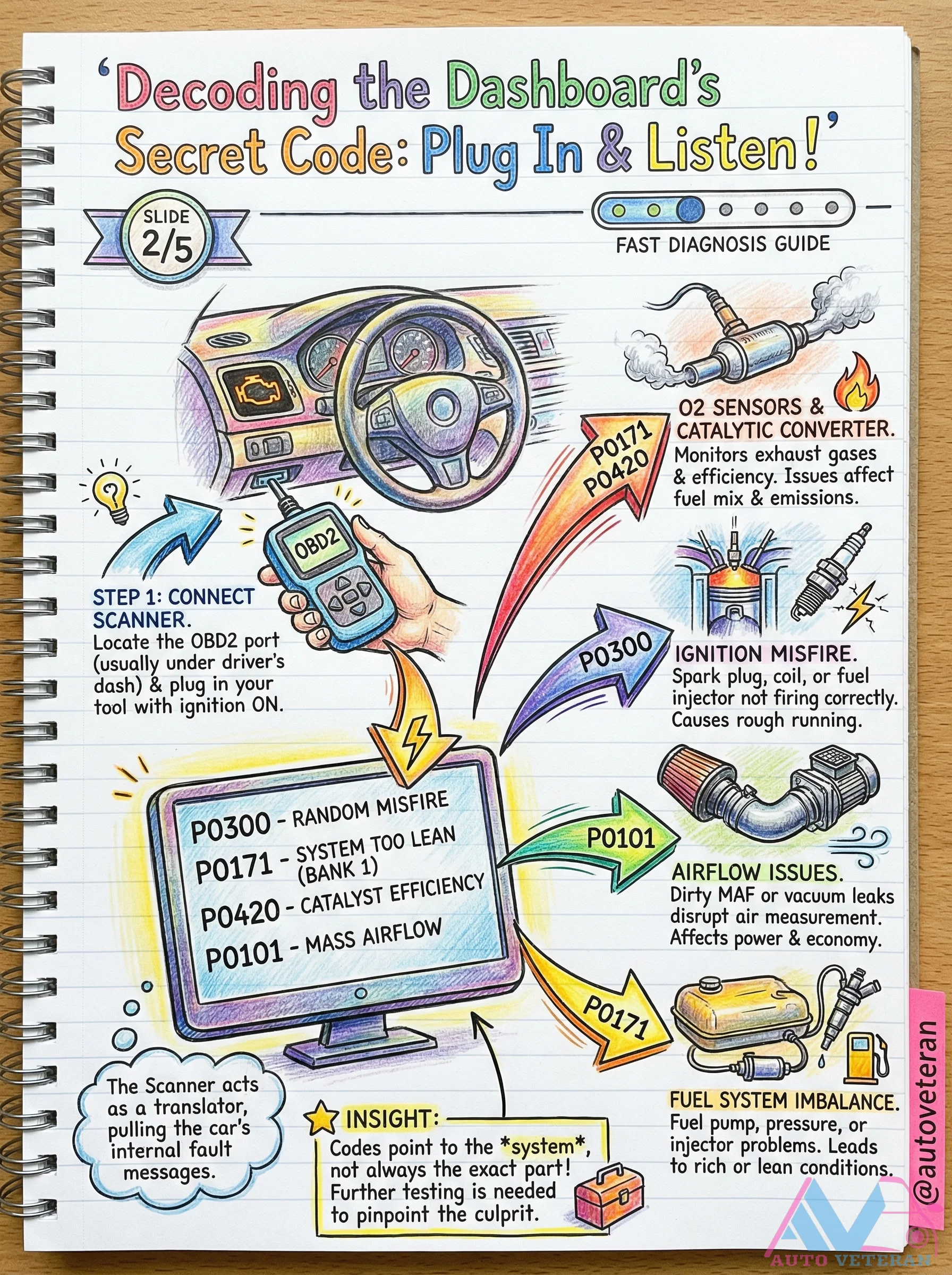
This guide provides a rapid diagnostic approach for common OBD2 issues related to sensors and the catalytic converter, focusing on interpreting fault codes like P0101, P0171, P0300, and P0420 to identify problems with air measurement, fuel mixture, ignition misfires, and catalyst efficiency.
OBD2 Scanner Fault Code Interpretation Guide
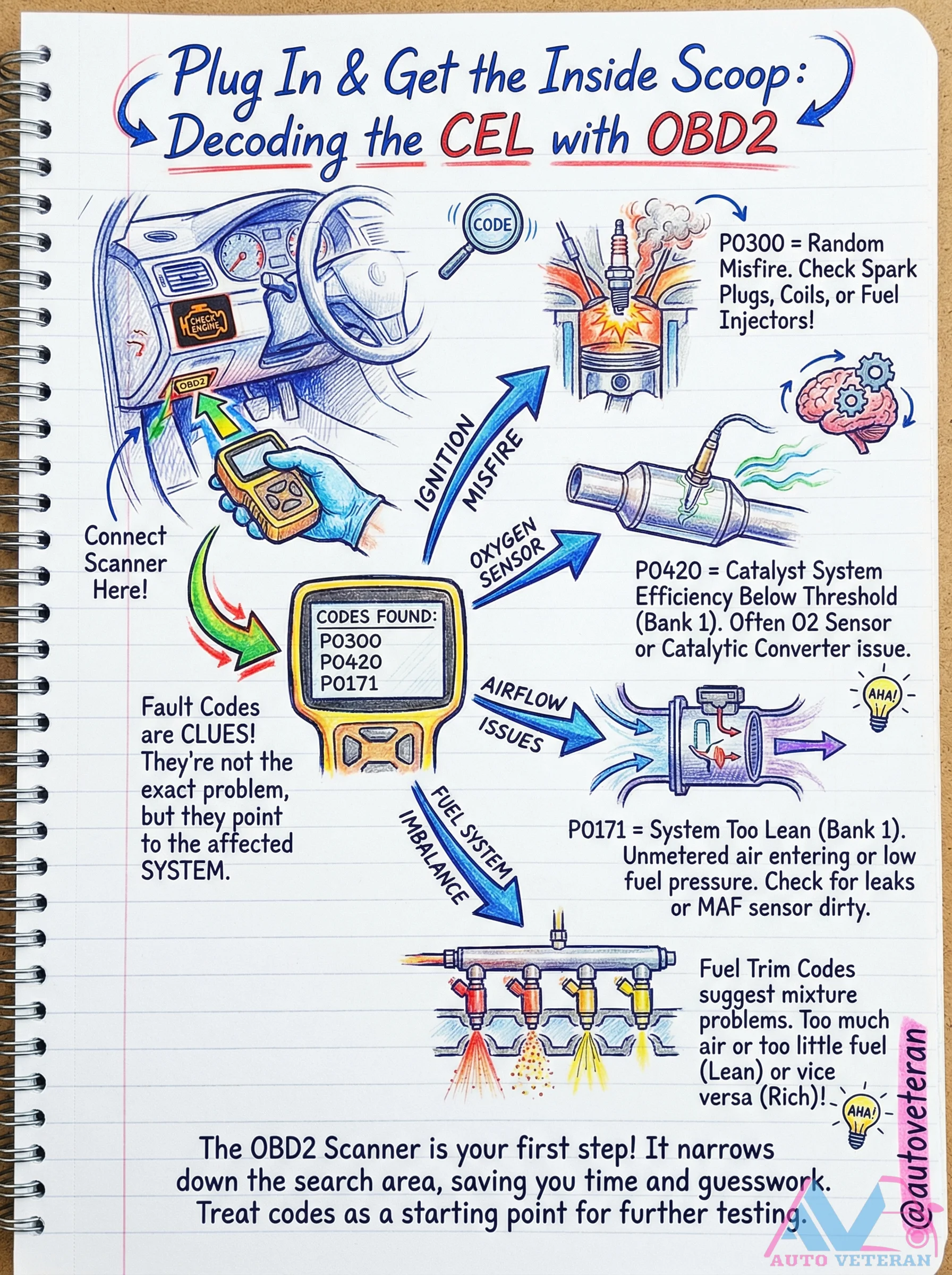
Understanding how to interpret OBD2 scanner fault codes is crucial for effective automotive diagnostics; codes like P0300 for random misfires, P0420 for catalytic converter efficiency, and P0171 for lean conditions provide specific clues rather than definitive solutions. These codes point toward potential issues with spark coils, fuel injectors, oxygen sensors, or air intake leaks, guiding you to targeted testing areas like the MAF sensor or fuel system pressure. Treating fault codes as starting points for further investigation saves time and reduces guesswork, helping you systematically address underlying problems in your vehicle's engine management system.
Oil Contamination in Turbochargers Causes Bearing Damage
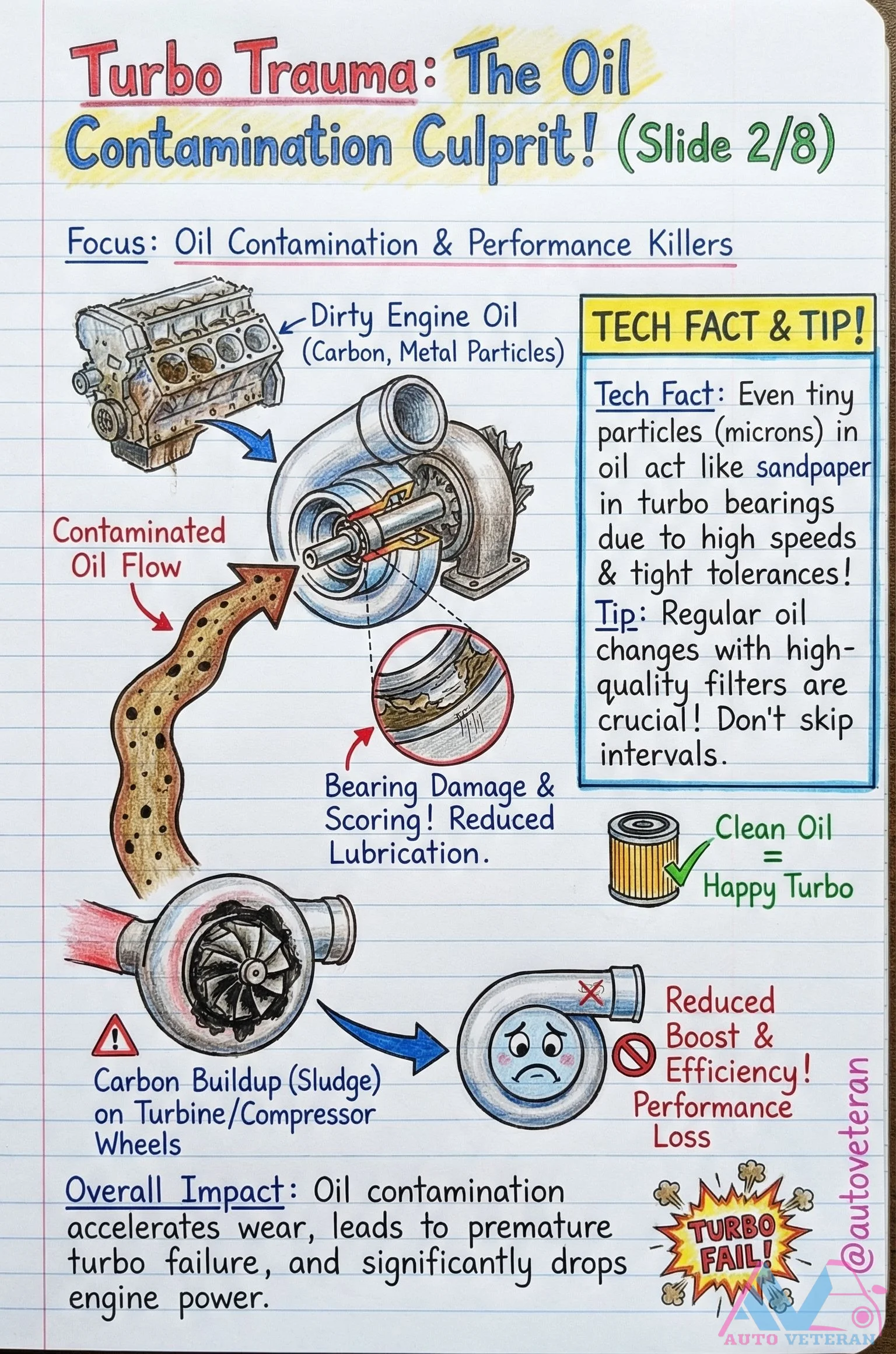
Contaminated engine oil containing carbon and metal particles acts as an abrasive agent within turbocharger bearings, accelerating wear through microscopic sandpaper-like action. This contamination occurs due to high oil flow rates and tight bearing tolerances in turbo systems. The result is bearing damage, reduced lubrication efficiency, and compromised turbine and compressor wheel performance. Ultimately, oil contamination leads to premature turbo failure, significant power loss, and decreased overall engine efficiency. Regular oil changes with high-quality filters are essential to prevent this destructive process.
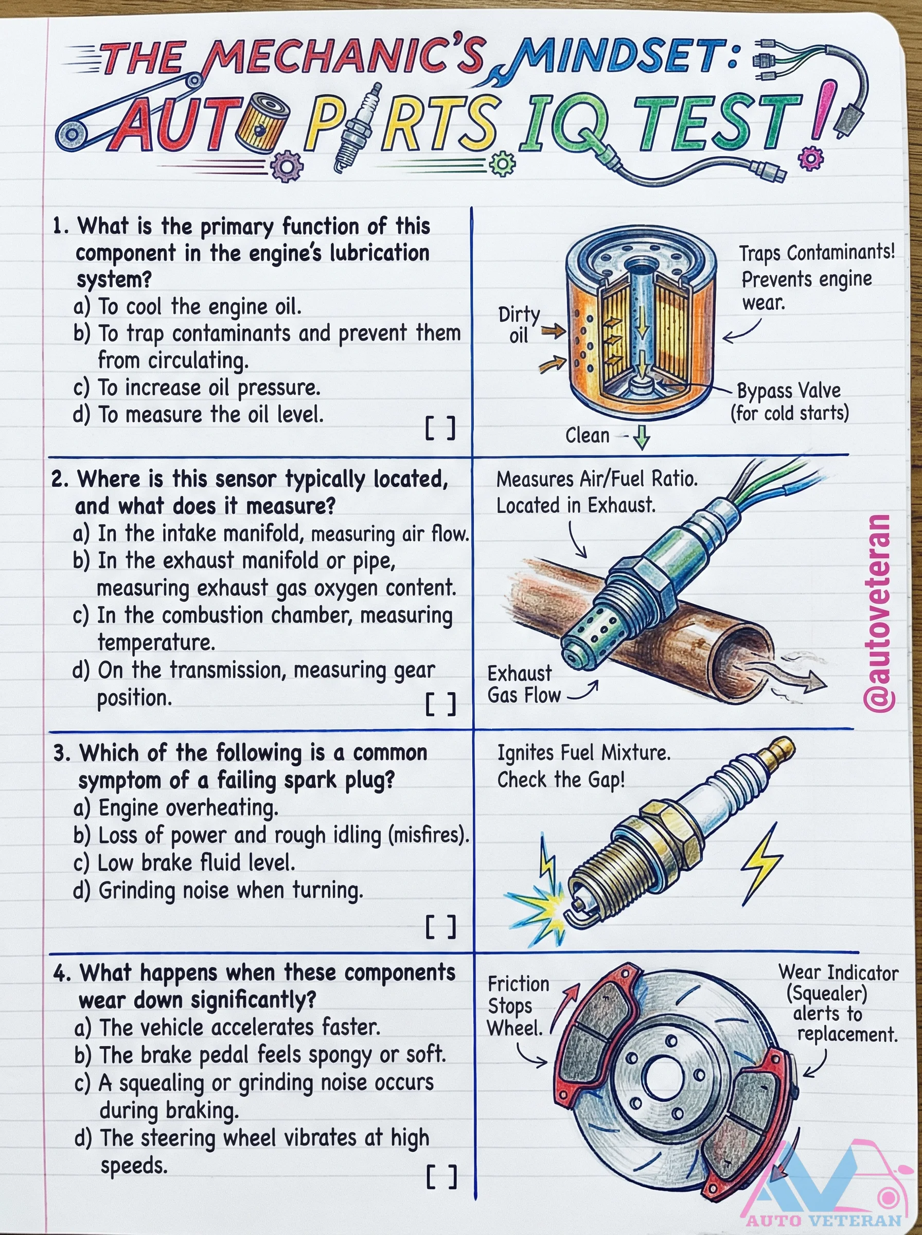
Oil Filter Function and Contaminant Trapping
The primary role of an oil filter is to trap contaminants and prevent them from circulating through the engine's lubrication system; this critical function protects internal components from wear and ensures clean oil flows to vital engine parts. A bypass valve activates during cold starts or when the filter becomes clogged, allowing oil to continue circulating while maintaining system integrity. Understanding this component's operation helps maintain engine longevity and performance by filtering out harmful particles that could otherwise cause significant damage.
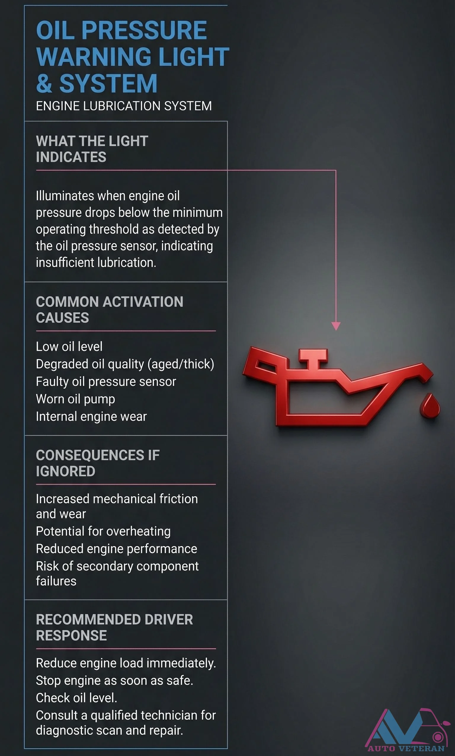
Oil Pressure Warning Light Activation Causes and Consequences
When your dashboard's oil pressure warning light illuminates, it signals that engine oil pressure has fallen below the minimum operating threshold, as detected by the oil pressure sensor. This critical alert indicates insufficient lubrication within the engine's lubrication system. Common causes for this activation include low oil level, degraded oil quality from aging or thickening, a faulty oil pressure sensor, a worn oil pump, or internal engine wear. Ignoring this warning can lead to increased mechanical friction and wear, potential engine overheating, reduced performance, and risk of secondary component failures. The recommended driver response is to immediately reduce engine load, stop the engine as soon as it is safe to do so, check the oil level, and consult a qualified technician for diagnostic scanning and repair.
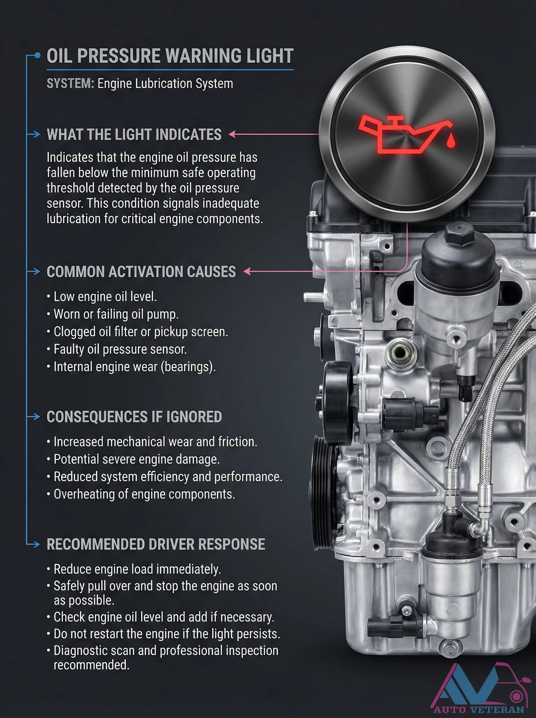
Oil Pressure Warning Light Activation Causes and Response
When the oil pressure warning light illuminates on your dashboard, it signals that engine oil pressure has dropped below safe operating levels, threatening critical components with inadequate lubrication. Common triggers include low oil levels, a failing oil pump, clogged filters or pickup screens, faulty pressure sensors, or internal engine wear from bearings. Ignoring this warning can lead to increased mechanical friction, severe engine damage, reduced efficiency, performance loss, and component overheating. The recommended response involves immediately reducing engine load, safely pulling over to stop the engine, checking and adding oil if needed, avoiding restart if the light persists, and seeking professional diagnostic inspection.
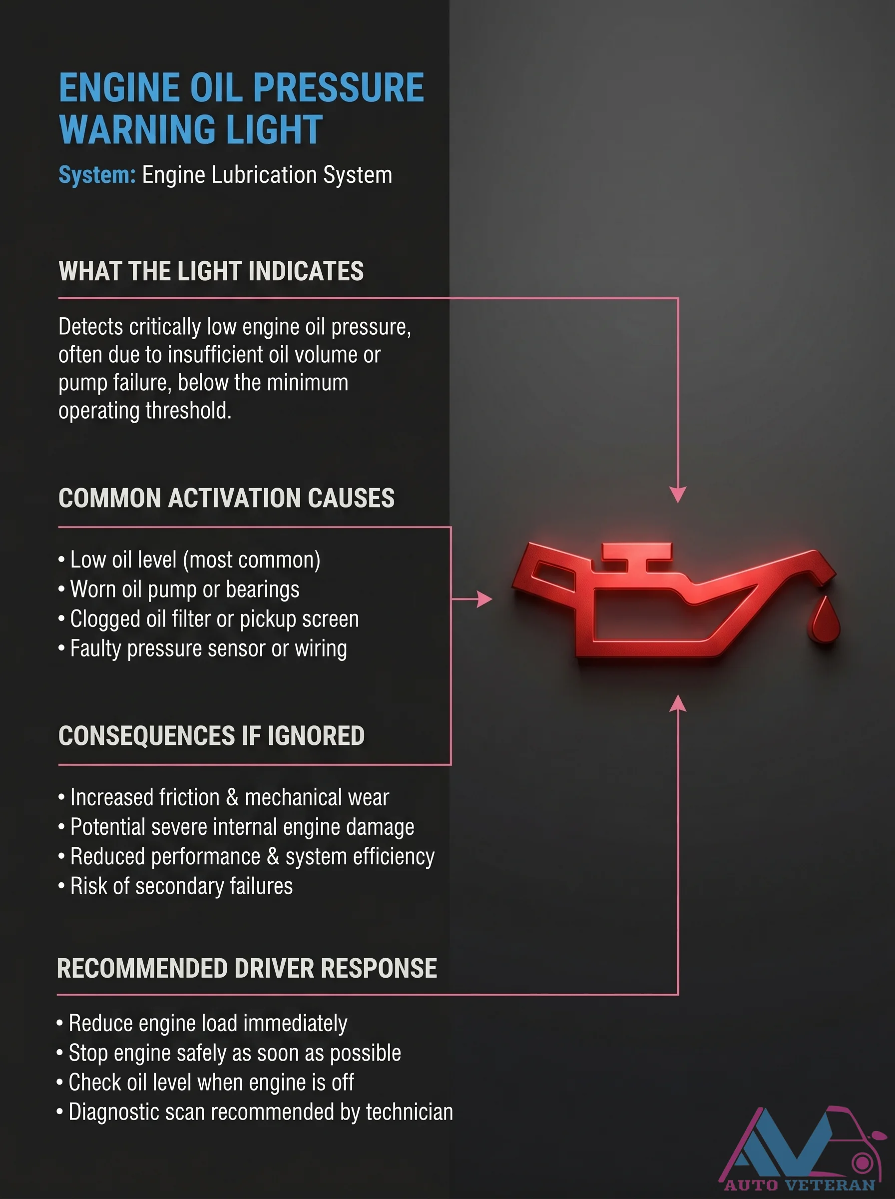
Oil Pressure Warning Light Causes
When the engine oil pressure warning light illuminates, it means your engine's lubrication system has detected critically low oil pressure, often from low oil level, a worn oil pump or bearings, a clogged oil filter or pickup screen, or a faulty pressure sensor or wiring. Ignoring this warning can lead to increased friction, severe internal engine damage, reduced performance, and risk of secondary failures. Drivers should immediately reduce engine load, stop safely, check oil level when the engine is off, and have a technician perform a diagnostic scan.
Oil Pressure Warning Light Causes and Driver Response
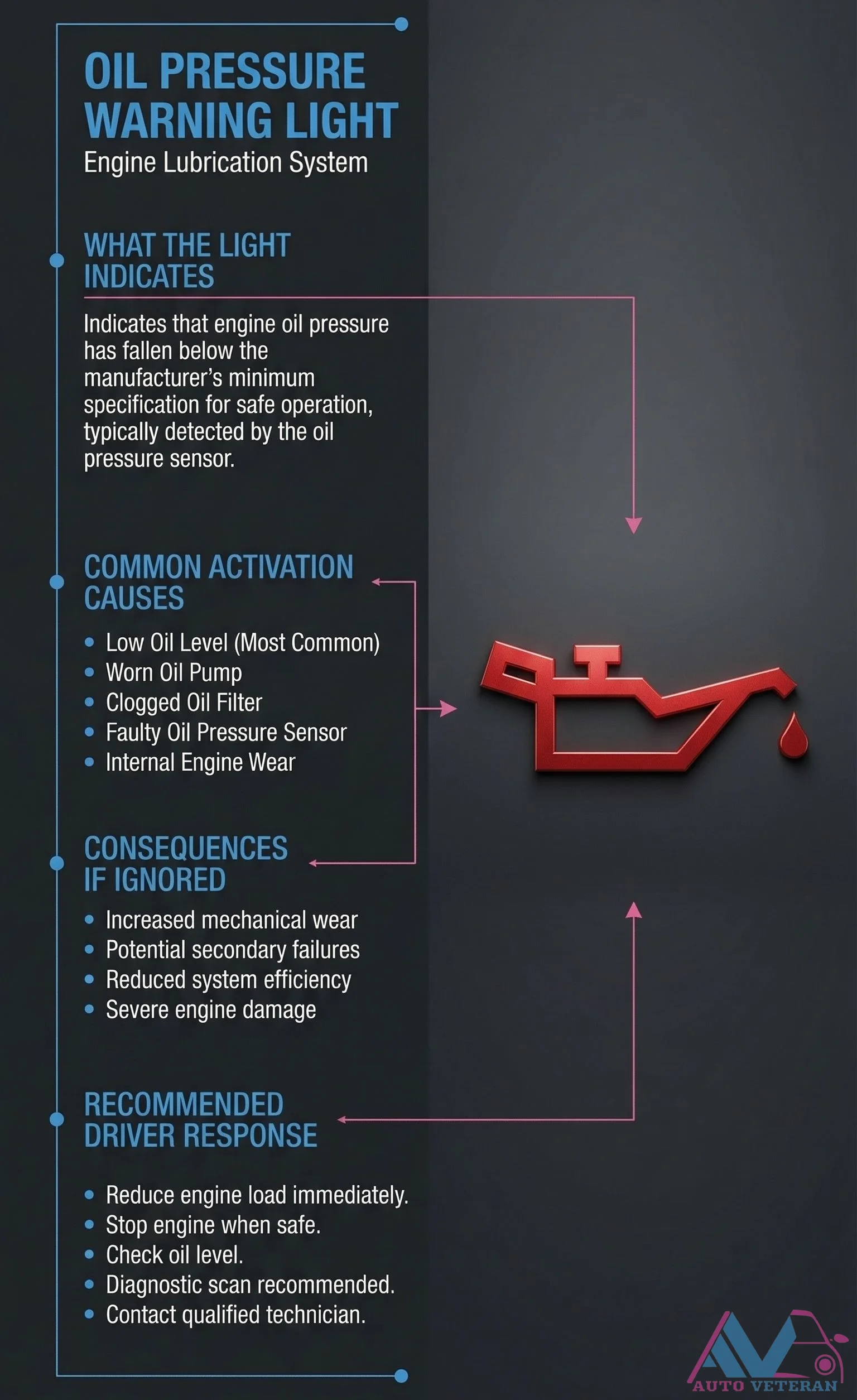
The oil pressure warning light illuminates when engine oil pressure drops below the manufacturer's minimum safe specification, typically detected by the oil pressure sensor. Common activation causes include low oil level, worn oil pump, clogged oil filter, faulty oil pressure sensor, or internal engine wear. Ignoring this warning leads to increased mechanical wear, potential secondary failures, reduced system efficiency, and severe engine damage. Recommended driver response involves reducing engine load immediately, stopping the engine when safe, checking oil level, performing diagnostic scans, and contacting a qualified technician.
Overnight Battery Drain Diagnosis Guide
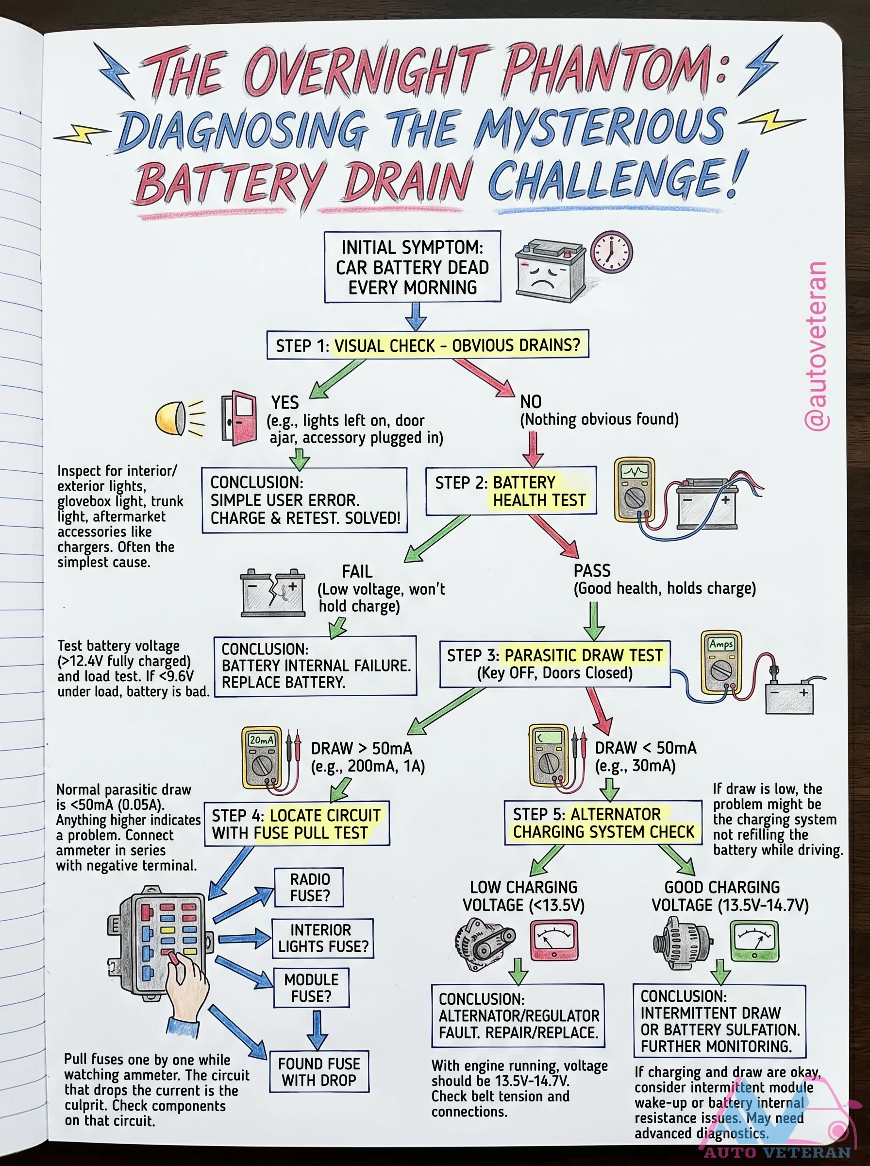
This comprehensive step by step guide walks you through diagnosing a mysterious overnight battery drain, from the initial symptom of a dead battery every morning to the final resolution. It covers the visual check for obvious drains, battery health test, parasitic draw test with ammeter, fuse pull test to locate the offending circuit, and alternator charging system check to distinguish between a parasitic draw, battery sulfation, or alternator regulator fault. Each step includes clear conclusions to help you efficiently solve the battery drain mystery without guesswork.
Overrunning Alternator Pulley Failure Symptoms and Service
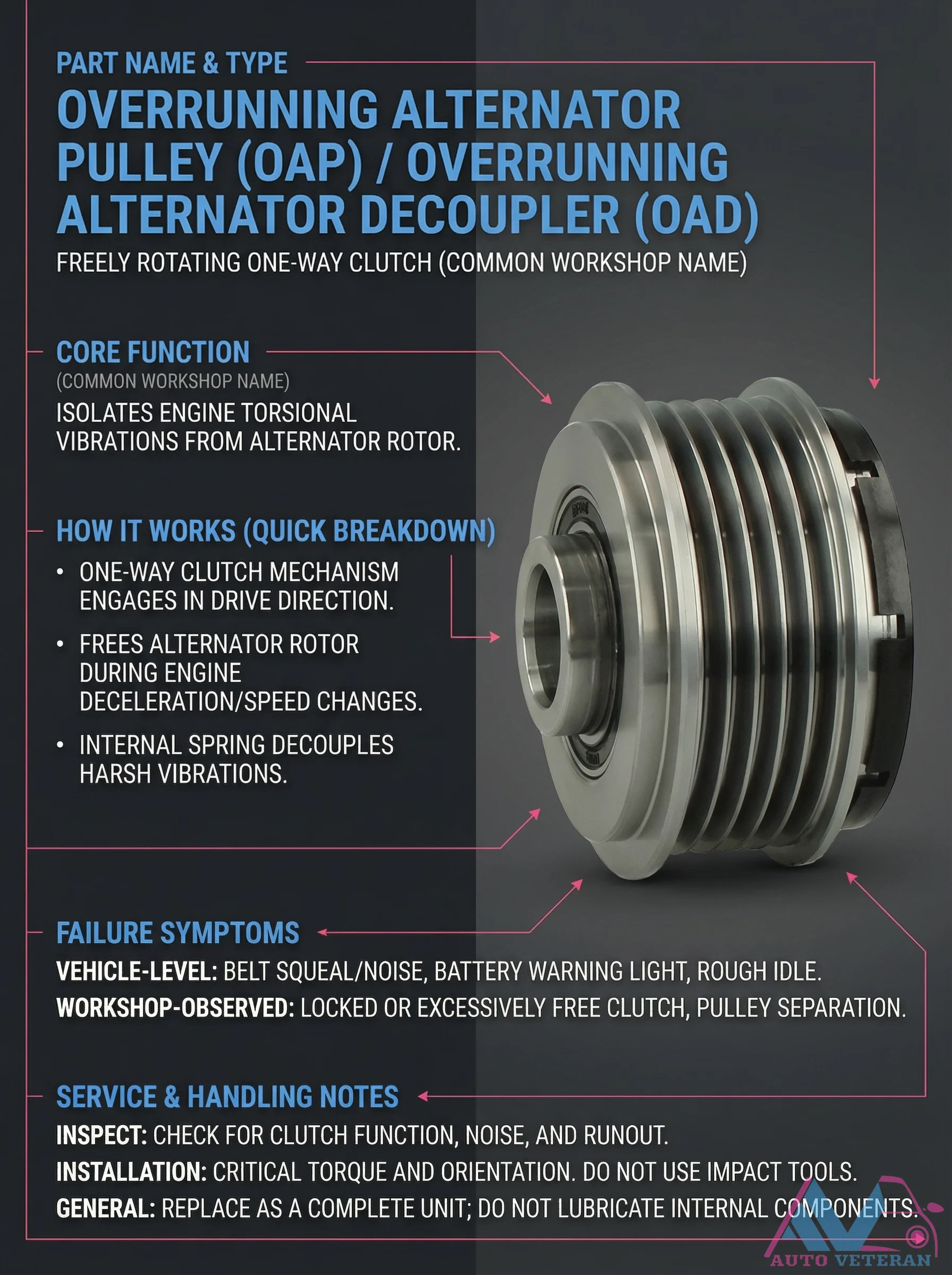
The overrunning alternator pulley, also known as an alternator decoupler, functions as a one way clutch mechanism that isolates engine torsional vibrations from the alternator rotor. It engages during drive direction but frees the alternator rotor during engine deceleration or speed changes, with an internal spring decoupling harsh vibrations. Common failure symptoms include belt squeal or noise, battery warning light illumination, and rough idle at the vehicle level, while workshop observations may reveal a locked or excessively free clutch, or pulley separation. Service requires careful inspection for clutch function, noise, and runout, with critical attention to proper torque and orientation during installation. Impact tools must not be used, and the unit should be replaced as a complete assembly without lubricating internal components.
Oxygen Sensor Air-Fuel Mixture Influence
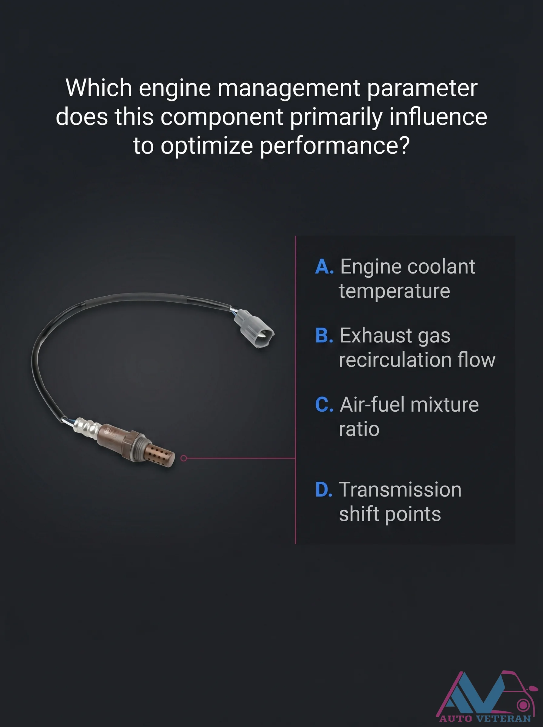
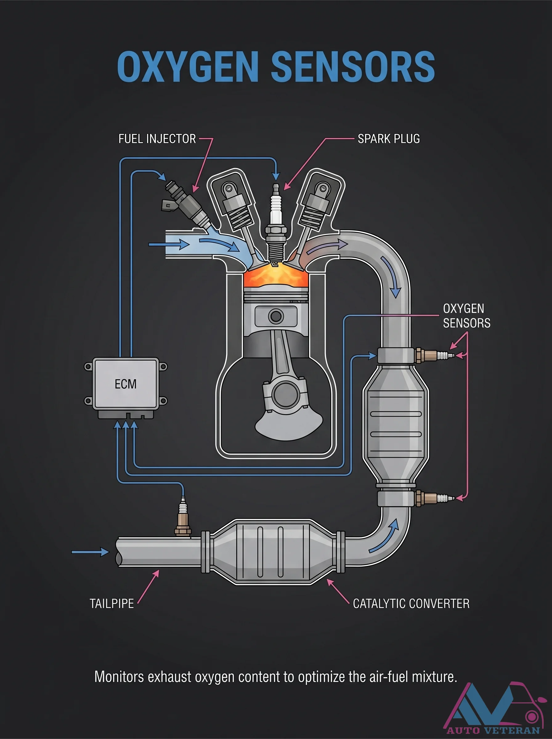
Engine parameters optimized by the oxygen sensor include the air fuel mixture ratio. By measuring residual oxygen in exhaust gases, the sensor provides feedback to adjust fuel injection timing and duration for stoichiometric combustion. This closed loop control maintains catalyst efficiency and reduces emissions while maximizing power output.
Oxygen Sensor Air-Fuel Ratio Control
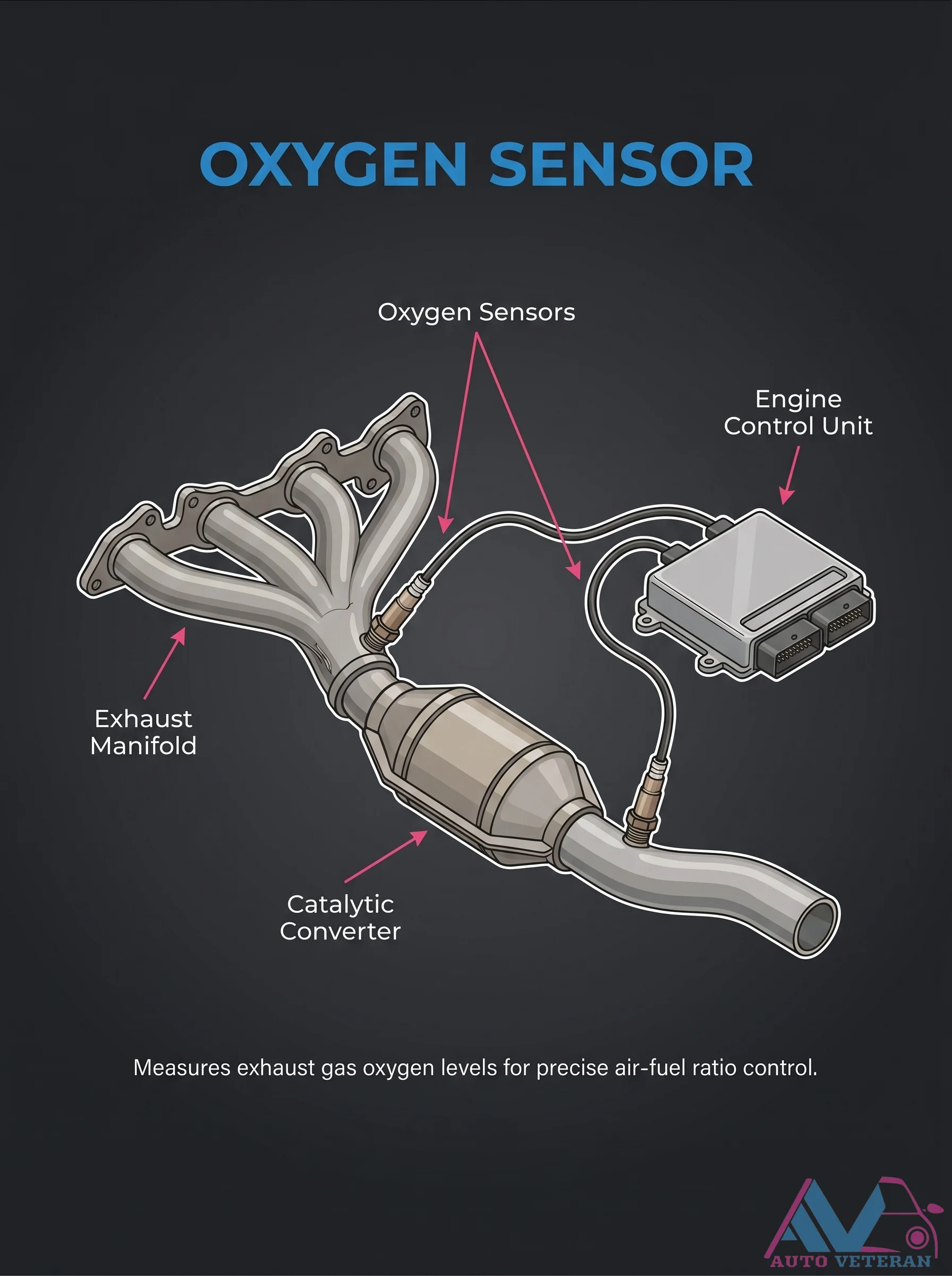
An oxygen sensor mounted in the exhaust stream measures the oxygen content of the exhaust gases, sending a voltage signal to the engine control unit. This feedback loop allows the ECU to adjust the air fuel ratio in real time, optimizing combustion efficiency, reducing emissions, and protecting the catalytic converter from damage.
Oxygen Sensor Air-Fuel Ratio Feedback
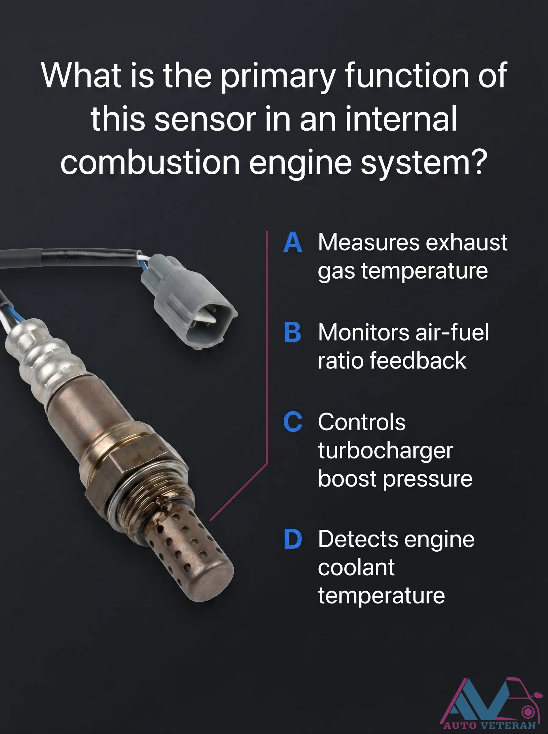
The primary function of the oxygen sensor is to monitor the air-fuel ratio by measuring the oxygen content in the exhaust gases, providing critical feedback to the engine control unit for precise fuel trim adjustments.
Oxygen Sensor Exhaust Monitoring Role
Positioned before and sometimes after the catalytic converter, the oxygen sensor scans exhaust gases for oxygen content and relays that data to the ECM for precise fuel trims, ensuring a balanced air-fuel mixture for peak performance and emissions control.

Oxygen Sensor Failure Symptoms and Service Guidance
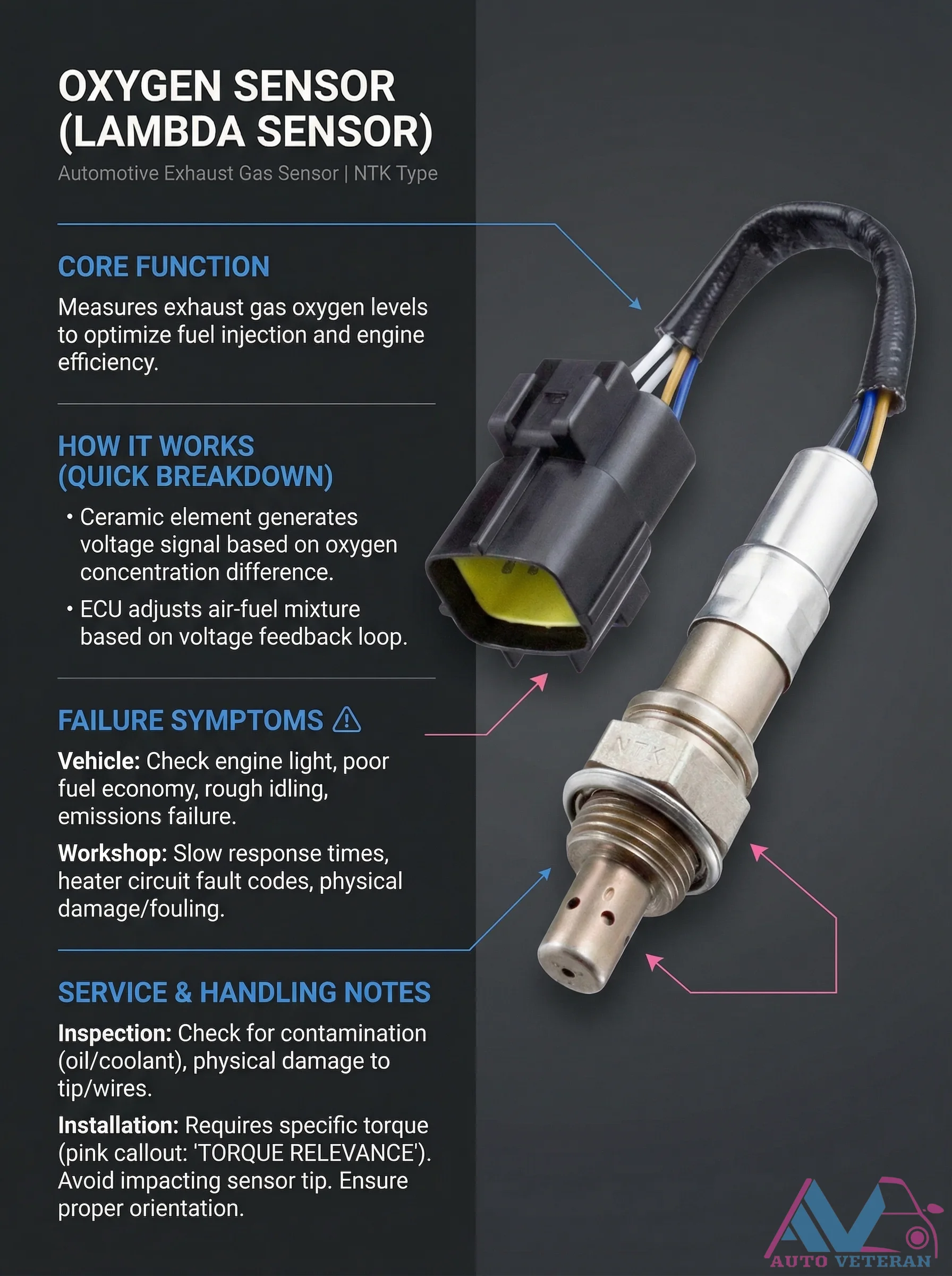
The oxygen sensor, also known as an O2 sensor, plays a critical role in engine management by measuring oxygen levels in exhaust gases to optimize the fuel mixture. Its ceramic element generates voltage based on oxygen differences, sending signals to the Engine Control Unit (ECU) to adjust fuel injection for efficient combustion. When this sensor fails, drivers may experience check engine lights, poor fuel economy, rough idle, or stalling. Technicians might diagnose rich or lean running codes or failed emissions tests. Proper service involves inspecting wiring for damage, ensuring the sensor tip is clean, observing torque specifications during installation, and avoiding grease on threads. Replacement should follow service intervals or symptom onset.
Oxygen Sensor Failure Symptoms and Torque Installation
The NTK type oxygen sensor, also known as a lambda sensor, monitors exhaust gas oxygen levels to optimize fuel injection and engine efficiency. When this critical component fails, drivers experience check engine warnings, reduced fuel economy, rough idling, and emissions test failures. Technicians diagnose slow response times, heater circuit fault codes, and physical damage or fouling. Proper installation requires specific torque settings as noted in technical documentation, careful handling to avoid impact damage to the sensor tip, and correct orientation during mounting. Inspection should include checking for contamination from oil or coolant and examining the tip and wires for physical damage.
Oxygen Sensor Function and Failure Guide
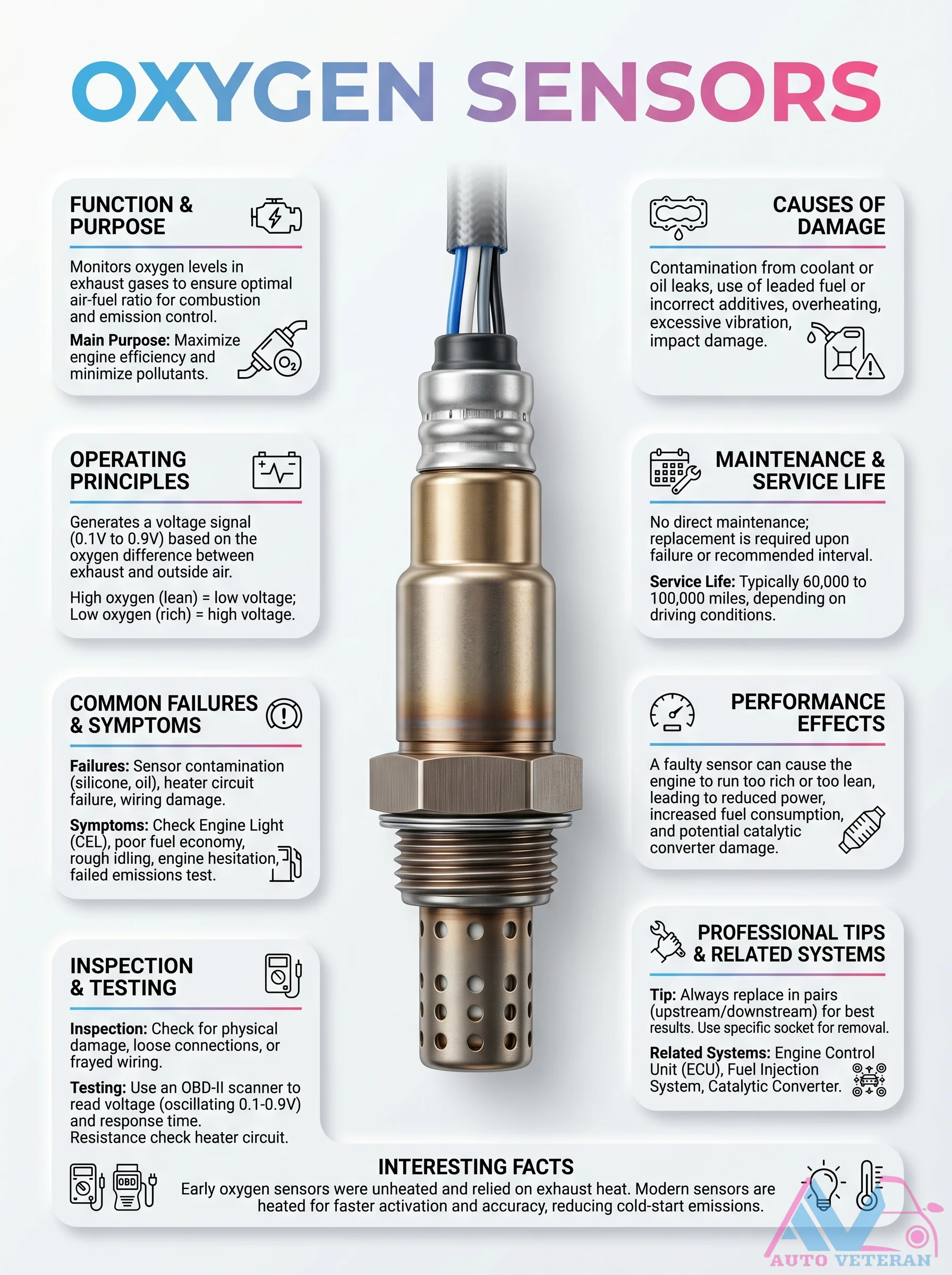
Oxygen sensors monitor oxygen levels in exhaust gases to ensure optimal air-fuel ratio for combustion and emission control. They generate a voltage signal based on oxygen difference between exhaust and outside air; high oxygen (lean) gives low voltage, low oxygen (rich) gives high voltage. Common failures include contamination from coolant or oil leaks, use of leaded fuel, overheating, excessive vibration, and impact damage. Symptoms include Check Engine Light, poor fuel economy, rough idling, engine hesitation, and failed emissions test. Faulty sensors can cause the engine to run too rich or too lean, leading to reduced power, increased fuel consumption, and potential catalytic converter damage. Service life is 60,000 to 100,000 miles depending on driving conditions. No direct maintenance is required; replacement is required upon failure or at recommended intervals. Professional tips include replacing in pairs (upstream/downstream) for best results, using a socket for removal, and testing with an OBD-II scanner to read voltage (oscillating 0.1-0.9V) and response time, as well as resistance check of the heater circuit. Related systems include ECU, fuel injection system, and catalytic converter. Early sensors were unheated and relied on exhaust heat; modern sensors are heated for faster activation and accuracy, reducing cold-start emissions.
Oxygen Sensor Health Check Diagnosis and Testing
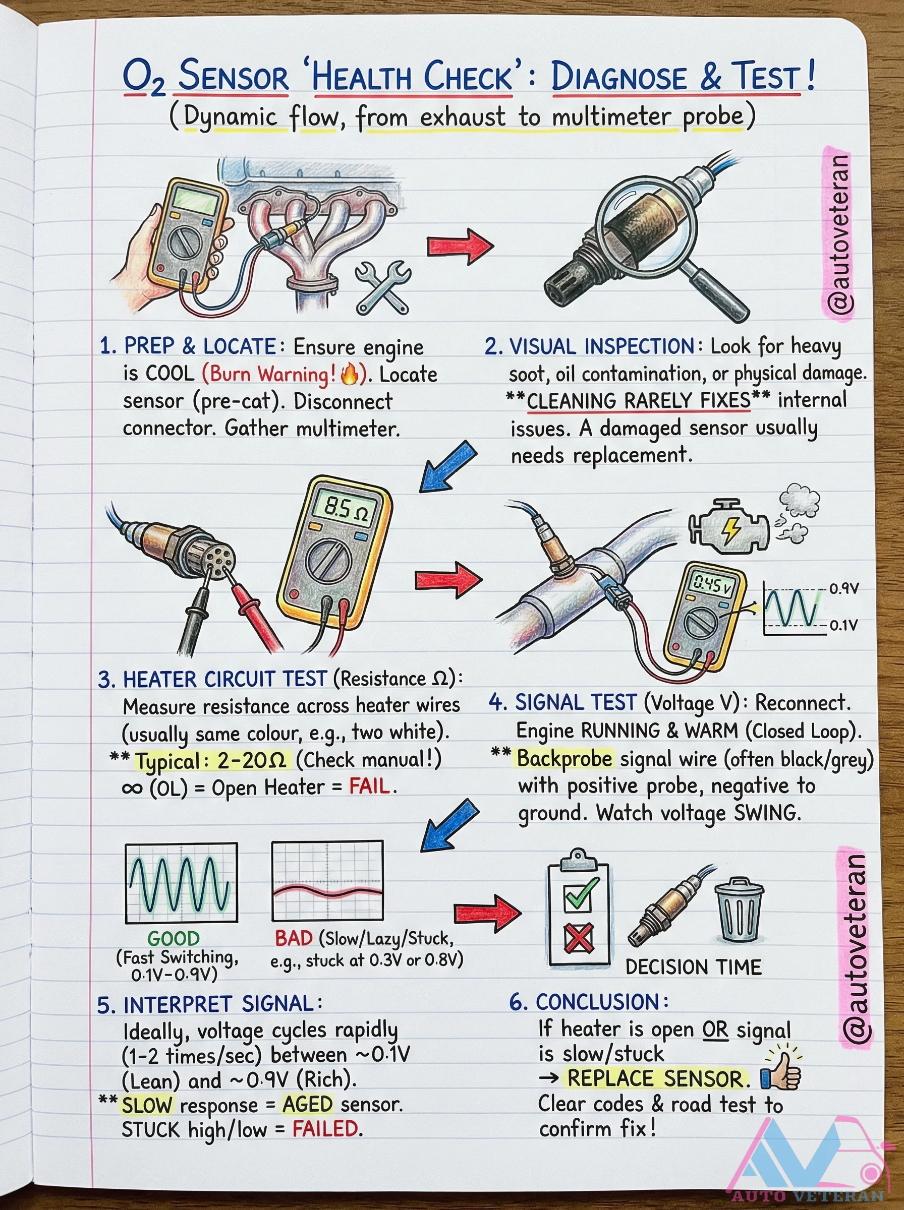
A comprehensive diagnostic procedure for evaluating oxygen sensor health, covering visual inspection for soot and oil contamination, heater circuit resistance testing with typical 2-20 ohm specifications, signal voltage monitoring during closed-loop operation with 0.1V to 0.9V swing expectations, and interpretation of slow response or stuck voltage readings indicating sensor aging or failure.
Oxygen Sensor Narrowband vs Wideband
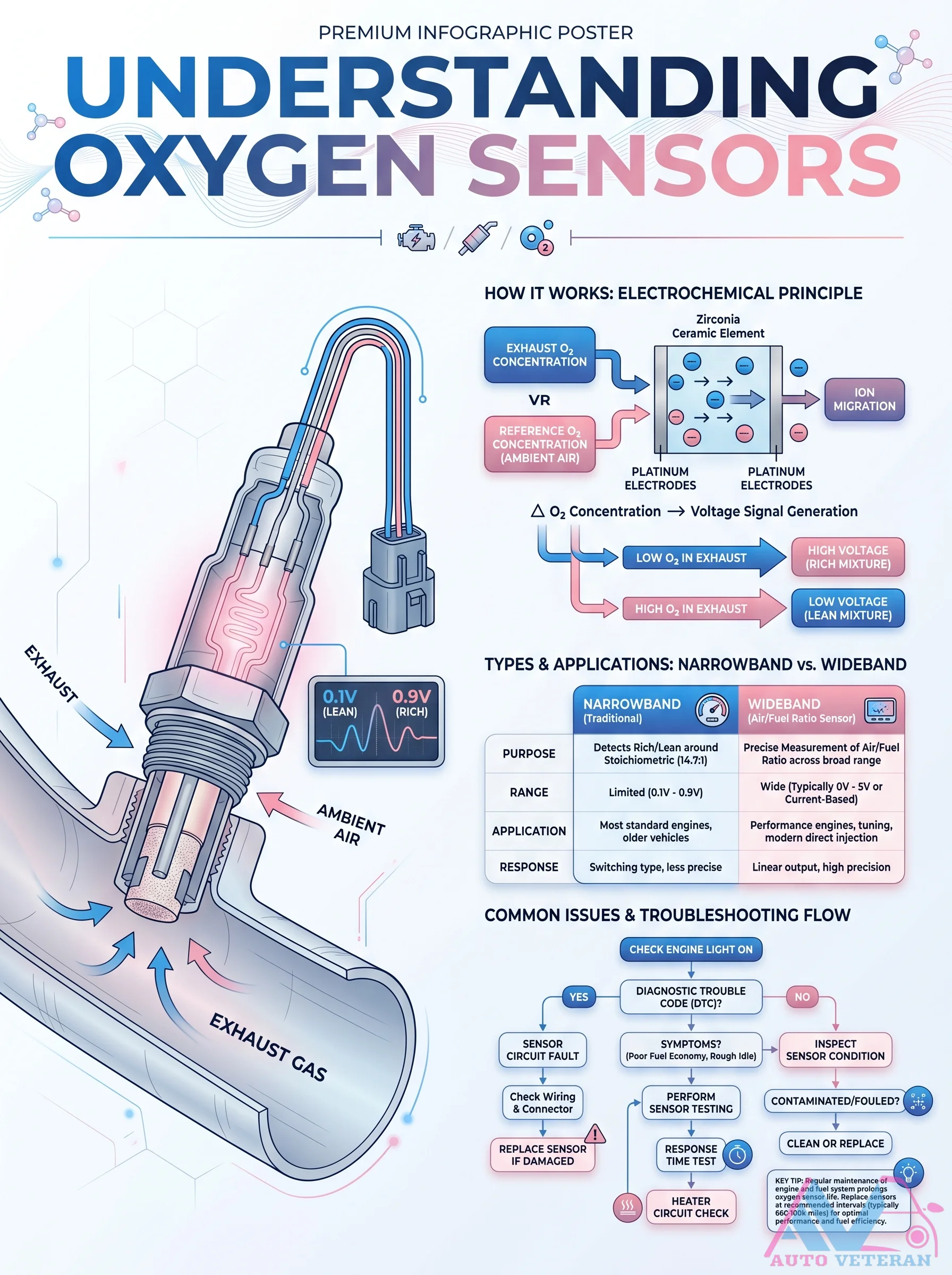
This infographic breaks down the electrochemical principle of zirconia oxygen sensors; comparing narrowband and wideband types. Narrowband sensors produce a voltage swing between 0.1V lean and 0.9V rich, only detecting around stoichiometric. Wideband sensors offer precise Air/Fuel measurement across a broad range using current based output. The troubleshooting flowchart guides you from a check engine light and diagnostic trouble code through inspecting sensor condition, wiring, and connector; testing the heater circuit; and finally cleaning or replacing a contaminated or fouled sensor.