Interactive Explorer
Oxygen Sensor Purpose and Operation
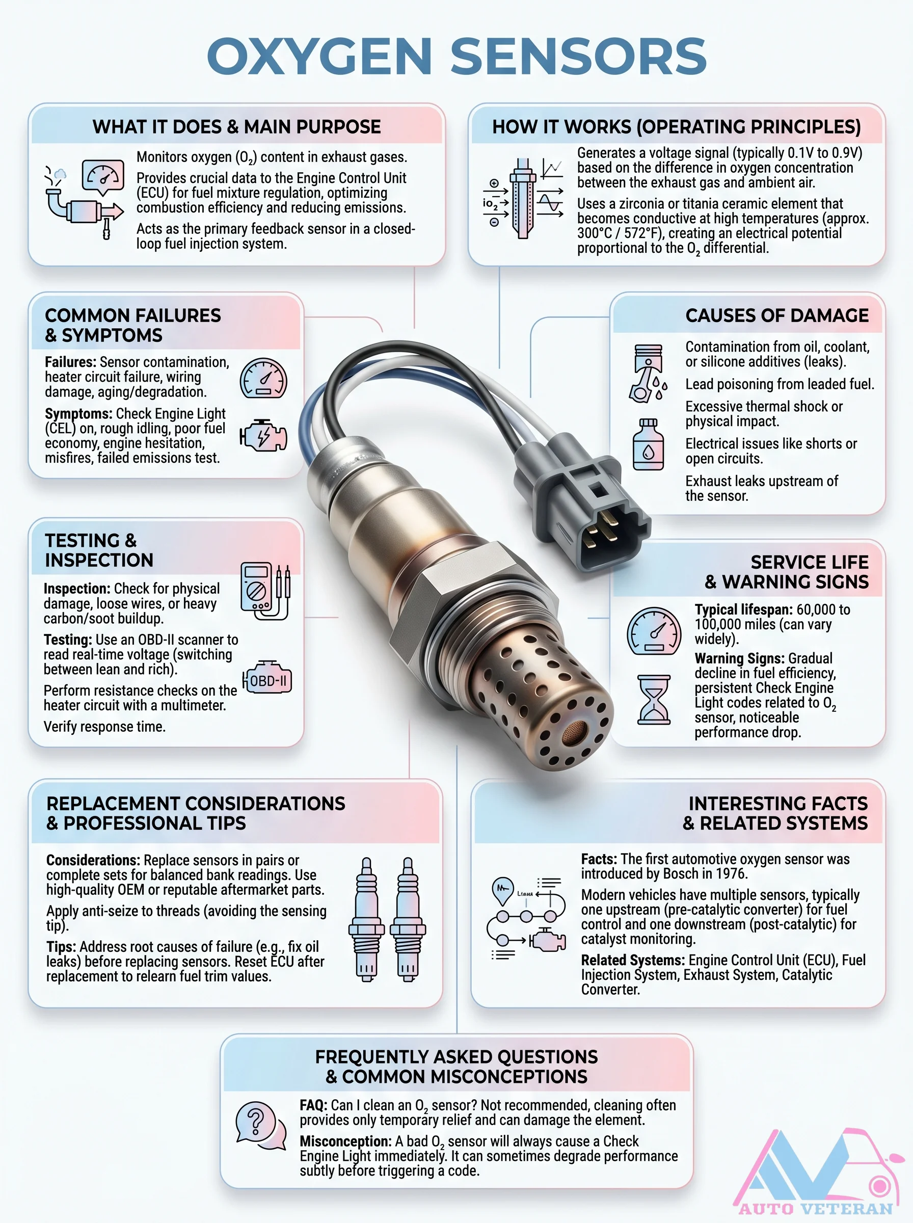
The oxygen sensor monitors exhaust oxygen content and generates a voltage signal between 0.1V and 0.9V based on the difference in oxygen concentration between exhaust gas and ambient air. It uses a zirconia or titania ceramic element that becomes conductive at high temperatures around 300 degrees Celsius or 572 degrees Fahrenheit, creating an electrical potential proportional to the oxygen differential. This provides crucial data to the Engine Control Unit (ECU) for fuel mixture regulation, optimizing combustion efficiency and reducing emissions. It acts as the primary feedback sensor in closed loop fuel injection systems. Common failures include contamination from oil, coolant, or silicone additives; lead poisoning; thermal shock; wiring damage; and aging. Symptoms include Check Engine Light, rough idle, poor fuel economy, engine hesitation, misfires, and failed emissions tests. Testing involves using an OBD II scanner to read real time voltage switching between lean and rich, performing resistance checks on the heater circuit with a multimeter, and verifying response time. Service life is typically 60,000 to 100,000 miles. Replacement considerations include replacing sensors in pairs or complete sets, using high quality OEM or reputable aftermarket parts, applying anti seize to threads while avoiding the sensing element, and resetting the ECU after replacement to relearn fuel trim values. Related systems include the ECU, fuel injection system, exhaust system, and catalytic converter. A common misconception is that a bad oxygen sensor will always cause the Check Engine Light immediately; it can sometimes degrade performance subtly before triggering a code.
Oxygen Sensor System Overview
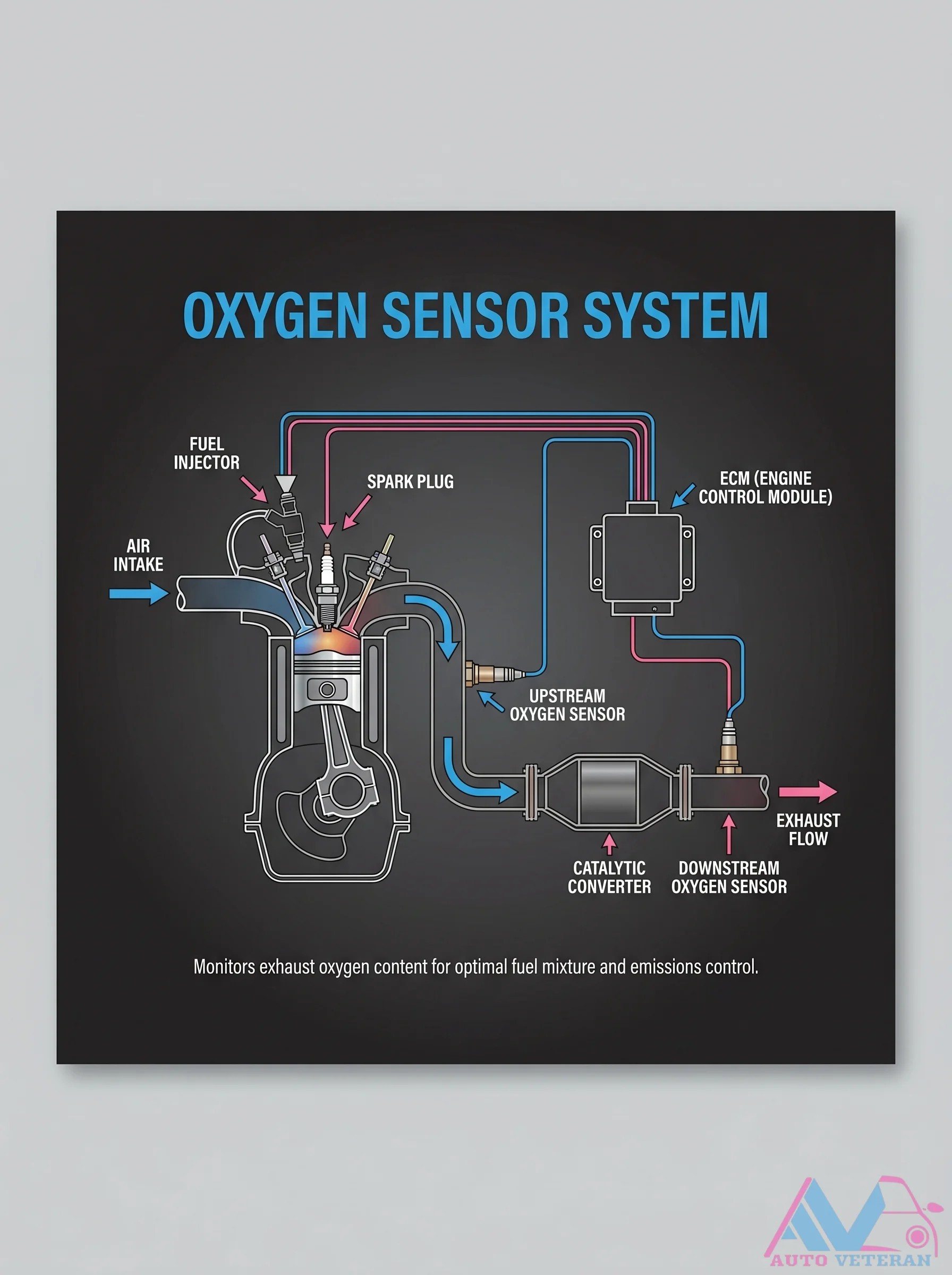
Your vehicle's oxygen sensor system continuously monitors exhaust oxygen content to maintain the optimal air fuel mixture for peak performance and emissions control; the upstream sensor reads raw exhaust before the catalytic converter while the downstream sensor checks converter efficiency; data from these sensors feeds into the Engine Control Module which then adjusts fuel injector pulse width and ignition timing.
Oxygen Sensor System Upstream Downstream Diagram
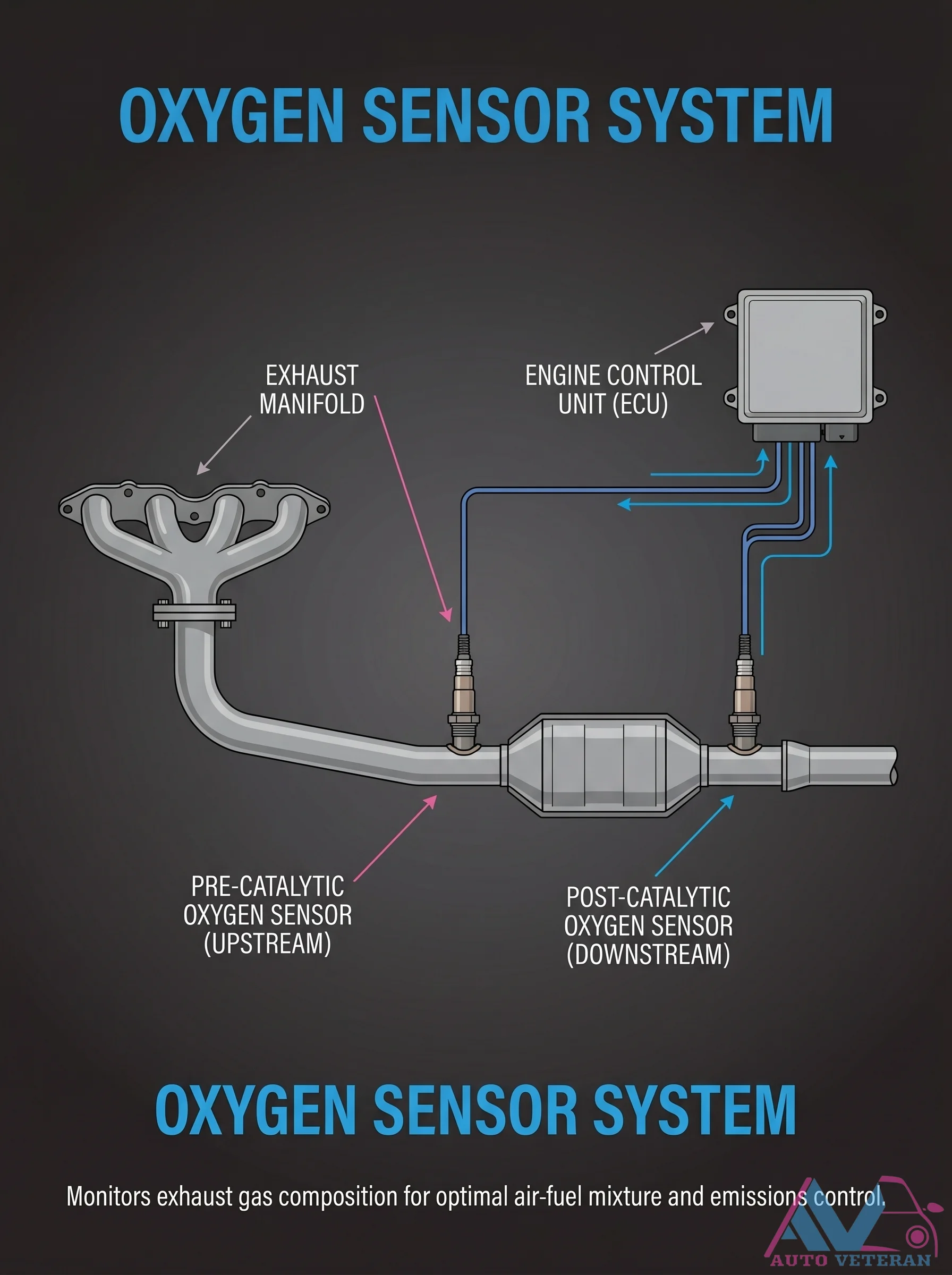
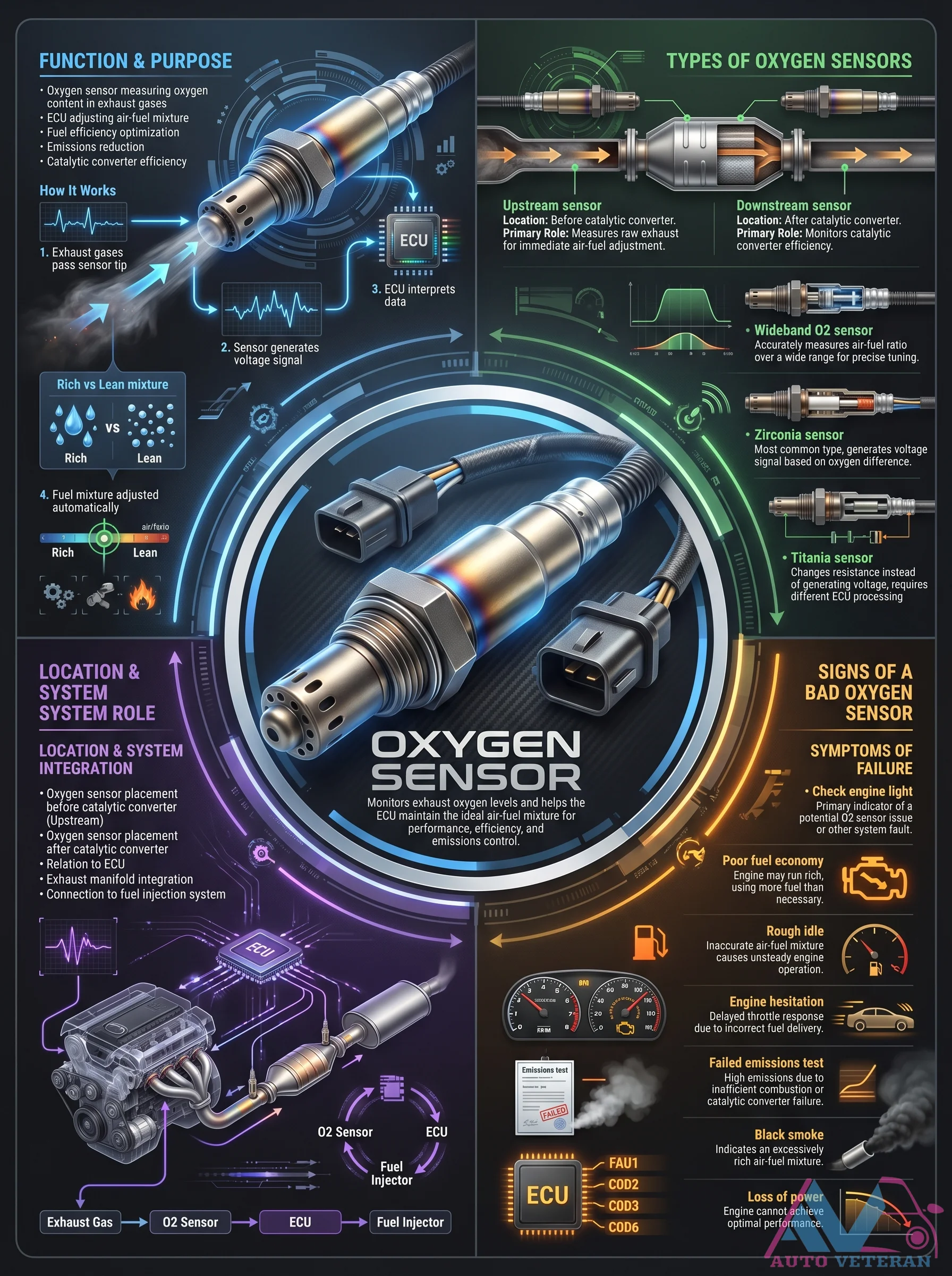
This diagram illustrates the complete oxygen sensor system layout: the upstream pre-catalytic sensor monitors exhaust gas composition before the catalytic converter, while the downstream post-catalytic sensor checks converter efficiency. Both sensors work with the Engine Control Unit ECU to constantly adjust the air fuel mixture for optimal combustion, fuel economy, and emissions control according to AUTO VETERAN principles.
Oxygen Sensor Testing and Replacement Procedure
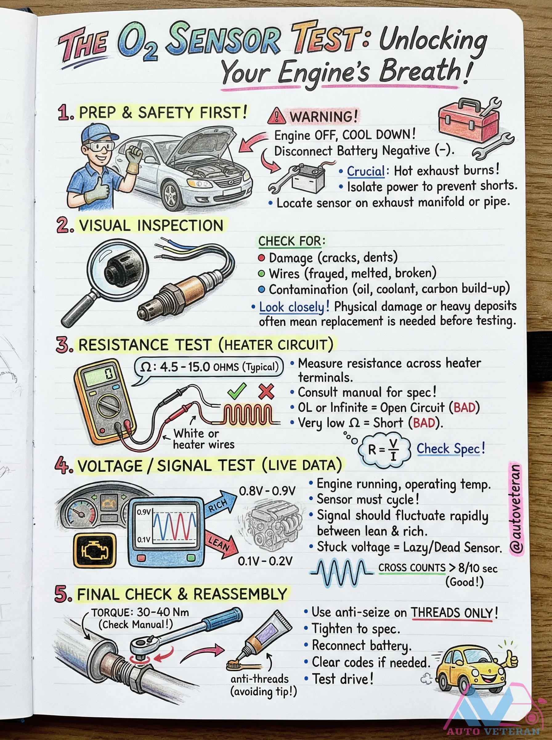
This comprehensive guide details the essential steps for properly testing and replacing an oxygen sensor, including critical safety precautions, visual inspection criteria, heater circuit resistance testing with typical 4.5-15.0 ohm specifications, live data voltage signal analysis showing proper 0.8V-0.9V fluctuation patterns, and proper installation techniques with 30-40 Nm torque specifications and anti-seize application guidelines.
Oxygen Sensor Types and Function Guide
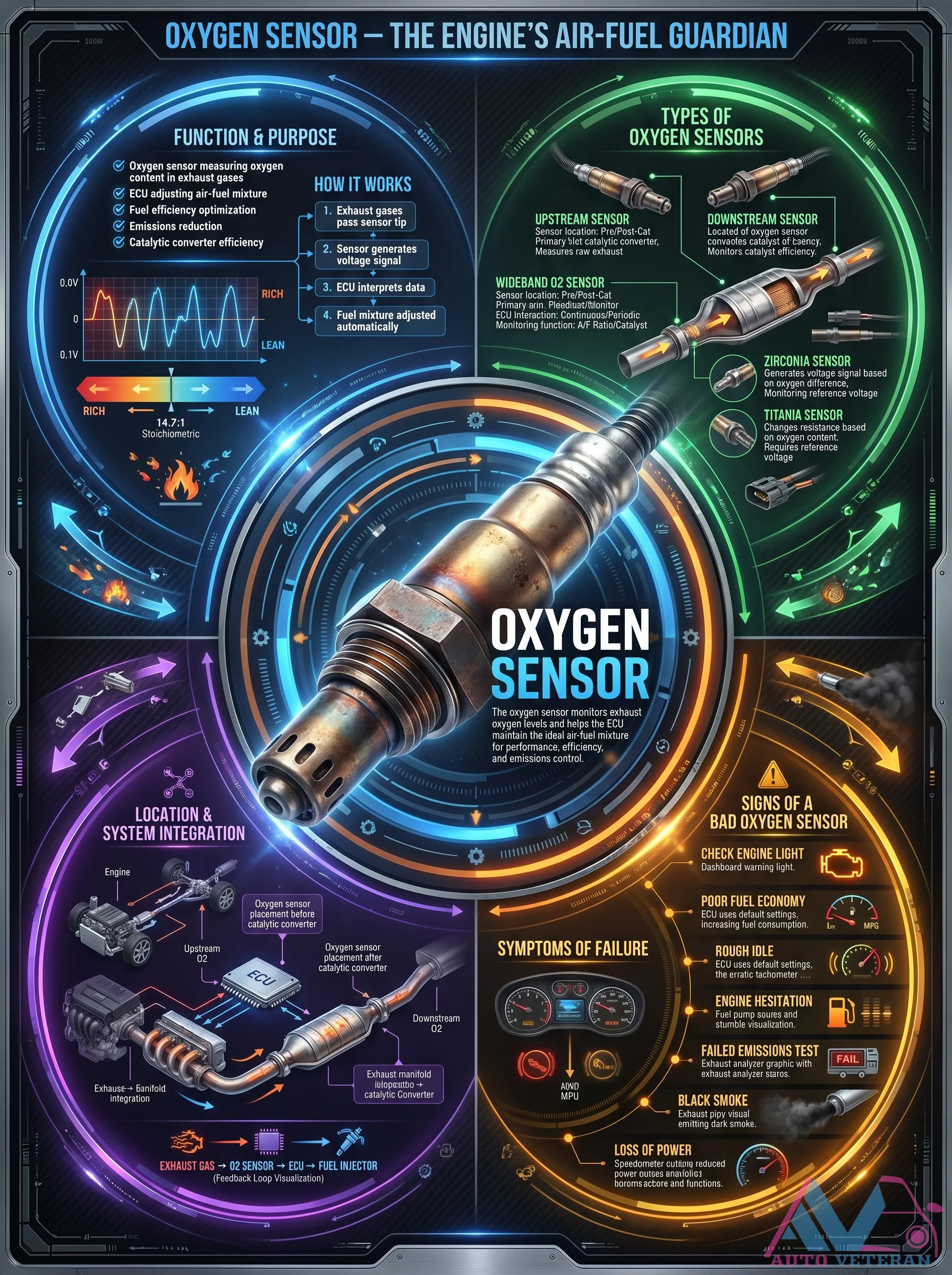
The oxygen sensor acts as the engine's air-fuel guardian, constantly monitoring exhaust oxygen levels to help the ECU adjust the mixture for optimal combustion. This poster covers sensor types like zirconia and titania, upstream versus downstream locations, and symptoms of failure such as poor fuel economy, rough idle, engine hesitation, and black smoke. Understanding these details is key to diagnosing and replacing a faulty O2 sensor to restore performance and pass emissions tests.
Oxygen Sensor Types and Functions
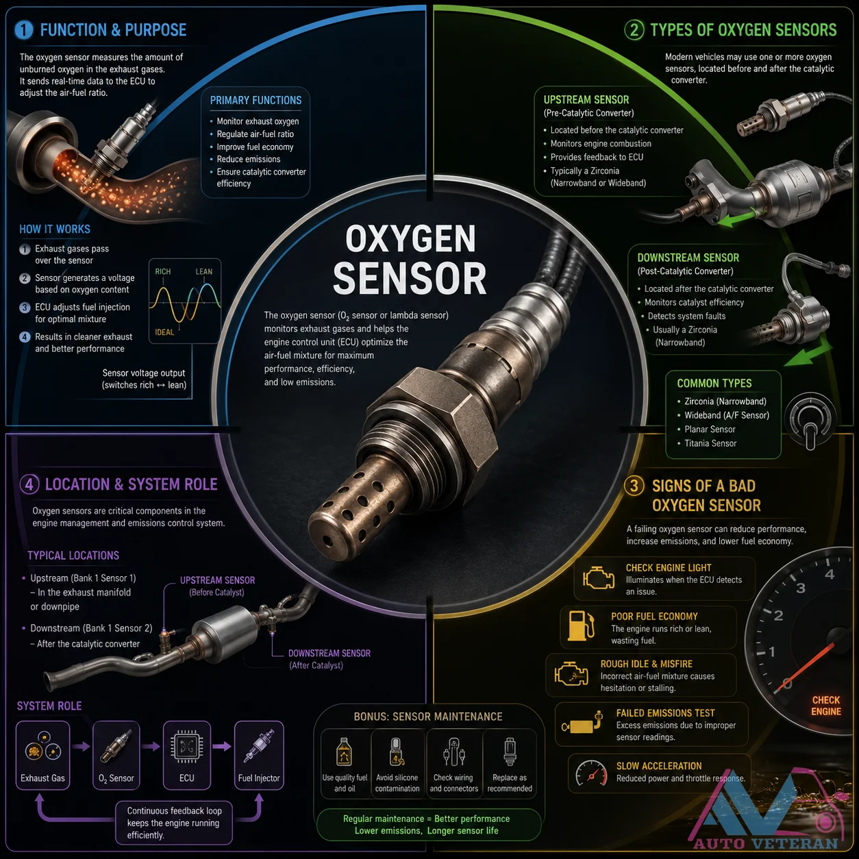
Modern vehicles often use multiple oxygen sensors located before and after the catalytic converter. The upstream sensor monitors exhaust oxygen to regulate the air fuel ratio, while the downstream sensor checks catalyst efficiency. Common types include zirconia narrowband, wideband A/F sensor, planar sensor, and titania sensor. A failing oxygen sensor triggers the check engine light, causes poor fuel economy, rough idle, misfire, failed emissions tests, and slow acceleration. Use quality fuel, avoid silicone contamination, check wiring and connectors, and replace at recommended intervals.
Oxygen Sensor Types Location and Failure Symptoms
This guide covers everything about oxygen sensors: their function measuring exhaust oxygen levels for ECU fuel trim adjustments, upstream versus downstream locations before and after the catalytic converter, types including zirconia and titania sensors that generate voltage or change resistance, and common failure symptoms like check engine light, poor fuel economy, rough idle, engine hesitation, black smoke from rich mixture, and failed emissions tests due to inefficient combustion or catalytic converter damage.